EP0910248B1 - Method, device and cutting tool for producing individual pieces of dough from a continuous line of dough - Google Patents
Method, device and cutting tool for producing individual pieces of dough from a continuous line of dough Download PDFInfo
- Publication number
- EP0910248B1 EP0910248B1 EP98912488A EP98912488A EP0910248B1 EP 0910248 B1 EP0910248 B1 EP 0910248B1 EP 98912488 A EP98912488 A EP 98912488A EP 98912488 A EP98912488 A EP 98912488A EP 0910248 B1 EP0910248 B1 EP 0910248B1
- Authority
- EP
- European Patent Office
- Prior art keywords
- dough
- cutting
- punch tool
- punch
- strip
- Prior art date
- Legal status (The legal status is an assumption and is not a legal conclusion. Google has not performed a legal analysis and makes no representation as to the accuracy of the status listed.)
- Expired - Lifetime
Links
- 238000005520 cutting process Methods 0.000 title claims description 140
- 238000000034 method Methods 0.000 title claims description 43
- 238000004080 punching Methods 0.000 claims description 88
- 230000033001 locomotion Effects 0.000 claims description 39
- 238000000151 deposition Methods 0.000 claims description 8
- 238000006073 displacement reaction Methods 0.000 claims description 8
- 238000004519 manufacturing process Methods 0.000 claims description 7
- 238000012545 processing Methods 0.000 claims description 7
- 230000001360 synchronised effect Effects 0.000 claims description 3
- 230000008878 coupling Effects 0.000 claims 1
- 238000010168 coupling process Methods 0.000 claims 1
- 238000005859 coupling reaction Methods 0.000 claims 1
- 239000000758 substrate Substances 0.000 claims 1
- 239000002699 waste material Substances 0.000 claims 1
- 230000008569 process Effects 0.000 description 12
- 238000003860 storage Methods 0.000 description 11
- 229920001971 elastomer Polymers 0.000 description 9
- 235000012830 plain croissants Nutrition 0.000 description 7
- 239000000806 elastomer Substances 0.000 description 6
- 239000002131 composite material Substances 0.000 description 4
- 239000004033 plastic Substances 0.000 description 4
- 229920003023 plastic Polymers 0.000 description 4
- 238000003892 spreading Methods 0.000 description 4
- 230000007480 spreading Effects 0.000 description 4
- 230000008901 benefit Effects 0.000 description 3
- 239000003292 glue Substances 0.000 description 3
- 238000012549 training Methods 0.000 description 3
- 238000004804 winding Methods 0.000 description 3
- 230000008859 change Effects 0.000 description 2
- 239000003795 chemical substances by application Substances 0.000 description 2
- 230000000295 complement effect Effects 0.000 description 2
- 238000013016 damping Methods 0.000 description 2
- 230000001960 triggered effect Effects 0.000 description 2
- 235000007688 Lycopersicon esculentum Nutrition 0.000 description 1
- 240000003768 Solanum lycopersicum Species 0.000 description 1
- 208000012886 Vertigo Diseases 0.000 description 1
- 230000009471 action Effects 0.000 description 1
- 235000015173 baked goods and baking mixes Nutrition 0.000 description 1
- 230000005540 biological transmission Effects 0.000 description 1
- 210000000078 claw Anatomy 0.000 description 1
- 238000004891 communication Methods 0.000 description 1
- 238000010276 construction Methods 0.000 description 1
- 239000002173 cutting fluid Substances 0.000 description 1
- 238000013461 design Methods 0.000 description 1
- 238000009826 distribution Methods 0.000 description 1
- 238000005516 engineering process Methods 0.000 description 1
- 230000000977 initiatory effect Effects 0.000 description 1
- 238000003780 insertion Methods 0.000 description 1
- 230000037431 insertion Effects 0.000 description 1
- 230000000149 penetrating effect Effects 0.000 description 1
- 230000035515 penetration Effects 0.000 description 1
- 230000010363 phase shift Effects 0.000 description 1
- 229920002635 polyurethane Polymers 0.000 description 1
- 239000004814 polyurethane Substances 0.000 description 1
- 230000009467 reduction Effects 0.000 description 1
- 230000001105 regulatory effect Effects 0.000 description 1
- 238000000926 separation method Methods 0.000 description 1
- 230000006641 stabilisation Effects 0.000 description 1
- 238000011105 stabilization Methods 0.000 description 1
Images
Classifications
-
- A—HUMAN NECESSITIES
- A21—BAKING; EDIBLE DOUGHS
- A21C—MACHINES OR EQUIPMENT FOR MAKING OR PROCESSING DOUGHS; HANDLING BAKED ARTICLES MADE FROM DOUGH
- A21C3/00—Machines or apparatus for shaping batches of dough before subdivision
- A21C3/06—Machines for coiling sheets of dough, e.g. for producing rolls
-
- A—HUMAN NECESSITIES
- A21—BAKING; EDIBLE DOUGHS
- A21C—MACHINES OR EQUIPMENT FOR MAKING OR PROCESSING DOUGHS; HANDLING BAKED ARTICLES MADE FROM DOUGH
- A21C11/00—Other machines for forming the dough into its final shape before cooking or baking
- A21C11/10—Other machines for forming the dough into its final shape before cooking or baking combined with cutting apparatus
-
- A—HUMAN NECESSITIES
- A21—BAKING; EDIBLE DOUGHS
- A21C—MACHINES OR EQUIPMENT FOR MAKING OR PROCESSING DOUGHS; HANDLING BAKED ARTICLES MADE FROM DOUGH
- A21C9/00—Other apparatus for handling dough or dough pieces
- A21C9/08—Depositing, arranging and conveying apparatus for handling pieces, e.g. sheets of dough
- A21C9/085—Separating, spacing, orienting or aligning discrete dough pieces, e.g. after passing a cutting device
-
- Y—GENERAL TAGGING OF NEW TECHNOLOGICAL DEVELOPMENTS; GENERAL TAGGING OF CROSS-SECTIONAL TECHNOLOGIES SPANNING OVER SEVERAL SECTIONS OF THE IPC; TECHNICAL SUBJECTS COVERED BY FORMER USPC CROSS-REFERENCE ART COLLECTIONS [XRACs] AND DIGESTS
- Y10—TECHNICAL SUBJECTS COVERED BY FORMER USPC
- Y10S—TECHNICAL SUBJECTS COVERED BY FORMER USPC CROSS-REFERENCE ART COLLECTIONS [XRACs] AND DIGESTS
- Y10S83/00—Cutting
- Y10S83/929—Particular nature of work or product
- Y10S83/932—Edible
-
- Y—GENERAL TAGGING OF NEW TECHNOLOGICAL DEVELOPMENTS; GENERAL TAGGING OF CROSS-SECTIONAL TECHNOLOGIES SPANNING OVER SEVERAL SECTIONS OF THE IPC; TECHNICAL SUBJECTS COVERED BY FORMER USPC CROSS-REFERENCE ART COLLECTIONS [XRACs] AND DIGESTS
- Y10—TECHNICAL SUBJECTS COVERED BY FORMER USPC
- Y10T—TECHNICAL SUBJECTS COVERED BY FORMER US CLASSIFICATION
- Y10T83/00—Cutting
- Y10T83/04—Processes
- Y10T83/0448—With subsequent handling [i.e., of product]
-
- Y—GENERAL TAGGING OF NEW TECHNOLOGICAL DEVELOPMENTS; GENERAL TAGGING OF CROSS-SECTIONAL TECHNOLOGIES SPANNING OVER SEVERAL SECTIONS OF THE IPC; TECHNICAL SUBJECTS COVERED BY FORMER USPC CROSS-REFERENCE ART COLLECTIONS [XRACs] AND DIGESTS
- Y10—TECHNICAL SUBJECTS COVERED BY FORMER USPC
- Y10T—TECHNICAL SUBJECTS COVERED BY FORMER US CLASSIFICATION
- Y10T83/00—Cutting
- Y10T83/04—Processes
- Y10T83/0505—With reorientation of work between cuts
- Y10T83/051—Relative to same tool
-
- Y—GENERAL TAGGING OF NEW TECHNOLOGICAL DEVELOPMENTS; GENERAL TAGGING OF CROSS-SECTIONAL TECHNOLOGIES SPANNING OVER SEVERAL SECTIONS OF THE IPC; TECHNICAL SUBJECTS COVERED BY FORMER USPC CROSS-REFERENCE ART COLLECTIONS [XRACs] AND DIGESTS
- Y10—TECHNICAL SUBJECTS COVERED BY FORMER USPC
- Y10T—TECHNICAL SUBJECTS COVERED BY FORMER US CLASSIFICATION
- Y10T83/00—Cutting
- Y10T83/162—With control means responsive to replaceable or selectable information program
-
- Y—GENERAL TAGGING OF NEW TECHNOLOGICAL DEVELOPMENTS; GENERAL TAGGING OF CROSS-SECTIONAL TECHNOLOGIES SPANNING OVER SEVERAL SECTIONS OF THE IPC; TECHNICAL SUBJECTS COVERED BY FORMER USPC CROSS-REFERENCE ART COLLECTIONS [XRACs] AND DIGESTS
- Y10—TECHNICAL SUBJECTS COVERED BY FORMER USPC
- Y10T—TECHNICAL SUBJECTS COVERED BY FORMER US CLASSIFICATION
- Y10T83/00—Cutting
- Y10T83/202—With product handling means
- Y10T83/2074—Including means to divert one portion of product from another
-
- Y—GENERAL TAGGING OF NEW TECHNOLOGICAL DEVELOPMENTS; GENERAL TAGGING OF CROSS-SECTIONAL TECHNOLOGIES SPANNING OVER SEVERAL SECTIONS OF THE IPC; TECHNICAL SUBJECTS COVERED BY FORMER USPC CROSS-REFERENCE ART COLLECTIONS [XRACs] AND DIGESTS
- Y10—TECHNICAL SUBJECTS COVERED BY FORMER USPC
- Y10T—TECHNICAL SUBJECTS COVERED BY FORMER US CLASSIFICATION
- Y10T83/00—Cutting
- Y10T83/202—With product handling means
- Y10T83/2092—Means to move, guide, or permit free fall or flight of product
- Y10T83/2192—Endless conveyor
- Y10T83/2194—And means to remove product therefrom
-
- Y—GENERAL TAGGING OF NEW TECHNOLOGICAL DEVELOPMENTS; GENERAL TAGGING OF CROSS-SECTIONAL TECHNOLOGIES SPANNING OVER SEVERAL SECTIONS OF THE IPC; TECHNICAL SUBJECTS COVERED BY FORMER USPC CROSS-REFERENCE ART COLLECTIONS [XRACs] AND DIGESTS
- Y10—TECHNICAL SUBJECTS COVERED BY FORMER USPC
- Y10T—TECHNICAL SUBJECTS COVERED BY FORMER US CLASSIFICATION
- Y10T83/00—Cutting
- Y10T83/444—Tool engages work during dwell of intermittent workfeed
- Y10T83/4475—Tool has motion additional to cutting stroke during tool cycle
- Y10T83/4483—Tool has work-feeding motion
Definitions
- the invention relates to a method for producing individual pieces of dough a continuous dough sheet by inserting a into the end section of the dough sheet row of separate, each oblique or transverse to the longitudinal direction of the web is cut out in self-contained contours, which the dough pieces correspond, these contours or dough pieces lying side by side in a row removed from the end of the web and rotated or pivoted for further processing or stored in any other way, according to the preamble of claim 1.
- the invention relates to a device for separating dough pieces from a continuous dough sheet, suitable for carrying out the above method and with the following Components is provided: with a and the of punched or other actuated and / or moved by drive means Cutting tool, with a table opposite this as a top, bottom or storage for the dough band and the resulting from it by means of the punching or cutting tool cut pieces of dough and with acting on the drive means Control means for coordinating the device components to be moved or driven including the punching or cutting tool.
- Such methods and devices are used to cut dough for certain baked goods that are wound from pieces of dough, in particular Croissants.
- isosceles triangles are always made from the dough sheet cut out so that no dough remains (see for example EP 0 382 105 A1).
- windingsers are known Machines that cut triangles out of the dough sheet and one behind the other arranged conveyor belts over differential speeds the cut Pull the triangles apart. These are then added to other associations Conveyor belts pass at right angles to the previous conveyor belts are arranged. In this way, expensive spreading and Rotation devices for the dough pieces are spared.
- the disadvantage is that the direction of transport must be deflected by 90 ° (for example, if directly on one Freezer should be worked).
- Another disadvantage is that because of the location the base leg of the cut triangle left and right of the machine one angle device is required. When using only one winder, the to cut out the dough piece, each with a dough piece bandage a dry top and a dough bandage with a wet top enters the winder.
- EP-A-0 482 917 discloses a method and an apparatus for separating and Aligning croissant dough pieces.
- the use of Gripping claws 51 with projecting pins penetrating into the dough (see FIG. 2) suggested. These pin grippers are used at both Separating device 5 as well as the alignment device 6 (see FIG. 2) used. Penetration of pins 62 into the dough piece to align it is clearly shown in Figure 4. Above all, it can be seen from this that the pin grippers 51 or 62 work without cutting action.
- the pin grippers 51 and 62 are unique intended to have already cut dough pieces in the further course without Cut apart to move and align. So the singling out and aligning the already cut pieces of dough with specially designed ones Grippers with protruding pins that penetrate the dough pieces accomplished.
- the invention has for its object, while avoiding the above Disadvantages for the transport of dough in line, a method and an apparatus for Cutting dough pieces out of continuous dough bands as well as for aligning them Place the cut dough pieces for further processing to create a small number of functional or structural components and a low manufacturing and design effort, especially what the Dough piece guidance is concerned, it is also necessary to glue the dough pieces with each other immediately after being cut up.
- the one or more punching agents be it a combination of Cutting contours as part of a punching tool, not just for Cutting out the dough pieces, but also for transport, for moving and used to move the cut dough pieces. Expensive spreading and Turning devices with automatic gripper systems can be saved. If according to the invention one or more Stamping tools each used with a preferably elongated upper part be the one or more cutting sections generating the contours for Generation of the dough piece row has, this association of dough pieces hold, guide and between the cutting elements of the upper part of the punching tool move.
- An elongated shape for the upper part is useful because then several cutting sections each lined up with a dough piece contour leave, even one after the other in the transport direction. For this it is advantageous that immediately after cutting or punching the dough piece contours into the Dough band end the pressure on the punch top against the associated one Lower part is withdrawn so far that the upper part with its cutting edges slide on the surface of the lower part and / or be moved over it can. This allows the cut-out dough piece bandage or one only piece of dough with a single cutting means particularly easily from the end of the dough sheet Remove, rotate or otherwise position over a surface or side.
- the dough piece contour is in the follow-up cutting process manufactured: one in front of the movable punching tools installed, stationary punching device cuts, for example the base of an isosceles triangular dough contour, while the Cut the leg with the cutting means used to move the dough piece become.
- follow-up cutting tools it makes sense to add the dough piece to grasp with Pickem, since the contour of the punching tool is not closed is.
- the punching tool not be turned to move the dough pieces. For example with rectangular, square or round products where turning doesn't make sense linear movement would suffice.
- the throughput of cut and aligned dough pieces can be increased if after one embodiment of the method according to the invention, as many punching agents as possible, each with a cutting contour for the shape of the dough in the transport direction next to each other and / or one behind the other in the end of the dough band arranged and in association with each other or also isolated from each other synchronized and / or coordinated operated and moved.
- This Thought can be through the above-mentioned elongated shape for the Punching tool upper part, in which several cutting means are lined up in one piece can be implement in practice.
- the above-mentioned object of the invention can be done with the above Procedure after additional training solve the process invention explained so far that the Pieces of dough after being cut out in their arrangement and / or in their bandage or their series are left, and by means of the cutting means or this row or arrangement of dough pieces as a whole is removed from the end of the web and is rotated and then deposited, after which the cutting means in their cut-out position be moved back to the (end) web end and rotated again.
- This is also the aim mentioned in the generic method Goal to create a piece of dough in line, especially in croissant production, for the isosceles triangles the triangle base side can be cut out as in the transport direction Position the pointing face.
- the base side is opposite Triangle tip turned backwards against the direction of dough transport.
- the dough pieces can have any desired shape. In practice, however, mostly take place in connection with croissant production the contours of an isosceles triangle or a trapezoid Application which are symmetrical with respect to a central axis. Because of the As is known per se, demands for the remaining dough being free (cf. EP 0 382 105 A1), the dough pieces in the shape of an isosceles triangle or a symmetrical trapezoid at the end of the dough sheet so that the end of the dough sheet runs approximately sawtooth-like. In this context an embodiment of the method according to the invention is expedient, after which each dough cutting process or the cutting means, if necessary Can be rotated 180 ° in an alternating direction. Thereby it is possible that the cutting contours of the cutting tool with cover the resulting sawtooth-shaped dough sheet end edge, the after each cutting process according to a 180 ° phase shift or a mirror image is newly created.
- the punching to provide tool-capturing guide means that are so connected to the drive and / or control means are coupled and run parallel to the table top, that the punch with the cut dough pieces can slide directly on and / or along the top of the table and from the end of the dough sheet is removable and rotatable or pivotable. These movements run in a plane parallel to the top of the table and across or at an angle to the cutting direction.
- the punching tools not only for the actual purpose of cutting out Pieces of dough, also used to transport and align them. This saves the arrangement of separate, additional functional components like grabs.
- the freshly cut dough pieces can be timely move away from the end of the dough sheet before they stick together.
- the invention Device provided that the drive means one to the dough sheet directed pressure or actuating device and one of these opposed or have counteracting reset device, with each the cutting elements of the punch are connected. there is the return path triggered by the reset device for the cutting elements dimensioned so that the cutting elements except positive engagement with the Top of the table, but the punch with the cut Pieces of dough in frictional engagement and / or sliding contact with the Top of the table remains. This ensures that the dough pieces are always between the punching tool and the table top (which at the Punching forms the lower punch part) held, guided and moved can.
- the structure of the guide means for the punching tool is that this one from the end of the dough in or parallel to the direction of transport to the storage place of the dough pieces running linear guide in which a Punching tool-carrying slide can be moved back and forth is.
- a rotary bearing is formed in or on the slide, on which the punching tool is rotatably attached.
- the drive means are corresponding with a linear drive module for moving the carriage and one Rotary drive module for rotating the punch for alignment of the pieces of dough to be put down, these modules for their coordination and / or synchronization with each other and / or with any pieces of dough or dough sheet conveying means are coupled to the control means.
- the rotary drive module is an advantage for saving drive components passively formed, such that it is driven by the linear drive or Carriage over driver elements around the axis of rotation of the rotary bearing in Rotation is offset.
- the rotary drive - how for the Unearantrieb - separate drive units, for example an electric one To provide a rotary motor.
- an electric linear actuator would be used Linear motor expedient, because then both electric motors have a common one Communication system directed and / or regulated by the control means could become.
- the solution of the above inventive task is also used with the
- the device according to the invention can be combined with a punching tool characterized by a first and a second holding plate as the basic structure, the are connected to one another in the punching stroke direction so as to be (re) adjustable.
- the first Holding plate carries the cutting elements with the dough piece contour or generating cutting edges
- the second holding plate is provided with elements for Ejecting and / or holding down dough on or between the cutting elements Mistake.
- the dough ejection and / or holding elements are immediate in addition to the cutting elements and / or slidable with an adjustment stroke arranged, which extends on both sides of the cutting edge of the cutting element.
- the frame 1 of the machine according to the invention is for combined punching and positioning of dough pieces on a frame 3 supported on the ground or in a machine foundation.
- a linear guide 5 with a guide rod 7 installed, which extends parallel to the dough transport direction or to the machine side.
- a carriage 11 in or against the dough transport direction 9 slidably mounted; in the practical embodiment two guide rods 7 pass through the slide 11 via trained therein through guide bores 13.
- rodless pneumatic cylinder 15 arranged above the carriage 11 and supported against the mesh frame 1. Whose movement stroke extends parallel to the guide rod 7 of the slide linear guide 5.
- the pneumatic cylinder 15 is timely controlled or actuated to drive pin 17, both on Pneumatic cylinder 15 and on the carriage 11 to their guides extending transversely are attached, the carriage 11 in and against the dough transport direction 9 to move.
- the linear guide system can also be reversed Three-phase drive are formed, which drives the carriage through a toothed belt.
- the slide guide can be used, for example, as a linear guide be executed.
- 1 and 2 are a further pneumatic cylinder in the carriage 11 on the top 19 for impressing the punch stroke for a punch tool 21 and the underside of a tool carrier 23 for carrying and holding the punch 21 attached.
- At the upper, front end of the punch stroke pneumatic cylinder 19 is on a continuous central rod 25 at the top
- a damping disc 27 placed (according to Fig. 1, a rubber damping spring 113). This can be combined with one from above front protruding external thread 29 of the central rod 25 screwed Adjusting nut 31 as a counter bearing for adjusting the distance 32 of the cutting elements Use the punch 21 to the lower punch 33.
- the Stamping tool 21 can at the lower end of the tool carrier 23 via a (shown schematically) quick change device 35 may be attached.
- this is by two arranged symmetrically to the pivot point of the turntable 39 Guide recesses 41 realized in the given time (see below) the piston rods 43 of two in the machine room 1 opposite arranged pneumatic cylinders 45 to one of the (not shown) Control means to be threaded at a specific time.
- This will the turntable 39, when it is moved linearly by the carriage 11, simultaneously set in rotation about its axis of rotation, which also applies to the punching tool 21 is transmitted.
- FIG. 2 are at the rear and front dead center of the movement stroke of the Carriage 11 or on the corresponding rear and front sides of the machine frame 1 centering forks 47a, 47b attached to the respective inner walls, as can be seen more clearly from FIG. 3.
- Fig. 2 Position is between the two prongs 49 of the centering fork 47b for the dough transport direction 9 front dead center of the slide stroke a centering pin 51 indented, whereby the tool carrier 23 in or parallel to the transport direction is guided and positioned in the front dough piece storage position.
- the rear centering fork 47a in connection with the centering and fixation of the tool carrier 23 in the punching position.
- the centering bolts 51 for the two centering forks 47a, 47b are each on the underside of the turntable 39 attached.
- the front centering fork 47b positions the tool carrier so that the punch 21 with its longitudinal direction parallel to the dough transport direction 9 runs, whereas when centering through the rear centering fork 47a of the tool carrier 23 together with the punch 21 Rotated 90 ° for the punching position, with the longitudinal direction transverse to the dough transport direction 9 trending, is set (see also below).
- the punch 21 is in a cutting knife 53 on the Holding plate 55 carrying underside and a base plate 57 arranged above it with the quick-change device 35 on the upper side to the tool carrier 23 subdivided.
- the cutting plate 55 is opposite the base plate 57 in the punching stroke direction 59 by means of guide columns 61 the two longitudinal ends of the punch 21 slidably guided.
- the pillars 61 are rigidly fixed on the top of the cutting plate 55 and penetrate Guide bores 63 on the two longitudinal ends of the base plate 57. Am The upper ends of the guide columns 61 end in male thread projections 65 an adjusting nut 67 is screwed on.
- washers 71 are attached on the top and bottom of the elastomer spring 69 washers 71 are attached.
- the return stroke of the cutting plate 55 can be adjusted by means of the adjusting nut 67 adjust so that when the punching process is finished the punching stroke pneumatic cylinder 19 is deferred.
- the elastomer spring 69 is preferred made of polyurethane, and the two washers 71 between the Elastomer spring end faces on the one hand and the adjusting nut 67 or the base plate top on the other hand serve the better distribution of the pressure from the Adjusting nut 67 on the spring elements 69.
- the elastomer springs 69 can Push the cutting plate 55 upwards into a position opposite the base plate 57, in which the punch 21 with the cut dough pieces can slide over the lower die part 33.
- the punch 21 is drawn in the punching position, that is, the Cutting knives 53 protrude 73 hold-down plates with sufficient protrusion 75 plastic, for example, at the lower ends of guide rods 77 are attached and each between the mutually facing inner sides of the cutting knives 53 which form the dough piece contours.
- the guide rods 77 At the at the other end are the guide rods 77 on the underside of the base plate 57 rigidly attached and enforce from there the insert 55 in each Guide holes 79 to the hold-down plate 75 at the lower end, the holding the cut pieces of dough during transport on the Punching tool lower part 33 and stripping and ejecting the dough pieces in serve the aligned storage position (see below). With this arrangement you can the cutting knife 53 and the hold-down plate 75 relative to each other move up and down.
- the punching tool 21 of Carrier disks 85 When cutting into the tool carrier 23, the punching tool 21 of Carrier disks 85 immediately below the face of the screws / nut elements 83 held.
- the connecting rod 89 extends Punching tool up to the connector 91 of the piston rod 93 of the pneumatic punch stroke cylinder 19.
- the connection between the piston rod connector 91 and the connecting rod 89 of the punch 21 can accomplish by means of a (schematically indicated) cross-screw connection 95.
- the tool carrier 23 has a centering collar 87 surrounding it Screw block 97 on the top of the base plate 57 of the Punching tool 21 placed and over the guide bolt 81 with screw 83 is connected to it.
- the connecting rod 89 and the screwed thereon Connector 91 of the piston rod 93 are in a mounting cavity 99 added, which is formed within the screw block 97. It can be designed as a slot, over the lateral surface of the punch 21 is mounted centered by means of its centering collar 87.
- the screw block 97 is connected to a rotating casing 101, for example screwed, the is rotatably supported relative to an inner sleeve 105 via pivot bearing points 103.
- the inner sleeve 105 is on its upper end face with the carriage 11 on the latter Underside firmly connected, for example screwed.
- the rotational casing 101 is connected at the upper end to the turntable 39 on the upper underside, for example screwed.
- the turntable 39 if it is from Linear drive system derives its rotations, this on the tool carrier 23rd or its screw block 97 transmitted.
- Opposite that from the turntable 39 rotated casing 101 remains the core of the Tool carrier 23, the inner sleeve 105, at a standstill because of the torque due to that attached to the upper and lower ends of the inner sleeve 105 Pivot bearing 103 cannot be transferred.
- the punch-stroke pneumatic cylinder 19 is mounted for carriage 11 to bring it about of punching movements of the cutting plate 55 with the cutting knives 53. Die Punching depth can be set by means of a cylinder adjusting nut 109, which on an external thread projection 111 is screwed on, the front of the pneumatic punch stroke cylinder 19 protrudes at the upper end.
- One immediately rubber spring arranged on the lower end face of the cylinder adjusting nut 109 113 is used to dampen movement when driving to the end position.
- the connecting rod 89 of the punch 21, which at its lower End has a stamp-like extension 115, so in a plastic housing 117 recorded and rotatably mounted. This is on the top the cutting plate 55 attached, for example by screwing 119.
- a plain bearing disc 121 Inside of the plastic housing 117 immediately below the underside of the stamp extension 115 is a plain bearing disc 121, which is the axial Power transmission from the pneumatic punching cylinder 19 to the cutting plate 55 of the punch 21 is used.
- the latter is also - like the housing 117 - in particular made of plastic for reasons of noise reduction and friction.
- the base plate 57 of the punch 21 is via the screw connection 81, 83, 85 firmly connected to the rotatable part 97, 101 of the tool carrier 23.
- the possibly rotating cutting plate 55 can be by the move the pneumatic punching stroke cylinder 19 decoupled from the rotation, the guide columns 61 in the guide bores 63 of the Raise or lower the base plate 57 accordingly.
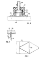
- Fig. 7 is the attachment of the cutting knife 53 in a milled knife receiving groove 123 shown enlarged.
- an L-shaped mounting bracket 125 in profile, in which the outer sides of the two L-leg screwed to the underside of the cutting plate 55 as well also on the inner wall of the cutting knife 53 by means of a weld 127 are fixed.
- FIG. 8 shows a view without or with the cutting knife removed, the in the underside of the cutting plate 55 milled receiving groove 123 with their Contour of an isosceles triangle - according to the one to be cut Piece of dough - clearly visible.
- This knife receiving groove 123 is as it were relevant as an insertion template for all cutting knives that work with each other with the greatest possible Precision must be symmetrical.
- the dough pieces are made on the first conveyor belt table 129 cut out or punched out of the continuous dough sheet.
- the second conveyor belt table 131 is used to store the dough pieces the punch 21 from the first conveyor belt table over the common one Butt or gap 133 between the two tables 129, 131 to the second conveyor belt table 131 transported downwards in the conveying direction 9 by means of the punch 21 or have been moved.
- the second conveyor belt table 131 guides the dough pieces a winding unit. 2 is in the top of the first conveyor belt feed table 129 inserted with a stiffened cutting pad 135 and with an elastomer plate, which acts as a counter bearing or punching part for the cutting knife 53 serves and for sufficient flatness and elasticity of the counterpart.
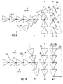
- the punching tool has four matching ones Cutting contours of an isosceles triangular shape each with the base side Bs. This runs in position W for punching parallel to the edge 139 of the continuously fed dough sheet 141 (a clocked feed is fundamental also possible).
- the axis of symmetry s of the isosceles cutting contours 137 runs in position W perpendicular to the edge of the dough band 139 or to the direction of dough transport 9.
- the assembly is started Cutting contours 137 first moved linearly in the transport direction 9 until a certain one Position X is reached, in which there is sufficient space and distance to the remaining, sawtooth-like front edge 143 of the dough band 141 remained is.
- the rotation of the punch or the assembly can start Cutting contours 137 around the between the two middle cutting contours located pivot point D can be initiated.
- the rotation takes place in the drawn Example clockwise 145. With this increasing rotation, which is approximately in or at a level corresponding to the dough sheet 141, the linear movement of the punch 21 continued such that the fulcrum on a line I in the dough transport direction 9 steadily migrates, which is appropriate corresponds to the center line or center axis of the dough sheet 141.
- Half the completion the rotary movement 145 is approximately in the angular range of 45 ° as an intermediate position Y shown.
- the pivot point or the axis of rotation D linear moved further in the direction of transport 9, and the axis of symmetry s came to congruence with the dough sheet center line I.
- the base of the isosceles triangle is again in position X1 parallel to the edge of the dough sheet 139. Since after dough piece storage according to position Z, the rotation in the same Clockwise 145 continued, is now in position X1 Stamping tool 21 with respect to the corresponding position X in Fig. 9 by exactly Rotated 180 ° so that the triangle tips (opposite the base sides Bs) directed downward in Figure 10 (while pointing upward in Figure 9 are). With a further linear return movement 10, the cutting contours can now be made precisely Congruent over the sawtooth-shaped cut out according to FIG. 9 in position W. Bring the end edge 143 of the dough sheet 141 into position, as shown in Fig. 10 labeled W1.
- FIGS. 9 and 10 are those corresponding to the process sequences just explained Movements of the turntable 39 for adjusting the punching tool 21 shown in the sense of the inventive method.
- the top view shown partially broken off in various movement stations Turntable 39 is rotatably connected to the tool carrier 23 and the punch 21 (see above) and adjusts and turns them to the W, W1 position Punch and in position Z for aligned placement.
- the fulcrum or the pivot bearing D moves - analogously to FIGS. 9 and 10 - linearly exactly on the center line I of the dough sheet to be punched out.
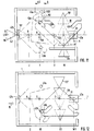
- the base side Bs of the cutting contours 137 runs parallel to Long side and points down in Fig. 11.
- position Z to the aligned Depositing dough pieces 147 is the turntable 39 or the composite Cutting contours 137 rotated 90 ° clockwise 145.
- the base page shows Bs of the isosceles cutting contours 137 in the dough transport direction 9 Forward; the same applies to the base side Bs of the dough pieces 147 with which a downstream winder (not shown) can be loaded immediately can.
- the turntable 39 is through the centering pin 51 exactly centered in the rear centering fork 47a so that the Cutting contours 137 congruent or flush with the sawtooth Precisely punch out the front edge 143 of the dough band 141 individual dough pieces 147 can.
- the carriage 11 is attached to it hinged turntable 39 initially only linearly in the dough transport direction 9 to position X, where the turn of the turntable is 145 mm 39 is initiated.
- the centering pin 51 ensures as long as it is in the rear centering fork 47a (route A - A1), for centered removal the dough pieces and the composite on cutting contours from the front edge of the Dough ribbon.
- position X is the initiation of rotation 145 of the turntable 39 possible.
- the control means of these the corresponding turntable pneumatic cylinder 45 so that the in Transport direction 9 right piston rod 43a is extended and engaged with the corresponding guide recess 41a of the turntable 39 can come.
- 11 is the right piston rod 43a immediately at the entrance of the right guide recess 41a, the first Start section 149 and a second end section at an angle to it 151 has.
- Piston 43a issues an increasing linear displacement of the turntable 39 Turn 145 clockwise, namely from position A2.
- the return movement 10 takes place in a purely linear manner, whereby the rear centering pin 51 in the dough transport direction 9 for symmetrical centering with respect to the center line I in the dough transport direction rear centering fork 47a indent again.
- the punching tool thus has a total rotational movement 145 180 ° clockwise so that the base sides of the isosceles Cutting contours 137 compared to the arrangement according to FIG. 11 of the others Are facing the long side of the dough sheet.
- the centering pin 51 in the rear centering fork 47a with what the new punching position W1 rotated by 180 ° has been reached.
- After punching out There remains a dough band edge on the end face, which has the sawtooth shape in FIG. 10 corresponds to that compared to the sawtooth shape of the dough band edge in FIG. 9 .mu.m Is 180 ° out of phase.
- FIGS. 9 and 10 or 11 and 12 each describe half a working cycle the punching machine, and with another linear movement from the position W1 in Dough transport direction 9, the rotation of the turntable 39 is reversed clockwise, until reaching the storage position in the dough transport direction 9 left piston rod 43b extended and for the return movement 10 then the piston rod 43a of the respective right in the dough transport direction 9 Pneumatic cylinder 45 for the turntable 39 is activated.
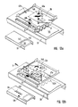
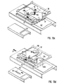
- the complete one The working cycle is illustrated in more detail below with reference to FIGS. 13a-d.
- the punching tool 21 waits in the position W (cf. FIGS. 9 and 11) until the dough sheet 141 is half the length of the base side Bs of the isosceles Contour triangle has been moved in the dough belt conveying direction 9.
- the precise position of stamping tool 21 together with slide 11 or turntable 39 is achieved by fixing via rotary bearing D and centering pin 51. This is necessary in order to punch out the dough pieces 147 with the same contour.
- the punching tool rotates 180 °, which also an absolute symmetry of the punching tool with respect to the axis of symmetry s (see FIGS. 9 and 10) conditionally.
- the movement of the dough band by half the base length can be recorded with a counter, which then has a corresponding Output signal to control means, whereupon the punch stroke is triggered.
- pneumatic cylinder 19 is pressurized and presses it Punching tool 21 with its cutting contours 137 or cutting knives 53 through the dough sheet 141. So that this is completely cut through, the Punch tool pad 33 in the cutting position W, W1 with a flat Plate provided as stiffened cutting pad 135, over which a rubber mat can be laid as a soft pad. This makes it possible for the cutting edge the cutting knife 53 of the punch 21 slightly below the bottom of the dough ribbon.
- the punch stroke cylinder 19 depressurized, and the knives by the spring elements 69, which during of the punching process were tensioned, withdrawn and remain insignificant stand over the lower die part 33.
- the punch stroke is the conveyor belt, if such as a punch lower part is used quietly in order to achieve the greatest possible punching accuracy. Then takes place, as in Fig. 13a with the linear dough transport direction 9 and the rotation 145 indicated clockwise, the transport of the punched out Pieces of dough 147.
- the ejection movement takes place by pressurizing the punching stroke pneumatic cylinder 19 in the reverse, direction pointing away from the surface of the dough sheet. Doing this beforehand pieces of dough 147 located between the cutting knives 53 of these free. Should pieces of dough still be pulled up between the cutting knives 53 the Niederhatlte or located above the dough pieces 147 Scraper plate the dough pieces from the cutting knives 53. According 13b, the turntable 39 becomes the linear return movement after ejection 10 issued against the dough transport direction 9, the rotating plate 39 along with Punching tool 21 is rotated further 90 ° clockwise.
- the punching tool 21 is now in a position opposite the punching position 13a positioned by 180 ° rotated position.
- the base site Bs der isosceles cutting contours or dough pieces 147 points against the in Dough transport direction 9 right edge of the dough.
- the Turntable 39 is given a counter clockwise rotation 146.
- To is the piston rod 43b on the left in the dough transport direction 9 into the associated guide recess 41b extended.
- the right piston rod 43a is in the associated Pneumatic cylinder retracted or kept inactive. The further sequence of movements takes place as explained above, but reversed by 180 °. In doing so the dough pieces 147 as shown in Fig.
- the sawtooth shape of the edge 143b of the dough sheet 141 is 180 ° with respect to the sawtooth front edge 143b according to FIG. 13b out of phase.
Description
Die Erfindung betrifft ein Verfahren zur Herstellung von einzelnen Teigstücken aus
einer kontinuierlichen Teigbahn, indem in den Endabschnitt der Teigbahn eine
schräg oder quer zur Bahnlängsrichtung verlaufende Reihe von separaten, jeweils
in sich geschlossenen Konturen ausgeschnitten wird, welche den Teigstücken
entsprechen, diese in Reihe nebeneinanderliegenden Konturen bzw. Teigstücke
vom Bahnende entfernt und zur Weiterverarbeitung gedreht oder verschwenkt
oder sonstwie positioniert abgelegt werden, gemäß Oberbegriff des Anspruchs 1. Ferner die betrifft die Erfindung eine Vorrichtung
zur Vereinzelung von Teigstücken aus einer kontinuierlichen Teigbahn,
die zur Durchführung des genannten Verfahrens geeignet und mit folgenden
Komponenten versehen ist: mit einem die Teigstückkonturen aufweisenden und
von Antriebsmitteln betätigten und/oder bewegten Stanz- oder sonstigem
Schneidwerkzeug, mit einem diesem gegenüberliegenden Tisch als Auf-, Unter-
oder Ablage für das Teigband und die daraus mittels des Stanz- oder Schneidwerkzeugs
geschnittenen Teigstücke und mit auf die Antriebsmittel einwirkenden
Steuermitteln für die Koordination der zu bewegenden oder anzutreibenden Vorrichtungskomponenten
einschließlich des Stanz- oder Schneidwerkzeugs.The invention relates to a method for producing individual pieces of dough
a continuous dough sheet by inserting a into the end section of the dough sheet
row of separate, each oblique or transverse to the longitudinal direction of the web
is cut out in self-contained contours, which the dough pieces
correspond, these contours or dough pieces lying side by side in a row
removed from the end of the web and rotated or pivoted for further processing
or stored in any other way, according to the preamble of
Derartige Verfahren und Vorrichtungen dienen dem Zuschneiden von Teig für bestimmte Backwaren, die aus Teigstücken gewickelt werden, insbesondere Croissants. Für diese werden gleichschenklige Dreiecke immer so aus dem Teigband ausgeschnitten, daß keine Teigreste entstehen (vgl. zum Beispiel EP 0 382 105 A1). Dies bedingt, daß die Basisseite des gleichschenkligen Dreiecks immer parallel zur Transportrichtung des Teigbandes liegen muß. Allerdings muß zum Wickeln des Teigstücks die Dreieck-Basisseite immer nach vome in Transportrichtung weisend liegen. Deshalb werden Maschinen benötigt, welche das dreieckige Teigstück auf dem Förderband in die genannte, gewünschte Position bringen.Such methods and devices are used to cut dough for certain baked goods that are wound from pieces of dough, in particular Croissants. For these, isosceles triangles are always made from the dough sheet cut out so that no dough remains (see for example EP 0 382 105 A1). This requires that the base side of the isosceles triangle must always be parallel to the direction of transport of the dough sheet. Indeed To wrap the piece of dough, the triangle base side must always face inwards Lying in the direction of transport. Therefore machines are needed, which the triangular piece of dough on the conveyor belt into the desired position bring.
In dieser Hinsicht sind sogenannte Wickel-Croissautomaten" bekannt, das sind Maschinen, die aus dem Teigband Dreiecke ausschneiden und mittels hintereinander angeordneter Förderbänder über Differenzgeschwindigkeiten die geschnittenen Dreiecke auseinander ziehen. Diese werden dann verbandweise auf weitere Förderbänder übergeben, die im rechten Winkel zu den vorausgehenden Förderbändern angeordnet sind. Zwar werden auf diese Weise teuere Spreiz- und Dreheinrichtungen für die Teigstücke erspart. Nachteilig jedoch ist, daß die Transportrichtung um 90° abgelenkt werden muß (beispielsweise wenn direkt auf einen Froster zugearbeitet werden soll). Ferner ist von Nachteil, daß wegen der Lage des Basisschenkels des ausgeschnittenen Dreiecks links und rechts der Maschine je eine Winkeleinrichtung benötigt wird. Bei Verwendung nur eines Wicklers ist der ausgeschnittene Teigling zu wenden, wobei jeweils ein Teigstück-Verband mit einer trockenen Oberseite und einem Teigstück-Verband mit einer feuchten Oberseite in den Wickler einläuft.In this regard, so-called winding croissers are known Machines that cut triangles out of the dough sheet and one behind the other arranged conveyor belts over differential speeds the cut Pull the triangles apart. These are then added to other associations Conveyor belts pass at right angles to the previous conveyor belts are arranged. In this way, expensive spreading and Rotation devices for the dough pieces are spared. The disadvantage, however, is that the direction of transport must be deflected by 90 ° (for example, if directly on one Freezer should be worked). Another disadvantage is that because of the location the base leg of the cut triangle left and right of the machine one angle device is required. When using only one winder, the to cut out the dough piece, each with a dough piece bandage a dry top and a dough bandage with a wet top enters the winder.
Auch in Croissant-Herstellungsmaschinen der eingangs genannten Art, sogenannte "Linien-Croissantomaten", werden Teigstücke in einer speziellen Schneidestation ausgeschnitten und auf einem Förderband der Weiterverarbeitung zugeleitet (vgl. EP 0 382 105 A1). Die ausgeschnittenen Teigstücke werden dabei voneinander "gespreizt", das heißt quer zur Förderrichtung auseinanderbewegt, damit Platz zu ihrem Drehen entsteht. Das Auseinanderrücken und Drehen der Teigstücke erfolgt mittels Greifer in einer Ebene parallel zur Förderband-Oberseite. Der Transport der Teigstücke erfolgt dabei stets geradeaus bzw. in Linie. Die Greifer- und Pick-up-Einrichtungen zum Spreizen und Drehen erfordern eine große Anzahl von Antriebsmotoren, was den Aufwand an Baukomponenten und an die Steuerungssoftware erhöht. Hinzu kommen noch die Schneidstationen, für die besondere Stanzeinrichtungen oder auch Schneidwalzen nebst zugehörigen Antrieben erforderlich sind.Also in croissant production machines of the type mentioned at the beginning, so-called "Line croissant tomatoes" are pieces of dough in a special cutting station cut out and sent for further processing on a conveyor belt (see EP 0 382 105 A1). The cut pieces of dough are separated from each other "spread", that is, moved apart across the conveying direction, thus Space for their turning arises. Moving apart and turning the dough pieces takes place by means of a gripper in a plane parallel to the top of the conveyor belt. The dough pieces are always transported straight or in a line. The Gripper and pick-up facilities for spreading and turning require a large one Number of drive motors, which means the effort in terms of construction components and the control software increased. Added to this are the cutting stations for which special punching devices or cutting rollers and associated drives required are.
Beiden bekannten Systemen ist der Nachteil gemeinsam, daß das Teigstück nach dem Stanzen/Schneiden noch relativ lang am Teigband verbleibt, bevor es durch Förder-/Spreizmittel vom Teigband wegbewegt wird. Dadurch können vor allem bei bestimmten Teigen die Schnittflächen wieder verkleben. The disadvantage of both known systems is that the dough piece after the punching / cutting remains relatively long on the dough sheet before it is through Conveyor / spreading means is moved away from the dough sheet. Above all, this can glue the cut surfaces again for certain doughs.
EP-A-0 482 917 offenbart ein Verfahren und eine Vorrichtung zum Vereinzeln und
Ausrichten von Croissant-Teigstücken. Dazu wird die Verwendung von
Greifklauen 51 mit vorspringenden, in den Teig eindringenden Stiften (vgl. Figur 2)
vorgeschlagen. Diese Stift-Greifer werden sowohl bei der
Vereinzelungsvorrichtung 5 als auch der Ausrichtvorrichtung 6 (vgl. Figur 2)
eingesetzt. Das Eindringen der Stifte 62 in das Teigstück zu dessen Ausrichtung
ist deutlich in Figur 4 gezeigt. Vor allem ist hieraus erkennbar, daß die Stiftgreifer
51 bzw. 62 ohne Schneidwirkung arbeiten. Die Stiftgreifer 51 bzw. 62 sind einzig
dafür vorgesehen, bereits fertig geschnittene Teigstücke im weiteren Verlauf ohne
Schneiden auseinander zu bewegen und auszurichten. Also wird das Vereinzeln
und Ausrichten der bereits geschnittenen Teigstücke mit besonders ausgebildeten
Greifern mit vorspringenden, in die Teigstücke eindringenden Stiften
bewerkstelligt.EP-A-0 482 917 discloses a method and an apparatus for separating and
Aligning croissant dough pieces. The use of
Dem vorstehend diskutierten Stand der Technik ist der Nachteil gemeinsam, daß
das Schneiden der Teigstücke einerseits und das Vereinzeln,
Auseinanderbewegen und Ausrichten der Teigstücke andererseits mit jeweils
separat zugeordneten Einrichtungen (Schneidwalze aus EP-A-0 382 105,
Vereinzelungseinrichtung 5 und Ausrichteinrichtung 6 aus EP-A-0 482 917)
bewerkstelligt werden muß. Dies führt nicht nur zu einer aufwendigen,
umfangreichen Gerätetechnik mit in großer Zahl anzutreibenden und zu
koordinierenden Komponenten, vielmehr ergibt sich auch eine Zeitverzögerung
zwischen dem Vorgang des Schneidens und dem Vorgang des Greifens zum
Vereinzeln und Ausrichten der Teigstücke. Während dieser Zeitverzögerung kann
es leicht dazu kommen, daß die frisch geschnitten und noch feucht
aneinanderliegenden Kanten benachbarter Teigstücke sich wieder verbinden,
miteinander verkleben usw., was den nachfolgenden Vereinzelungsvorgang
erschwert und zudem das ästhetische Aussehen der Teigstücke mindert. The disadvantage of the prior art discussed above is that
cutting the pieces of dough on the one hand and separating them,
Moving apart and aligning the dough pieces on the other hand with each
separately assigned devices (cutting roller from EP-A-0 382 105,
Separating
Der Erfindung liegt die Aufgabe zugrunde, unter Vermeidung der oben genannten Nachteile für den Teigtransport in Linie ein Verfahren und eine Vorrichtung zum Ausschneiden von Teigstücken aus kontinuierlichen Teigbändern sowie zum ausgerichteten Ablegen der ausgeschnittenen Teigstücke für die Weiterverarbeitung zu schaffen, bei der eine geringe Anzahl an Funktions- bzw. Baukomponenten und ein geringer Herstellungs- und Konstruktionsaufwand, insbesondere was die Teigstückführung angeht, notwendig ist Auch soll ein Verkleben der Teigstücke miteinander unmittelbar nach ihrem Zerschneiden verhindert sein.The invention has for its object, while avoiding the above Disadvantages for the transport of dough in line, a method and an apparatus for Cutting dough pieces out of continuous dough bands as well as for aligning them Place the cut dough pieces for further processing to create a small number of functional or structural components and a low manufacturing and design effort, especially what the Dough piece guidance is concerned, it is also necessary to glue the dough pieces with each other immediately after being cut up.
Zur Lösung wird das im Anspruch 1 angebene Verfahren erfindungsgemäß vorgeschlagen. Nach der Erfindung wird also
das eine oder werden die mehreren Stanzmittel, sei es ein Verbund von
Schneidkonturen im Rahmen eines Stanzwerkzeugs, nicht nur zum
Ausschneiden der Teigstücke, sondern auch zum Transport, zum Verschieben
und zur Bewegung der ausgeschnittenen Teiglinge verwendet. Teuere Spreiz- und
Dreheinrichtungen mit automatischen Greifersystemen lassen sich dabei einsparen.
Wenn erfindungsgemäß ein oder mehrere
Stanzwerkzeuge jeweils mit einem vorzugsweise länglichen Oberteil verwendet
werden, das einen oder mehrere die Konturen erzeugende Schneidabschnitte zur
Erzeugung der Teigstückreihe aufweist, läßt sich dieser Verband von Teigstücken
zwischen den Schneidelementen des Stanzwerkzeug-Oberteils halten, führen und
verschieben. Eine längliche Form für das Oberteil ist deshalb zweckmäßig, weil
sich dann mehrere Schneidabschnitte jeweils mit einer Teigstück-Kontur aneinanderreihen
lassen, auch in Transportrichtung hintereinander. Dazu ist es vorteilhaft,
daß unmittelbar nach dem Schneiden bzw. Stanzen der Teigstückkonturen in das
Teigbandende der Druck auf das Stanzwerkzeug-Oberteil gegen das zugehörige
Unterteil soweit zurückgenommen wird, daß das Oberteil mit seinen Schneidkanten
auf der Oberfläche des Unterteils gleiten und/oder darüber bewegt werden
kann. Dadurch läßt sich der ausgeschnittene Teigstück-Verband oder auch ein
einziges Teigstück mit einem einzelnen Schneidmittel besonders leicht vom Teigbandende
über eine Oberfläche oder -seite entfernen, drehen oder sonstwie positionieren.To solve this, the method specified in
Gemäß einer Erfindungsausbildung wird die Teigstückkontur im Folgeschnittverfahren hergestellt: Eine vor den beweglichen Stanzwerkzeugen installierte, stationäre Stanzeinrichtungschneidet beispielsweise die Basis einer gleichschenklig dreieckförmigen Teigstückkontur, während die Schenkel mit dem zur Teigstückbewegung eingesetzten Schneidmitteln geschnitten werden. Bei Folgeschnittwerkzeugen ist es sinnvoll, das Teigstück zusätzlich mit Pickem zu fassen, da die Kontur des Stanzwerkzeugs nicht geschlossen ist.According to an embodiment of the invention, the dough piece contour is in the follow-up cutting process manufactured: one in front of the movable punching tools installed, stationary punching device cuts, for example the base of an isosceles triangular dough contour, while the Cut the leg with the cutting means used to move the dough piece become. With follow-up cutting tools, it makes sense to add the dough piece to grasp with Pickem, since the contour of the punching tool is not closed is.
Im Rahmen einer Erfindungsausbildung muß das Stanzwerkzeug zur Fortbewegung der Teigstücke nicht gedreht werden. Zum Beispiel bei rechteckigen, quadratischen oder runden Produkten, wo Drehen keinen Sinn machen würde, genügte eine nur lineare Fortbewegung.As part of an invention training, the punching tool not be turned to move the dough pieces. For example with rectangular, square or round products where turning doesn't make sense linear movement would suffice.
Der Durchsatz an ausgeschnittenen und ausgerichteten Teigstücken läßt sich erhöhen, wenn nach einer Ausbildung des erfindungsgemäßen Verfahrens mehrere, möglichst viele Stanzmittel jeweils mit einer Schneidkontur für die Teigstückform in Transportrichtung nebeneinander und/oder hintereinander im Teigband-Endbereich angeordnet und im Verbund miteinander oder auch vereinzelt zueinander synchronisiert und/oder koordiniert betätigt sowie bewegt werden. Dieser Gedanke läßt sich durch die oben angesprochene, längliche Form für das Stanzwerkzeug-Oberteil, worin mehrere Schneidmittel einstückig aneinandergereiht sein können, in der Praxis zweckmäßig umsetzen.The throughput of cut and aligned dough pieces can be increased if after one embodiment of the method according to the invention, as many punching agents as possible, each with a cutting contour for the shape of the dough in the transport direction next to each other and / or one behind the other in the end of the dough band arranged and in association with each other or also isolated from each other synchronized and / or coordinated operated and moved. This Thought can be through the above-mentioned elongated shape for the Punching tool upper part, in which several cutting means are lined up in one piece can be implement in practice.
Die oben genannte Erfindungsaufgabe läßt sich bei dem eingangs genannten Verfahren nach einer zusätzlichen Ausbildung der bisher erläuterten Verfahrenserfindung dahingehend lösen, daß die Teigstücke nach ihrem Ausschneiden in ihrer Anordnung und/oder in ihrem Verband bzw. ihrer Reihe belassen werden, und mittels des oder der Schneidmittel diese Teigstück-Reihe oder -Anordnung als Ganzes vom Bahnende entfernt und gedreht und dann abgelegt wird, wonach die Schneidmittel in ihre Ausschneideposition zum (stirnseitigen) Bahnende zuruckbewegt und wieder gedreht werden. Damit ist auch dem eingangs genannten, bei gattungsgemäßen Verfahren angestrebten Ziel, einen Teigstück-Transport in Linie zu schaffen, Rechnung getragen, insbesondere bei der Croissantherstellung, für die gleichschenklige Teigdreiecke ausgeschnitten werden, läßt sich dabei die Dreieck-Basisseite als in Transportrichtung weisende Stimseite positionieren. Dabei ist die der Basisseite gegenüberliegende Dreiecksspitze nach rückwärts entgegen der Teigtransportrichtung gewandt.The above-mentioned object of the invention can be done with the above Procedure after additional training solve the process invention explained so far that the Pieces of dough after being cut out in their arrangement and / or in their bandage or their series are left, and by means of the cutting means or this row or arrangement of dough pieces as a whole is removed from the end of the web and is rotated and then deposited, after which the cutting means in their cut-out position be moved back to the (end) web end and rotated again. This is also the aim mentioned in the generic method Goal to create a piece of dough in line, especially in croissant production, for the isosceles triangles the triangle base side can be cut out as in the transport direction Position the pointing face. The base side is opposite Triangle tip turned backwards against the direction of dough transport.
Nach einer Konkretisierung der allgemeinen, erfinderischen Grundidee werden in dem Zeitraum zwischen dem Ausschneiden der Teigstücke und deren Ablegen die die ausgeschnittenen Teigstücke mit sich führenden Schneidmittel zunächst vom Bahnende linear entfernt und dann gedreht; nach dem Teigstück-Ablegen wird dieser Ablauf umgekehrt wiederholt, bis die Schneidmittel wieder über das Teigbahnende angelangt sind. Bei dieser Bewegungsfolge wandert der Drehpunkt oder die Drehachse des Schneidmittel-Verbundes in Transportrichtung vom Teigbandende weg und wieder zurück.After concretizing the general, inventive basic idea, in the period between cutting out the dough pieces and putting them down the cutting pieces of dough with cutting means leading first linearly removed from the end of the web and then rotated; after putting down the dough piece this process is repeated in reverse until the cutting means over the Have reached the end of the dough sheet. The fulcrum moves during this sequence of movements or the axis of rotation of the cutting compound in the direction of transport from the end of the dough sheet away and back again.
Im Rahmen der Erfindung können die Teigstücke an sich beliebige Formen aufweisen. In der Praxis jedoch finden meist im Zusammenhang mit der Croissant-herstellung die Konturen eines gleichschenkligen Dreiecks oder eines Trapezes Anwendung, welche gegenüber einer Mittelachse symmetrisch sind. Wegen der Forderung nach Restteigfreiheit werden, wie an sich bekannt (vgl. EP 0 382 105 A1), die Teigstücke in der Form eines gleichschenkligen Dreieckes oder eines symmetrischen Trapezes am Teigbahnende so ausgeschnitten, daß der Teigbahn-Endrand etwa sägezahnartig verläuft. In diesem Zusammenhang ist eine Ausbildung des erfindungsgemäßen Verfahrens zweckmäßig, wonach zwischen jedem Teigschneidevorgang das oder die Schneidmittel gegebenenfalls im Verbund miteinander um 180° in alternierender Richtung gedreht werden. Dadurch ist es möglich, daß die Schneidkonturen des Schneidwerkzeugs sich mit dem jeweils entstandenen, sägezahnförmigen Teigbahn-Endrand decken, der nach jedem Schneidvorgang entsprechend einer 180°-Phasenverschiebung bzw. einer Achsenspiegelung neu entsteht.Within the scope of the invention, the dough pieces can have any desired shape. In practice, however, mostly take place in connection with croissant production the contours of an isosceles triangle or a trapezoid Application which are symmetrical with respect to a central axis. Because of the As is known per se, demands for the remaining dough being free (cf. EP 0 382 105 A1), the dough pieces in the shape of an isosceles triangle or a symmetrical trapezoid at the end of the dough sheet so that the end of the dough sheet runs approximately sawtooth-like. In this context an embodiment of the method according to the invention is expedient, after which each dough cutting process or the cutting means, if necessary Can be rotated 180 ° in an alternating direction. Thereby it is possible that the cutting contours of the cutting tool with cover the resulting sawtooth-shaped dough sheet end edge, the after each cutting process according to a 180 ° phase shift or a mirror image is newly created.
Zur Lösung der obigen Erfindungsaufgabe wird bei einer Vorrichtung mit den eingangs genannten Merkmal erfindungsgemäß vorgeschlagen, das Stanz- werkzeug erfassende Führungsmittel vorzusehen, die derart mit den Antriebs- und/oder Steuermitteln gekoppelt sind und parallel zur Tischoberseite verlaufen, daß das Stanzwerkzeug mit den ausgeschnittenen Teigstücken direkt auf und/oder entlang der Tischoberseite gleiten kann und vom Teigbahnende entfembar und dreh- oder verschwenkbar ist. Diese Bewegungen verlaufen in einer Ebene parallel zur Tischoberseite und quer oder schräg zur Schneidrichtung. Die oben zum erfindungsgemäßen Verfahren genannten Vorteile gelten hier entsprechend. Insbesondere werden die ohnehin notwendigen Stanz- werkzeuge nicht nur zum eigentlichen Zweck des Ausschneidens von Teigstücken, sondem auch zu deren Transport und Ausrichtung zusätzlich ausgenutzt. Dies erspart die Anordnung separater, zusätzlicher Funktionskomponenten wie Greifer. Zudem lassen sich die frisch geschnittenen Teigstücke rechtzeitig vom Teigbahnende wegbewegen, bevor sie miteinander verkleben.To solve the above object of the invention in a device with the above mentioned feature proposed according to the invention, the punching to provide tool-capturing guide means that are so connected to the drive and / or control means are coupled and run parallel to the table top, that the punch with the cut dough pieces can slide directly on and / or along the top of the table and from the end of the dough sheet is removable and rotatable or pivotable. These movements run in a plane parallel to the top of the table and across or at an angle to the cutting direction. The advantages mentioned above for the method according to the invention apply here corresponding. In particular, the punching tools not only for the actual purpose of cutting out Pieces of dough, also used to transport and align them. This saves the arrangement of separate, additional functional components like grabs. In addition, the freshly cut dough pieces can be timely move away from the end of the dough sheet before they stick together.
Zur Erhöhung der Transport- und Gleitfähigkeit sowie zur Verminderung von Verschleiß und mechanischen Beschädigungen ist nach einer Ausbildung der erfindungsgemäßen Vorrichtung vorgesehen, daß die Antriebsmittel eine zum Teigband gerichtete Druck- oder Betätigungseinrichtung und eine dieser entgegengerichtete oder entgegenwirkende Rückstelleinrichtung aufweisen, mit denen jeweils die Schneidelemente des Stanzwerkzeugs verbunden sind. Dabei ist der von der Rückstelleinrichtung für die Schneidelemente ausgelöste Rückweg so bemessen, daß die Schneidelemente außer formschlüssigen Eingriff mit der Tischoberseite geraten, das Stanzwerkzeug jedoch mit den ausgeschnittenen Teigstücken in reibschlüssigen Eingriff und/oder Gleitkontakt mit der Tischoberseite bleibt. Dadurch ist gewährleistet, daß die Teigstücke immer zwischen dem Stanzwerkzeug und der Tischoberseite (welche beim Stanzen das Stanz-Unterteil bildet) gehalten, geführt und verschoben werden können.To increase the transport and sliding ability and to reduce wear and mechanical damage is after training the invention Device provided that the drive means one to the dough sheet directed pressure or actuating device and one of these opposed or have counteracting reset device, with each the cutting elements of the punch are connected. there is the return path triggered by the reset device for the cutting elements dimensioned so that the cutting elements except positive engagement with the Top of the table, but the punch with the cut Pieces of dough in frictional engagement and / or sliding contact with the Top of the table remains. This ensures that the dough pieces are always between the punching tool and the table top (which at the Punching forms the lower punch part) held, guided and moved can.
Eine der erfindungsgemäßen Verfahrensweise entsprechende oder angepaßte Struktur der Führungsmittel für das Stanzzeug besteht darin, daß diese eine vom Teigbahnende in oder parallel zur Transportrichtung zum Ablageplatz der Teigstücke verlaufende Linearführung aufweisen, in der ein das Stanzwerkzeug tragender Schlitten hin- und herverschiebbar gelagert ist. Im oder am Schlitten ist eine Drehlagerung ausgebildet, an der das Stanzwerkzeug drehbar angebracht ist. Entsprechend sind die Antriebsmittel mit einem Linearantriebsmodul zur Bewegung des Schlittens und einem Drehantriebsmodul zur Drehung des Stanzzeugs zwecks Ausrichtung der abzulegenden Teigstücke versehen, wobei diese Module zu ihrer Koordination und/oder Synchronisation untereinander und/oder mit etwaigen Teigstück- oder Teigbahn-Fördermittein mit den Steuermitteln gekoppelt sind.One corresponding or adapted to the procedure according to the invention The structure of the guide means for the punching tool is that this one from the end of the dough in or parallel to the direction of transport to the storage place of the dough pieces running linear guide in which a Punching tool-carrying slide can be moved back and forth is. A rotary bearing is formed in or on the slide, on which the punching tool is rotatably attached. The drive means are corresponding with a linear drive module for moving the carriage and one Rotary drive module for rotating the punch for alignment of the pieces of dough to be put down, these modules for their coordination and / or synchronization with each other and / or with any pieces of dough or dough sheet conveying means are coupled to the control means.
Zur Einsparung von Antriebskomponenten ist mit Vorteil das Drehantriebsmodul passiv ausgebildet, dergestalt, daß es vom Linearantrieb bzw. dem davon getriebenen Schlitten über Mitnehmerelemente um die Drehachse der Drehlagerung in Drehung versetzt wird. Andererseits ist es denkbar, auch für den Drehantrieb - wie für den Unearantrieb - gesonderte Antriebseinheiten, beispielsweise einen elektrischen Rotationsmotor vorzusehen. Solchenfalls wäre als Linearantrieb ein elektrischer Linearmotor zweckmäßig, weil dann beide Elektromotoren über ein gemeinsames Kommunikationssystem von den Steuermitteln geleitet und/oder geregelt werden könnten.The rotary drive module is an advantage for saving drive components passively formed, such that it is driven by the linear drive or Carriage over driver elements around the axis of rotation of the rotary bearing in Rotation is offset. On the other hand, it is also conceivable for the rotary drive - how for the Unearantrieb - separate drive units, for example an electric one To provide a rotary motor. In this case, an electric linear actuator would be used Linear motor expedient, because then both electric motors have a common one Communication system directed and / or regulated by the control means could become.
Der Lösung der obigen Erfindungsaufgabe dient auch ein mit der angesprochenen, erfindungsgemäßen Vorrichtung kombinierbares Stanzwerkzeug, das sich durch eine erste und eine zweite Halteplatte als Grundstruktur auszeichnet, die gegeneinander in Stanzhubrichtung (rück-)verstellbar verbunden sind. Die erste Halteplatte trägt die Schneidelemente mit den die Teigstückkontur bildenden bzw. erzeugenden Schneidkanten, und die zweite Halteplatte ist mit Elementen zum Ausstoßen und/oder Niederhalten von Teig an oder zwischen den Schneidelementen versehen. Dazu sind die Teig-Ausstoß- und/oder Halteelemente unmittelbar neben den Schneidelementen und/oder an diesen gleitbar mit einem Verstellhub angeordnet, der sich beidseits der Schneidkante des Schneidelements erstreckt. Mit diesem Stanzwerkzeug in zweiteiliger, in sich verstellbarer Grundstruktur lassen sich die Ausstoß- und/oder Halteelemente für eine zuverlässige Ablage der Teigstücke und für eine teigfreie Rückführung der Schneidelemente zum stirnseitigen Teigbahnende einsetzen.The solution of the above inventive task is also used with the The device according to the invention can be combined with a punching tool characterized by a first and a second holding plate as the basic structure, the are connected to one another in the punching stroke direction so as to be (re) adjustable. The first Holding plate carries the cutting elements with the dough piece contour or generating cutting edges, and the second holding plate is provided with elements for Ejecting and / or holding down dough on or between the cutting elements Mistake. For this purpose, the dough ejection and / or holding elements are immediate in addition to the cutting elements and / or slidable with an adjustment stroke arranged, which extends on both sides of the cutting edge of the cutting element. With this punch in a two-part, self-adjustable basic structure the ejection and / or holding elements for reliable storage of the dough pieces and for a dough-free return of the cutting elements to the front Insert the end of the dough sheet.
Weitere Einzelheiten, Merkmale und Vorteile auf der Basis der Erfindung ergeben sich aus den Unteransprüchen sowie der nachfolgenden Beschreibung eines bevorzugten Ausführungsbeispiels der Erfindung anhand der Zeichnungen. Diese zeigen in:
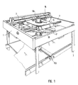
- Fig. 1
- eine perspektivische Seitenansicht auf die erfindungsgemäße Maschine zum Ausstanzen, Drehen und Positionieren von ausgeschnittenen Teig-Dreiecken mit Maschinengestell, Linearführungssystem im oberen Bereich, darin geführten Schlitten u.a.
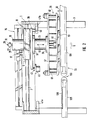
- Fig. 2
- die erfindungsgemäße Maschine in Seitenansicht,
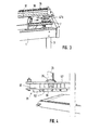
- Fig. 3
- eine perspektivische Seitenansicht auf den stirnseitigen Endbereich der Maschine mit Zentriergabel,
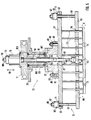
- Fig. 4
- eine perspektivische Seitenansicht auf den unteren Maschinenteil mit Stanzwerkzeug,
- Fig. 5
- die erfindungsgemäße Anordnung des Stanzwerkzeugs, Werkzeugträgers und Schlittens in der Maschine,
- Fig. 6
- eine Schnittansicht nach der Linie VI - VI in Fig. 5,
- Fig. 7
- die Einzelheit Vll aus Fig. 5 in vergrößerter Darstellung
- Fig. 8
- eine Ansicht auf die Schneidplatte des Stanzwerkzeugs auf der Unterseite ohne Schneidmesser,
- Fig. 9
- in Draufsicht die Teigstück-/Stanzwerkzeug-Bewegungsabfolge vom Ausschneiden bis zum ausgerichteten Ablegen nach der Erfindung,
- Fig. 10
- in entsprechender Ansicht die Teigstück-/Stanzwerkzeug-Bewegungsfolge von der Ablage bis zum Ausschneidvorgang,
- Fig. 11
- die Fig. 9 entsprechenden Bewegungsstationen des Stanzwerkzeugs in der Maschine nach Ausschneiden in Teigtransportrichtung in Draufsicht,
- Fig. 12
- die Fig. 10 entsprechenden Bewegungsstationen des Stanzwerkzeugs in der Maschine nach Teigstück-Ablage entgegen der Teigtransportrichtung, und
- Fig. 13a-d
- jeweils in perspektivischer Darstellung die Wirkungsweise der erfindungsgemäßen Maschine mit den Stanzwerkzeug-Bewegungsstationen eines vollständigen Arbeitszyklus.
- Fig. 1
- a side perspective view of the machine according to the invention for punching, turning and positioning of cut dough triangles with machine frame, linear guide system in the upper area, slide guided therein, among other things
- Fig. 2
- the machine according to the invention in side view,
- Fig. 3
- a perspective side view of the front end area of the machine with centering fork,
- Fig. 4
- a perspective side view of the lower machine part with punching tool,
- Fig. 5
- the arrangement according to the invention of the punching tool, tool carrier and slide in the machine,
- Fig. 6
- 5 shows a sectional view along the line VI-VI in FIG. 5,
- Fig. 7
- the detail Vll from Fig. 5 in an enlarged view
- Fig. 8
- a view of the cutting plate of the punch on the bottom without cutting knife,
- Fig. 9
- in plan view the dough piece / punching tool movement sequence from cutting out to aligned depositing according to the invention,
- Fig. 10
- in a corresponding view the dough piece / punching tool movement sequence from the deposit to the cutting process,
- Fig. 11
- 9 corresponding movement stations of the punching tool in the machine after cutting in the dough transport direction in plan view,
- Fig. 12
- 10 corresponding movement stations of the punch in the machine after dough piece storage against the direction of dough transport, and
- 13a-d
- each in perspective representation of the operation of the machine according to the invention with the punch movement stations of a complete work cycle.
Gemäß Fig. 1 und 2 ist der Rahmen 1 der erfindungsgemäßen Maschine zum
kombinierten Stanzen und Positionieren von Teigstücken über ein Gestell 3 auf
dem Boden oder in einem Maschinenfundament abgestützt. Im oberen Bereich
des Maschinenrahmens 1 ist eine Linearführung 5 mit einer Führungsstange 7
eingebaut, die sich parallel zur Teigtransportrichtung bzw. zur Maschinenseite erstreckt.
Auf der Führungsstange 7 ist ein Schlitten 11 in oder entgegen der Teigtransportrichtung
9 verschiebbar gelagert; im praktischen Ausführungsbeispiel
durchsetzen zwei Führungsstangen 7 den Schlitten 11 über darin ausgebildete,
durchgehende Führungsbohrungen 13. Zur Schlittenführung kann eine an sich
bekannte Kugelbuchsenführung Einsatz finden. 1 and 2, the
Als lineares Antriebsmittel für den Zylinder ist ein im praktischen Ausführungsbeispiel
kolbenstangenloser Pneumatikzylinder 15 oberhalb des Schlittens 11 angeordnet
und gegen den Maschenrahmen 1 abgestützt. Dessen Bewegungshub erstreckt
parallel zur Führungsstange 7 der Schlitten-Linearführung 5. Durch eine
(nicht gezeichnete), übergeordnete Steuerung wird der Pneumatikzylinder 15 zeitgerecht
angesteuert bzw. betätigt, um über Mitnehmerzapfen 17, die sowohl am
Pneumatikzylinder 15 als auch am Schlitten 11 zu deren Führungen quer verlaufend
befestigt sind, den Schlitten 11 in und entgegen der Teigtransportrichtung 9
zu bewegen.As a linear drive means for the cylinder is in a practical embodiment
rodless
Alternativ kann das Linearführungssystem auch durch einen reversierbaren Drehstromantrieb gebildet werden, der den Schlitten durch einen Zahnriemen antreibt. Dabei kann der Schlittenführung beispielsweise als Profilschienenführung ausgeführt sein.Alternatively, the linear guide system can also be reversed Three-phase drive are formed, which drives the carriage through a toothed belt. The slide guide can be used, for example, as a linear guide be executed.
Gemäß Fig. 1 und 2 sind im Schlitten 11 auf der Oberseite ein weiterer Pneumatikzylinder
19 zur Einprägung des Stanzhubs für ein Stanzwerkzeug 21 und auf
der Unterseite ein Werkzeugträger 23 zum Tragen und Halten des Stanzwerkzeugs
21 angebracht. Am oberen, stirnseitigen Ende des Stanzhub-Pneumatikzylinders
19 ist auf einer durchgehenden Mittelstange 25 am oberen
Ende eine Dämpfungsscheibe 27 aufgesetzt (nach Fig. 1 eine Gummi-Dämpfungsfeder
113). Diese läßt sich in Verbindung mit einer von oben auf ein
stirnseitiges vorstehendes Außengewinde 29 der Mittelstange 25 aufgeschraubten
Einstellmutter 31 als Gegenlager zum Einstellen des Abstandes 32 der Schneidelemente
des Stanzwerkzeugs 21 zum Stanzunterteil 33 verwenden. Das
Stanzwerkzeug 21 kann am unteren Ende des Werkzeugträgers 23 über eine
(schematisch dargestellte) Schnellwechseleinrichtung 35 befestigt sein. Damit läßt
sich flexibel auf Teigstück-Formwünsche des Anwenders durch Wechseln des
Stanzwerkzeugs unter Einsatz der entsprechenden Form reagieren. Am oberen
Ende des zylindrischen Werkzeugträgers ist über eine radiale Erweiterung 37 eine
Drehscheibe 39 befestigt. Über diese lassen sich, wie weiter unten ausführlich
dargestellt, aus dem Linearantrieb 15 in Verbindung mit der Linearführung 5
Drehbewegungsabläufe für das Stanzwerkzeug ableiten, die je nach gewünschter
Teigform durch in die Drehscheibe 39 eingeprägte bzw. ausgeschnittene, spezifisch
angepaßte Führungsbahnen realisiert sind. Im konkreten Ausführungsbeispiel
ist dies durch zwei zum Drehpunkt der Drehscheibe 39 symmetrisch angeordnete
Führungsaussparungen 41 realisiert, in die zum gegebenen Zeitpunkt
(siehe unten) die Kolbenstangen 43 von zwei im Maschinenraum 1 gegenüberliegend
angeordneten Pneumatikzylindern 45 zu einem von den (nicht gezeichneten)
Steuerungsmitteln bestimmten Zeitpunkt eingefädelt werden. Dadurch wird
die Drehscheibe 39, wenn sie vom Schlitten 11 linear mitbewegt wird, gleichzeitig
in eine Drehung um ihre Drehachse versetzt, die auch auf das Stanzwerkzeug 21
übertragen wird.1 and 2 are a further pneumatic cylinder in the
Gemäß Fig. 2 sind am hinteren und vorderen Totpunkt des Bewegungshubs des
Schlittens 11 bzw. an den entsprechenden Rück- und Vorderseiten des Maschinenrahmens
1 Zentriergabeln 47a, 47b an den jeweiligen Innenwandungen befestigt,
wie aus Fig. 3 es noch deutlicher hervorgeht. Nach der in Fig. 2 gezeigten
Stellung ist zwischen die beiden Zinken 49 der Zentriergabel 47b für den in Teigtransportrichtung
9 vorderen Totpunkt des Schlittenhubs ein Zentrierzapfen 51
eingerückt, wodurch der Werkzeugträger 23 in oder parallel zur Transportrichtung
in der vorderen Teigstück-Ablageposition geführt und positioniert ist. Entsprechendes
gilt für die hintere Zentriergabel 47a im Zusammenhang mit der Zentrierung
und Fixierung des Werkzeugträgers 23 in Stanzposition. Die Zentrierbolzen
51 für die beiden Zentriergabeln 47a, 47b sind jeweils an der Unterseite der Drehscheibe
39 befestigt. Die vordere Zentriergabel 47b positioniert den Werkzeugträger
so, daß das Stanzwerkzeug 21 mit seiner Längsrichtung parallel zur Teigtransportrichtung
9 verläuft, wohingegen bei Zentrierung durch die hintere Zentriergabel
47a der Werkzeugträger 23 zusammen mit dem Stanzwerkzeug 21 um
90° gedreht für die Stanzposition, mit der Längsrichtung quer zur Teigtransportrichtung
9 verlaufend, gestellt ist (siehe auch weiter unten).2 are at the rear and front dead center of the movement stroke of the
Gemäß Fig. 2 und 4 ist das Stanzwerkzeug 21 in eine Schneidmesser 53 an der
Unterseite tragende Halteplatte 55 und eine darüber angeordnete Basisplatte 57
mit der Schnellwechseleinrichtung 35 auf der Oberseite zum Werkzeugträger 23
untergliedert. Wie auch näher aus Fig. 5 ersichtlich, ist die Schneidplatte 55 gegenüber
der Basisplatte 57 in Stanzhubrichtung 59 mittels Führungssäulen 61 an
den beiden Längsenden des Stanzwerkzeugs 21 verschiebbar geführt. Die Führungssäulen
61 sind an der Oberseite der Schneidplatte 55 starr fixiert und durchsetzen
Führungsbohrungen 63 an den beiden Längsenden der Basisplatte 57. Am
oberen Ende enden die Führungssäulen 61 in Außengewindevorsprünge 65, auf
die jeweils eine Stellmutter 67 aufgeschraubt ist. Mit dieser kann eine die Führungssäule
61 umfassende Elastomerfeder 69 gespannt und der entsprechende
Federweg eingestellt werden. An der oberen und unteren Stirnseite der Elastomerfeder
69 sind jeweils Beilagscheiben 71 angebracht. Durch Einstellung des
Federwegs mittels der Stellmutter 67 läßt sich der Rückhub der Schneidplatte 55
einstellen, damit bei Beendigung des Stanzvorgangs der Stanzhub-Pneumatikzylinder
19 zurückgestellt wird. Die Elastomerfeder 69 ist vorzugsweise
aus Polyurethan hergestellt, und die beiden Beilagscheiben 71 zwischen den
Elastomerfeder-Stirnseiten einerseits und der Stellmutter 67 bzw. der Basisplatten-Oberseite
andererseits dienen der besseren Verteilung des Drucks aus der
Stellmutter 67 auf die Federelemente 69. Mit dem Versetzen des Stanzhub-Pneumatikzylinders
19 in den drucklosen Zustand unmittelbar nach Durchschneiden
des Teigbands in Teigstücke können die Elastomerfedern 69 die
Schneidplatte 55 gegenüber der Basisplatte 57 nach oben in eine Stellung drükken,
in welcher das Stanzwerkzeug 21 mit den ausgeschnittenen Teigstücken
über das Stanzwerkzeug-Unterteil 33 gleiten kann.2 and 4, the
In Fig. 5 ist das Stanzwerkzeug 21 in der Stanzstellung gezeichnet, das heißt, die
Schneidmesser 53 überragen mit ausreichendem Überstand 73 Niederhalteplättchen
75 beispielsweise aus Kunststoff, die an unteren Enden von Führungsstangen
77 befestigt sind und sich jeweils zwischen den einander zugewandten Innenseiten
der die Teigstück-Konturen abbildenden Schneidmesser 53 erstrecken. Am
anderen Ende sind die Führungsstangen 77 an der Unterseite der Basisplatte 57
starr befestigt und durchsetzen von dort aus die Schneidplatte 55 in jeweiligen
Führungsbohrungen 79 bis zu den Niederhalteplättchen 75 am unteren Ende, die
dem Halten der ausgeschnittenen Teigstücke während des Transports auf dem
Stanzwerkzeug-Unterteil 33 und dem Abstreifen und Auswerfen der Teigstücke in
die ausgerichtete Ablageposition (siehe unten) dienen. Bei dieser Anordnung können
sich die Schneidmesser 53 und die Niederhalteplättchen 75 relativ zueinander
auf- und abwärtsbewegen. Werden die Schneidmesser 53 bei entsprechender
Ansteuerung bzw. Betätigung des Stanzhub-Pneumatikzylinders 19 um den Weg
G nach oben bewegt, können sich zwischen den Schneidmessern 53 befindliche-
und gar geklemmte Teigstückpartikel abgestriffen werden. Für den Produktwechsel
ist das Stanzwerkzeug 21 über die Schnellwechseleinrichtung 35 (siehe Fig. 2
oder 4) vom Werkzeugträger 23 abnehmbar gehaltert. Von der Oberseite der Basisplatte
57 beidseits des Werkzeugträgers 23 nach oben ragende Führungsbolzen
81 dienen der Führung des Stanzwerkzeugs 21 in komplementären Langlöchern
des Werkzeugträgers 23 (nicht gezeichnet). Die Höhe der Führungsbolzen
81 ist geringfügig niedriger als die Wanddicke im entsprechenden Aufnahmeteil
des Werkzeugträgers 23, so daß die Basisplatte 57 mittels eines Schrauben- oder
Mutterelements 83 gegen den Werkzeugträger 23 gezogen und fixiert werden.
Beim Hineinscheiben in den Werkzeugträger 23 wird das Stanzwerkzeug 21 von
Tragscheiben 85 unmittelbar unterhalb der Stirnseite der Schrauben/Mutterelemente
83 gehalten. Innerhalb eines als ringartiger Vorsprung ausgebildeten
Zentrierbundes 87, welcher die exakt mittige Position des Stanzwerkzeugs
21 im Werkzeugträger 23 gewährleistet, erstreckt sich die Anschlußstange 89 des
Stanzwerkzeugs nach oben zum Anschlußstück 91 der Kolbenstange 93 des
pneumatischen Stanzhubzylinders 19. Die Verbindung zwischen dem Kolbenstangen-Anschlußstück
91 und der Anschlußstange 89 des Stanzwerkzeugs 21 läßt
sich mittels einer (schematisch angedeuteten) Quer-Schraubverbindung 95 bewerkstelligen.5, the
Gemäß Fig. 5 weist der Werkzeugträger 23 einen den Zentrierbund 87 umgebenden
Schraubblock 97 auf, der auf die Oberseite der Basisplatte 57 des
Stanzwerkzeugs 21 aufgesetzt und über die Führungsbolzen 81 mit Verschraubung
83 damit verbunden ist. Die Anschlußstange 89 sowie das daran angeschraubte
Anschlußstück 91 der Kolbenstange 93 sind in einem Befestigungshohlraum
99 aufgenommen, der innerhalb des Schraubblocks 97 ausgebildet ist.
Er kann als Schlitz ausgeführt sein, über dessen Mantelfläche das Stanzwerkzeug
21 mittels seines Zentrierbunds 87 zentriert angebracht ist. Der Schraubblock 97
ist mit einer Rotationsummantelung 101 verbunden, zum Beispiel verschraubt, die
über Drehlagerstellen 103 gegenüber einer Innebüchse 105 drehbar gelagert ist.
Die Innenbüchse 105 ist auf ihrer oberen Stirnseite mit dem Schlitten 11 an dessen
Unterseite fest verbunden, beispielsweise verschraubt. Die Rotationsummantelung
101 ist am oberen Ende mit der Drehscheibe 39 an oeren Unterseite verbunden,
beispielsweise verschraubt. So kann die Drehscheibe 39, wenn sie vom
Linearantriebssystem ihrer Drehungen ableitet, diese auf den Werkzeugträger 23
bzw. dessen Schraubblock 97 übertragen. Gegenüber der von der Drehscheibe
39 in Rotation versetzten Rotationsummantelung 101 verbleibt der Kern des
Werkzeugträgers 23, die Innenbüchse 105, im Stillstand, weil das Drehmoment
aufgrund der am oberen und unteren Ende der Innenbüchse 105 angebrachten
Drehlagerung 103 nicht übertragen werden kann. Gegen axiales Verschieben ist
die Innenbüchse 105 durch eine Sicherungsscheibe 107 am unteren, stirnseitigen
Ende gesichert, welche das Kolbenstangen-Anschlußstück 91 umgibt. Auf dem
Schlitten 11 montiert ist der Stanzhub-Pneumatikzylinder 19 zur Herbeiführung
von Stanzbewegungen der Schneidplatte 55 mit den Schneidmessern 53. Die
Stanztiefe läßt sich mittels einer Zylinder-Stellmutter 109 einstellen, welche auf
einem Außengewindevorsprung 111 aufgeschraubt ist, der stirnseitig aus dem
pneumatischen Stanzhubzylinder 19 am oberen Ende vorspringt. Eine unmittelbar
an der unteren Stirnseite der Zylinderstellmutter 109 angeordnete Gummifeder
113 dient der Bewegungsdämpfung beim Fahren in die Endlage.5, the
Damit sich die Drehbewegung der Rotationsummantelung 101 des Werkzeugträgers
3 nebst der des Schraubblocks 97 sich nicht auf die Kolbenstange 93 und
dessen Anschlußstück 91 des pneumatischen Stanzzylinders 19 überträgt, ist
gemäß Fig. 6 die Anschlußstange 89 des Stanzwerkzeugs 21, die an ihrem unteren
Ende eine stempelartige Erweiterung 115 aufweist, damit in einem Kunststoffgehäuse
117 aufgenommen und drehbar gelagert. Dieses ist auf der Oberseite
der Schneidplatte 55 befestigt, beispielsweise mittels Schraubstellen 119. Innerhalb
des Kunststoffgehäuses 117 unmittelbar unterhalb der Unterseite der Stempelerweiterung
115 befindet sich eine Gleitlagerscheibe 121, welche der axialen
Kraftübertragung vom pneumatischen Stanzhubzylinder 19 auf die Schneidplatte
55 des Stanzwerkzeugs 21 dient. Auch letztere ist - wie das Gehäuse 117 - insbesondere
aus Gründen der Geräuschdämpfung und Reibung mit Kunststoff hergestellt.
Die Basisplatte 57 des Stanzwerkzeugs 21 ist über die Schraubverbindung
81, 83, 85 fest mit dem drehbaren Teil 97, 101 des Werkzeugträgers 23 verbunden.
Die sich gegebenenfalls drehende Schneidplatte 55 läßt sich durch den von
der Drehung entkoppelten pneumatischen Stanzhubzylinder 19 auf- und niederbewegen,
wobei sich die Führungssäulen 61 in den Führungsbohrungen 63 der
Basisplatte 57 entsprechend mitheben oder -senken.So that the rotational movement of the
In Fig. 7 ist die Befestigung der Schneidmesser 53 in einer eingefrästen Messeraufnahmenut
123 vergrößert dargestellt. Zur Befestigung und Stabilisierung dient
ein im Profil L-förmiger Befestigungswinkel 125, bei dem die Außenseiten der beiden
L-Schenkel sowohl an der Unterseite der Schneidplatte 55 verschraubt als
auch an der Innenwandung des Schneidmessers 53 mittels einer Schweißstelle
127 fixiert sind.In Fig. 7 is the attachment of the cutting
Die Fig. 8 zeigt eine Ansicht ohne bzw. mit entferntem Schneidmesser, wobei die
in die Unterseite der Schneidplatte 55 eingefräste Aufnahmenut 123 mit ihrer
Kontur eines gleichschenkligen Dreiecks - entsprechend des auszuschneidenden
Teigstücks - deutlich sichtbar wird. Diese Messeraufnahmenut 123 ist gleichsam
als Einsetzschablone für alle Schneidmesser relevant, die zueinander mit größtmöglicher
Präzision symmetrisch liegen müssen.8 shows a view without or with the cutting knife removed, the
in the underside of the cutting
Gemäß Fig. 1 und 2 ist unterhalb des Maschinenrahmens 1 das Stanzwerkzeug-unterteil
33 angeordnet, welches im konkreten Ausführungsbeispiel durch einen
ersten Zuführ-Förderbandtisch 129 und einem zweiten Wegführ-Förderbandtisch
131 realisiert ist. Auf dem ersten Förderbandtisch 129 werden die Teigstücke aus
dem kontinuierlichen Teigband ausgeschitten bzw. ausgestanzt. Zu diesem Zweck
ist wenigstens der erste Förderbandtisch 129 mit einer schnittfesten Oberfläche
versehen. Der zweite Förderbandtisch 131 dient der Ablage der Teigstücke aus
dem Stanzwerkzeug 21, die vom ersten Förderbandtisch über den gemeinsamen
Stoß bzw. Spalt 133 zwischen den beiden Tischen 129, 131 zum zweiten Förderbandtisch
131 in Förderrichtung 9 abwärts mittels des Stanzwerkzeugs 21 transportiert
bzw. verschoben wurden. Nach Ausstoßen der Teigstücke und Zurückfahren
des Stanzwerkzeugs 21 führt der zweite Förderbandtisch 131 die Teigstücke
einer Wickeleinheit zu. Gemäß Fig. 2 ist in die Oberseite des ersten Förderband-Zuführtisches
129 mit einer versteiften Schneidunterlage 135 eingesetzt und mit
einer Elastomerplatte belegt, die als Gegenlager oder Stanzwerkzeug-Unterteil für
die Schneidmesser 53 dient und für eine ausreichende Ebenheit und Elastizität
des Gegenlagers sorgt.1 and 2 is the lower part of the punching tool below the
Nachfolgend wird das erfindungsgemäße Verfahren im Zusammenhang mit der Funktionsweise der erfindungsgemäßen Vorrichtung erläutert.The method according to the invention is described below in connection with the Operation of the device according to the invention explained.
In den Fig. 9 und 10 ist ein vollständiger Bewegungszyklus der Schneidkontur des
Stanzwerkzeugs für den konkreten Anwendungsfall der Croissant-Herstellung aus
Teigstücken mit der Kontur eines gleichschenkligen Dreiecks gezeigt. Im gezeichneten
Ausführungsbeispiel besitzt das Stanzwerkzeug vier übereinstimmende
Schneidkonturen gleichschenkliger Dreiecksform jeweils mit der Basisseite Bs.
Diese verläuft in der Stellung W für Ausstanzen parallel zum Rand 139 des kontinuierlich
zugeführten Teigbandes 141 (eine getaktete Zuführung ist grundsätzlich
auch möglich). Die Symmetrieachse s der gleichschenkligen Schneidkonturen 137
verläuft in Stellung W senkrecht zum Teigbandrand 139 bzw. zur Teigtransportrichtung
9. Während des Ausstanzens eines Verbands gleichschenklig dreieckförmiger
Teigstücke wird das das Teigband 139 tragende Förderband zweckmäßig
kurz angehalten. Nach Vollendung des Stanzvorgangs wird der Verbund an
Schneidkonturen 137 zunächst linear in Transportrichtung 9 bewegt, bis eine bestimmte
Stellung X erreicht ist, in der ausreichend Platz und Entfernung zum verbliebenen,
sägezahnartig ausgestanzten Stirnrand 143 des Teigbandes 141 verblieben
ist. Nun kann die Drehung des Stanzwerkzeugs bzw. des Verbunds an
Schneidkonturen 137 um den zwischen den beiden mittleren Schneidkonturen
gelegenen Drehpunkt D eingeleitet werden. Die Drehung erfolgt im gezeichneten
Beispiel im Uhrzeigersinn 145. Mit dieser zunehmenden Drehung, die etwa in bzw.
auf einer dem Teigband 141 entsprechenden Ebene erfolgt, wird gleichzeitig die
lineare Fortbewegung des Stanzwerkzeugs 21 derart fortgesetzt, daß der Drehpunkt
auf einer Linie I in Teigtransportrichtung 9 stetig fortwandert, die zweckmäßig
der Mittellinie bzw. Mittelachse des Teigbandes 141 entspricht. Die halbe Vollendung
der Drehbewegung 145 etwa im Winkelumfang von 45° ist als Zwischenstellung
Y dargestellt. Mit Weiterführung bzw. Vollendung der Drehung nach
Durchlaufen eines Winkels von 90° aus der Stellung W/X in die Stellung Z für
Teigstückablage ist auch gleichzeitig der Drehpunkt bzw. die Drehachse D linear
weiter in Transportrichtung 9 verschoben worden, und die Symmetrieachse s ist
zur Deckung mit der Teigband-Mittellinie I gekommen. Sind in der Stellung Z die
innerhalb der Schneidkonturen 137 mitgeführten Teigstücke beispielsweise mittels
der Niederhalteplättchen 75 (vgl. Fig. 5) ausgestoßen worden, wird die Linearbewegung
für das Stanzwerkzeug 21 umgekehrt in eine Gegenrichtung 10 entgegen
der Teigtransportrichtung 9 (Fig. 10). Mit zunehmender Rückbewegung 10 wird
erneut für das Stanzwerkzeug 21 die Drehung 145 im Uhrzeigersinn eingeleitet
bzw. weitergeführt, bis die mit Y1 bezeichnete Zwischendrehstellung gemäß Fig.
10 erreicht ist. Mit weiterer Bewegung des Stanzwerkzeugs 21, wobei die Rück-Linearbewegung
10 und die Drehbewegung 145 einander überlagert sind, wird
schließlich die Stellung X1 gemäß Fig. 10 erreicht, welche der Stellung X in Fig. 9
entspricht. Beide Stellungen zeichnen sich dadurch aus, daß die Dreieck-Symmetrieachse
s nunmehr senkrecht zur Teigband-Mittellinie I liegt. Während
des gesamten Bewegungsablaufs ist der Stanzwerkzeug-Drehpunkt D stets auf
der Mittellinie I zunächst nach Fig. 9 in Teigtransportrichtung 9 und nach Teigstück-Ablage
in Teigtransport-Gegenrichtung 10 (zurück-) gewandert. Die Basis
des gleichschenkligen Dreiecks liegt in der Stellung X1 wieder parallel zum Teigbandrand
139. Da nach Teigstück-Ablage gemäß Stellung Z die Drehung im gleichen
Uhrzeigersinn 145 fortgesetzt wurde, ist nun in der Stellung X1 das
Stanzwerkzeug 21 gegenüber der entsprechenden Stellung X in Fig. 9 um genau
180° gedreht, so daß die Dreieckspitzen (den Basisseiten Bs gegenüberliegend)
in Fig. 10 nach unten gerichtet sind (während sie in Fig. 9 nach oben gerichtet
sind). Mit weiterer Linear-Rückbewegung 10 können nun die Schneidkonturen genau
deckungsgleich über den nach Fig. 9 in Stellung W ausgeschnittenen, sägezahnförmigen
Stirnrand 143 des Teigbandes 141 in Stellung kommen, wie in Fig.
10 mit W1 bezeichnet. Da die Stellungen W, W1 des Stanzwerkzeugs für den
Ausstanzvorgang zweckmäßig identisch sind, muß das Teigband während des
Durchlaufens der Stellungen X-Y-Z-Y1-X1-W1 durch das Stanzwerkzeug 21 um
eine Strecke in Teigtransportrichtung 9 verfahren worden sein, die der Hälfte der
Länge der Basisseite Bs entspricht. Unter diesen genannten Voraussetzungen
können die in Teigtransportrichtung 9 gewandten Schrägseiten der Dreieck-Schneidkonturen
137 deckungsgleich bzw. bündig über den beim vorherigen
Stanzvorgang verbliebenen Sägezahn-Stirnrand 143 des Teigbandes 39 zu liegen
kommen für einen bündigen, restteigfreien Stanzvorgang.9 and 10 is a complete movement cycle of the cutting contour of the
Punching tool for the specific application of croissant production
Pieces of dough shown with the contour of an isosceles triangle. In the drawn
In the exemplary embodiment, the punching tool has four matching ones
Cutting contours of an isosceles triangular shape each with the base side Bs.
This runs in position W for punching parallel to the
In Fig. 11 und 12 sind die den soeben erläuterten Verfahrensabläufen entsprechenden
Bewegungsabläufe der Drehscheibe 39 zur Verstellung des Stanzwerkzeugs
21 im Sinne des erfindungsgemäßen Verfahrens gezeigt. Die in der Draufsicht
in verschiedenen Bewegungsstationen teilweise abgebrochen dargestellte
Drehscheibe 39 ist mit dem Werkzeugträger 23 und dem Stanzwerkzeug 21 drehverbunden
(siehe oben) und verstellt und dreht diese in die Stellung W, W1 zum
Stanzen und in die Stellung Z zum ausgerichteten Ablegen. Der Drehpunkt bzw.
das Drehlager D bewegt sich - analog zu Fig. 9 und 10 - linear genau auf der Mittellinie
I des auszustanzenden Teigbandes.11 and 12 are those corresponding to the process sequences just explained
Movements of the
Gemäß Fig. 11 befindet sich in der Stellung W der Verbund an Schneidkonturen
137 an der Unterseite des Stanzwerkzeugs unterhalb der Drehscheibe 39 in
Stanzposition. Die Basisseite Bs der Schneidkonturen 137 verläuft parallel zur
Längsseite und weist in Fig. 11 nach unten. In der Stellung Z zum ausgerichteten
Ablegen von Teigstücken 147 ist die Drehscheibe 39 bzw. der Verbund an
Schneidkonturen 137 um 90° im Uhrzeigersinn 145 gedreht. Dabei weist die Basisseite
Bs der gleichschenkligen Schneidkonturen 137 in Teigtransportrichtung 9
nach vorne; entsprechendes gilt für die Basisseite Bs der Teigstücke 147, mit denen
sogleich ein nachgeschalteter Wickler (nicht gezeichnet) beschickt werden
kann. In der Stellung W zum Ausstanzen ist die Drehscheibe 39 durch den Zentrierzapfen
51 in der hinteren Zentriergabel 47a genau zentriert, damit die
Schneidkonturen 137 deckungsgleich bzw. bündig mit dem sägezahnförmigen
Stirnrand 143 des Teigbandes 141 einzelne Teigstücke 147 präzise ausstanzen
können. Nach Beendigung des Stanzvorgangs wird der Schlitten 11 mit der daran
angelenkten Drehscheibe 39 zunächst ausschließlich linear in Teigtransportrichtung
9 bis zur Stellung X bewegt, wo die Drehung 145 jm Uhrzeigersinn der Drehscheibe
39 eingeleitet wird. Dabei sorgt der Zentrierzapfen 51, solange er sich in
der hinteren Zentriergabel 47a befindet (Strecke A - A1), für ein zentriertes Entfernen
der Teigstücke und des Verbundes an Schneidkonturen vom Stirnrand des
Teigbandes. In der Stellung X ist die Einleitung der Drehung 145 der Drehscheibe
39 möglich. Dazu ist nach Meldung der Stellung X an die Steuermittel von diesen
der entsprechende Drehscheiben-Pneumatikylinder 45 so anzusteuern, daß die in
Transportrichtung 9 rechte Kolbenstange 43a ausgefahren wird und in Eingriff mit
der entsprechenden Führungsaussparung 41a der Drehscheibe 39 kommen kann.
Nach Verfahren des Weges A - A1 befindet sich die Fig. 11 rechte Kolbenstange
43a unmittelbar am Eingang der rechten Führungsaussparung 41a, die einen ersten
Anfangsabschnitt 149 und einen dazu schrägwinkligen, zweiten Endabschnitt
151 aufweist. Der sich in Transportrichtung 9 rechts von der Mittellinie I befindliche
Kolben 43a erteilt mit zunehmender Linearverschiebung der Drehscheibe 39 eine
Drehung 145 im Uhrzeigersinn, nämlich ab Erreichen der Position A2. In dieser
Stellung liegt die Kolbenstange 43a an der Kante des zweiten, hinteren Endabschnitts
151 der Führungsaussparung 41. Mit weiterer Linearverschiebung des
Schlittens 11 in Transportrichtung 9 und der Drehscheibe 39 wird die Drehung 145
im Uhrzeigersinn solange weitergeführt, bis ein Drehwinkel von 90° vollendet ist.
Dies wird von einer (nicht gezeichneten) Sensorik erfaßt und Steuermitteln gemeldet,
die daraufhin den entsprechenden Pneumatikzylinder 45 so ansteuern, daß
die entsprechende Kolbenstange 43a zurückgezogen wird. Die in Transportrichtung
9 vordere Zentriergabel 47b übernimmt nun die Führung der Drehscheibe 39
und hält diese so, daß das Stanzwerkzeug 21 mit dem Verbund an Schneidkonturen
137 in eine zentrierte Ablageposition für die Teigstücke 147 mit deren Basisseite
Bs nach vorne weisend kommt.11 is in the position W of the composite on cutting
Sind die Teigstücke 147 frei auf dem Wegführ-Förderbandtisch 131 abgelegt, wird
gemäß Fig. 12 von Steuermitteln der entsprechende Pneumatikzylinder 45 für die
in Transportrichtung 9 links von der Mittellinie I angeordnete Kolbenstange 43b
angesteuert, so daß diese zum Einfädeln bzw. Einrücken in die zugeordnete Führungsaussparung
41b, zweiter hinterer Endabschnitt 151, ausgefahren wird. Mit
weiterer, umgekehrter Linearverschiebung des Schlittens 11 in die Teigtransport-Gegenrichtung
10 wird aufgrund des Eingriffs mit der linken Kolbenstangen 43b
die bisherige Drehung 145 im Uhrzeigersinn weitergeführt. Überlagert mit der
gleichzeitigen Linear-Rückbewegung 10 erreicht so die Drehscheibe 39 die Stellung
X1, in der die linke Kolbenstange 43b außer Eingriff mit der linken Führungsaussparung
41b gelangt und/oder in den entsprechenden Pneumatikzylinder 45
zurückgefahren wird. Von da ab erfolgt die Rückbewegung 10 rein linear, wobei
der in Teigtransportrichtung 9 hintere Zentrierzapfen 51 zur symmetrischen Zentrierung
bzgl. der Mittellinie I in die Teigtransportrichtung hintere Zentriergabel 47a
erneut einrückt. Damit hat das Stanzwerkzeug insgesamt eine Drehbewegung 145
von 180° im Uhrzeigersinn vollführt, so daß die Basisseiten der gleichschenkligen
Schneidkonturen 137 im Vergleich zu der Anordnung nach Fig. 11 der anderen
Längsseite des Teigbandes zugewandt sind. Mit weiterer Linearverschiebung gelangt
der Zentrierzapfen 51 in Anschlag in der hinteren Zentriergabel 47a, womit
die neue, um 180° gedrehte Stanzposition W1 erreicht ist. Nach dem Ausstanzen
verbleibt dann ein stirnseitiger Teigbandrand, der der Sägezahnform in Fig. 10
entspricht, die gegenüber der Sägezahnform des Teigbandrandes in Fig. 9 um
180° phasenverschoben ist.If the
Die Fig. 9 und 10 bzw. 11 und 12 beschreiben jeweils einen halben Arbeitszyklus
der Stanzmaschine, und mit erneuter Linearbewegung aus der Stellung W1 in
Teigtransportrichtung 9 erfolgt die Drehung der Drehscheibe 39 umgekehrt entgegen
den Uhrzeigersinn, wobei bis zum erreichen der Ablageposition die in Teigtransportrichtung
9 linke Kolbenstange 43b ausgefahren und für die Rückbewegung
10 dann die in Teigtransportrichtung 9 rechte Kolbenstange 43a des jeweiligen
Pneumatikzylinders 45 für die Drehscheibe 39 aktiviert wird. Der vollständige
Arbeitszyklus wird nachstehend näher anhand der Fig. 13a - d veranschaulicht.FIGS. 9 and 10 or 11 and 12 each describe half a working cycle
the punching machine, and with another linear movement from the position W1 in
Gemäß Fig. 13a wartet das Stanzwerkzeug 21 in der Stellung W (vgl. Fig. 9 und
11), bis das Teigband 141 um die halbe Länge der Basisseite Bs des gleichschenkligen
Konturendreiecks in Teigbandförderrichtung 9 verfahren worden ist.
Die präzise Position von Stanzwerkzeug 21 nebst Schlitten 11 oder Drehscheibe
39 wird durch die Fixierung über Drehlagerung D und Zentrierzapfen 51 erreicht.
Dies ist notwendig, um die Teigstücke 147 konturengleich auszustanzen. Von
Stanzhub zu Stanzhub erfolgt eine Drehung des Stanzwerkzeugs um 180°, was
auch eine absolute Symmetrie des Stanzwerkzeugs bzgl. der Symmetrieachse s
(vgl. Fig. 9 und 10) bedingt. Das Verfahren des Teigbandes um die halbe Basisseitenlänge
läßt sich mit einem Zähler erfassen, der dann ein entsprechendes
Signal an Steuermittel abgibt, woraufhin der Stanzhub ausgelöst wird. Dabei wird
der Stanzhub-Pneumatikzylinder 19 mit Druck beaufschlagt und drückt das
Stanzwerkzeug 21 mit seinen Schneidkonturen 137 bzw. Schneidmessern 53
durch das Teigband 141. Damit dieses vollständig durchschnitten wird, ist die
Stanzwerkzeug-Unterlage 33 in der Schneidstellung W, W1 mit einer ebenen
Platte als versteifte Schneidunterlage 135 versehen, worüber eine Gummimatte
als weiche Auflage gelegt sein kann. Dadurch ist es möglich, daß die Schneidkante
der Schneidmesser 53 des Stanzwerkzeugs 21 geringfügig unter die Unterseite
des Teigbandes gerät. Nach dem Durchschneiden wird der Stanzhubzylinder 19
drucklos gestellt, und die Messer werden durch die Federelemente 69, die während
des Stanzvorganges gespannt waren, zurückgezogen und bleiben geringfügig
über dem Stanzwerkzeug-Unterteil 33 stehen. Dadurch kann das Stanzwerkzeug
21 über die Oberfläche des Unterteils 33, beispielsweise eines Förderbandtisches,
geführt werden oder gleiten, ohne zu klemmen oder zu verkannten. Während
des Stanzhubs steht das Förderband, wenn ein solches als Stanzwerkzeug-Unterteil
verwendet wird, still, um eine größtmögliche Stanzgenauigkeit zu erreichen.
Sodann erfolgt, wie in Fig. 13a mit der linearen Teigtransportrichtung 9 und
der Drehung 145 im Uhrzeigersinn angedeutet, der Transport der ausgestanzten
Teigstücke 147. Diese werden dabei zwischen den Schneidmessern 53 des
Stanzwerkzeuges 21 gehalten und geführt und in einer zunächst ausschließlich
linearen Bewegung (W-X) aus dem Teigband 141 herausgeführt. Mit Vollendung
der Uhrzeigersinn-Drehung 145 um 90° kommen die Teigstücke 145 mit ihrer Basisseite
Bs nach vorne weisend in eine Lage zur Weiterverarbeitung durch einen
nachgeschalteten Wickler. Dies läßt sich aus Fig. 13b erkennen. Danach wird am
hinteren Todpunkt in der Stellung Z des Schlittens 11 der Verband der Teigstücke
147 mittels der Niederhalteplättchen 75 zwischen den Schneidmessern 53 ausgestoßen
und vorzugsweise auf den Wegführ-Förderbandtisch 131 ausgerichtet
abgelegt, der die Teigstücke 147 einer nachfolgenden (nicht gezeichneten) Bearbeitungsstation,
zum Beispiel Wickler, zuführt. Die Ausstoßbewegung erfolgt
durch Druckbeaufschlagung des Stanzhub-Pneumatikzylinders 19 in umgekehrter,
von der Teigbandoberfläche wegweisender Richtung. Dabei werden die vorher
zwischen den Schneidmessern 53 sich befindenden Teigstücke 147 von diesen
frei. Sollten zwischen den Schneidmessern 53 noch Teigstückreste mithochgezogen
werden, streifen die sich über den Teigstücken 147 befindlichen Niederhatlteoder
Abstreifplättchen die Teigstückereste von den Schneidmessern 53. Gemäß
Fig. 13b wird der Drehscheibe 39 nach dem Ausstoßen die lineare Rückbewegung
10 entgegen der Teigtransportrichtung 9 erteilt, wobei die Drehplatte 39 nebst
Stanzwerkzeug 21 weiter im Uhrzeigersinn um weitere 90° gedreht wird. Dazu
wird die in Teigtransportrichtung 9 linke Kolbenstange 43b zum Einrücken in die
zugeordnete Führungsaussparung 41b ausgefahren und komplementär dazu die
rechte Kolbenstange 43a aus der zugeordneten Führungsaussparung 41a durch
Einfahren in den zugeordneten Pneumatikzylinder entfernt. In Fig. 13a ist genau
umgekehrt die rechte Kolbenstange 43a ausgefahren und die linke Kolbenstange
43b inaktiv.According to FIG. 13a, the punching
Gemäß Fig. 13c ist das Stanzwerkzeug 21 nun in einer gegenüber der Stanzposition
nach Fig. 13a um 180° gedrehten Stellung positioniert. Die Basisseite Bs der
gleichschenkligen Schneidkonturen bzw. Teigstücke 147 weist dabei gegen den in
Teigtransportrichtung 9 rechten Teigrand. Nach Ausstanzen der Teigstücke 147
wird die Linearverschiebung in Teigtransportrichtung 9 eingeleitet, wobei der
Drehscheibe 39 eine Drehung 146 entgegen dem Uhrzeigersinn erteilt wird. Dazu
ist die in Teigtransportrichtung 9 linke Kolbenstange 43b in die zugeordnete Führungsaussparung
41b ausgefahren. Die rechte Kolbenstange 43a wird im zugehörigen
Pneumatikzylinder eingefahren bzw. inaktiv gehalten. Der weitere Bewegungsablauf
erfolgt wie oben erläutert, jedoch um 180° seitenverkehrt. Dabei werden
die Teigstücke 147 wie aus Fig. 13d, unten, ersichtlich, ebenfalls mit der Basisseite
Bs in Teigtransportrichtung 9 bzw. nach vorne weisend abgelegt für den
weiteren Wickelvorgang. Auch die Sägezahnform des Stimrandes 143b des Teigbandes
141 ist gegenüber dem Sägezahn-Stirnrand 143b nach Fig. 13b um 180°
phasenverschoben.According to FIG. 13c, the punching
Claims (27)
- Method of manufacturing individual dough pieces (147) from a continuous dough strip (141), in that in the end section of the dough strip (141) a row of separate, self-contained contours lying transverse to the strip longitudinal direction and corresponding to the dough pieces (147) are cut out, these contours or dough pieces (147) lying adjacent in sequence are removed from the strip end (143) and are rotated, pivoted or deposited otherwise positioned for further processing (145, 146), in which case in order to cut one or more punch tools (21) each with an upper part (55, 57) are used, which has one or more cutting sections (137) generating the contours in order to produce the dough-piece row (147), characterised in that the punch tool(s) (21), which have previously been used for cutting out the dough piece row (147) are used at the strip end (13), are removed from the strip end (143) by means of wholly or partially linear motion (9), in which case the previously cut dough strip row (147) is held between the cutting elements (53) of the punch tool upper part, is displaced and thus removed from the strip end (143) and is deposited in position, and after depositing (Z) the punch tool(s) (21) are moved back to the strip end (143) for the next cutting out (W, W1).
- Method according to claim 1, characterised in that of the punch tools one part is held stationary or fixed and is used for cutting a part of the respective dough contour, whilst another or the other part of the punch tools used for moving the dough pieces is used to complete the respective dough piece contour.
- Method according to claim 1 or 2, characterised in that the dough piece row is held and guided and/or displaced with the use of pick-up devices.
- Method according to claim 1, 2 or 3, characterised in that during and/or after removal (W-X) from the strip end (143) a rotary and/or pivoting movement 9145, 146) is superimposed or inserted.
- Method according to claims 3 or 3 and 4, characterised in that directly after punching (W, W1) of the dough piece contours (135), for further removal (W-X) or other positioning, guidance, holding, rotation (145, 146) and/or displacement of the dough pieces (147) the pressure on the punch tool upper part (55, 57) against the punch tool lower part (33) is reduced until the upper part (55, 57) can slide and/or be moved with its cutting edges over the surface of the punch tool lower part (33).
- Method according to claims 3, 3 and 4 or 5, characterised in that as a punch tool lower part (33) a dough conveyor belt (129) is used, which is provided with a cut-resistant surface (135).
- Method according to claim 6, characterised in that the dough conveyor belt (129) is stopped during the dough piece punching operation (W, W1) and is then set in motion again and/or moved in cycle.
- Method according to claim 6 or 7, characterised in that after every punching operation (W, W1) the dough conveyor belt (129) is moved in the dough conveying direction (9) by a distance corresponding to the dimension of the contour or of the dough piece (147) in the strip longitudinal direction (1).
- Method according to claim 8, wherein the contour or the dough piece (147) has the shape of an isosceles triangle, of which the base side (Bs) extends in or parallel to the dough strip longitudinal direction (1), and punching or cutting out of the dough pieces (147) from the dough strip (141) is effected without waste,
characterised in that the travel distance corresponds to half the length of the base side (Bs). - Method according to one of the preceding claims, characterised in that a plurality of punch tools (53, 137) each generating a dough piece contour are disposed adjacently in the dough strip end region (143) and are synchronised with one another or singly and/or are actuated and moved in a coordinated manner.
- Method according to one of the preceding claims, wherein the adjacent contours or dough pieces (147) are removed (W-X) from the strip end (143) and are deposited rotated or pivoted (145, 146) for further processing, characterised in that by means of punch tool(s) (21) the dough piece row (147) is removed as a whole from the strip end (143) and is deposited after rotation, whereupon the punch means (21) is moved back into its cutting position (W, W1) at the strip end (143) and is again positioned, rotated (145, 146).
- Method according to claim 10 and 11, characterised in that the punch tool assembly (21) with the cut-out dough piece structure (147) is aligned with the longitudinal direction (s) in the or parallel to the dough strip conveying direction (9).
- Method according to claim 11 or 12, wherein the contour or dough piece (147) has the shape of an isosceles triangle, of which the base side (Bs) extends in the dough strip longitudinal direction (1), and the punching (W, W1) or cutting out of the dough pieces (147) from the dough strip (141) is free of left-over dough, characterised by a rotation (145, 146) of the punch tool(s) (21) such that the dough pieces (147) come to rest (Z) with their base side (Bs) extending respectively transverse to the dough conveying direction (9) and turned forward in the dough conveying direction (9).
- Method according to one of the preceding claims, characterised in that after the cutting out (W, W1) of dough pieces and before depositing (Z) thereof, the punch tool (21) with the cut-out dough pieces (147) is first removed (W-X) linearly from the strip end and is then rotated (145, 146), and/or after the depositing (Z) of dough pieces and before cutting out (W, W1) of dough pieces the punch tool (21) is first rotated (145, 146) without the already deposited dough pieces (147) and is then moved (10) linearly to the strip end (143).
- Method according to one of the preceding claims, wherein the cutting contour (137) of the punch tool (21) or the dough piece shape (147) is symmetrical with respect to a central axis (s) extending transverse to the strip longitudinal direction (1), characterised in that between every dough cutting operation (W, W1) the punch tool (21) is rotated optionally in assembly with one another through 180 degrees, preferably in alternate directions (145, 146).
- Method according to one of the preceding claims, characterised in that in order to deposit (Z) the dough pieces ejector and/or scraper means (75) are used, which are set in active combination with the cutting edges of the punch tool (21), in that this and the ejector and/or scraper means (75) are staggered relative to one another.
- Apparatus for separating dough pieces (147) from a continuous dough strip (141) according to the method according to one of the preceding claims, having a punch tool (21) having the dough piece contours and being actuated and/or moved by drive means (15, 19), a table opposite the same acting as a substrate or depositing surface (33) for the dough strip (141) and the dough pieces (147) cut therefrom by means of the punch tool (21), and having control means acting on the drive means (15, 19) for the coordination of the apparatus components to be moved or driven, characterised by guide means (5, D, 61) which detect the punch tool and which are so coupled to the drive and/or control means and extend parallel to the table surface that the punch tool (21) with the cut-out dough pieces (147) can slide directly on and along the table surface and is removable (W-X) from the dough strip end (143) and is rotatable or pivotable (145, 146).
- Apparatus according to claim 17 for carrying out the method according to claim 16, characterised in that the punch tool (21) is provided with dough ejector and/or holding elements (75), which cooperate with its cutting elements (53), and the dough ejector and/or holding elements (75) and the cutting elements (53) are disposed so as to be displaceable (back) with respect to one another by means of the drive means (19) and/or of a spring element (69) in order to eject and/or scrape the respective dough piece (147) between the cutting elements (53).
- Apparatus according to claim 17 or 18, characterised in that the punch tool (21) is formed with a holding or cutting plate (55) which carries the cutting elements (53) and whose side associated with the cutting elements (53) is provided with one or more receiving grooves (123) for the cutting elements (53), which extend along the dough piece contour.
- Apparatus according to one of the preceding claims, characterised in that the drive means (15, 19) have a pressure or actuating device (19) oriented towards the dough strip and a resetting device (69) oriented in the opposite direction and/or counteracting the same, to which resetting device (69) the cutting elements (53) of the punch tool (21) are respectively connected, wherein the return distance (G) released by the resetting device (69) for the cutting elements (53) is so dimensioned that the cutting elements (53) come out of positively locking engagement with the table surface, the punch tool (21) with the cut-out dough pieces (147) remaining however in non-positive engagement and/or sliding contact with the table surface.
- Apparatus according to one of the preceding claims, characterised in that the table (33) is formed with one or more conveyor belts (129, 131), whose conveying distance is controlled by the drive and control means depending on the position and/or state of the punch tool (21).
- Apparatus according to claim 21, characterised by at least two conveyor belts (129, 131) disposed consecutively in the dough conveying direction (9), the first (129) of which is allocated to the punching or cutting operation (W, W1) and the second (131) to the dough piece depositing operation (Z).
- Apparatus according to one of the preceding claims, characterised in that the guide means (5, D, 61) have a linear guide (5) extending from the dough strip end (143) in or parallel to the conveying direction (9) to the dough-piece depositing site (Z), in which linear guide a slide (11) connecting and carrying the punch tool (21) is mounted so as to slide reciprocatingly, and a rotary bearing (D, 103) which is disposed in or one the slide and on which the punch tool (21) is rotatably (145, 146) mounted, and the drive means (15, 19) have a linear drive unit (15) moving the slide (11) and a rotary drive unit rotating the punch tool (21), which are connected for their coordination and/or synchronisation to the control means.
- Apparatus according to claim 23, characterised in that the rotary drive unit is realised with a rotary disc (39), which is rotarily coupled or connected to the punch tool (21) and has stop and/or driver elements (43a, 43b), to which fixed counter-stop or driver elements (41a, 41b) are allocated for non-positive or positive engagement or other coupling.
- Apparatus according to claim 23, characterised in that the rotary drive unit is realised with a rotary motor, which is coordinated and/or synchronised via the control means with the linear drive unit (15).
- Apparatus according to one of the preceding claims, characterised in that the punch tool (21) has a first holding or cutting plate (55), having cutting elements (53) with the dough piece contour, and a second holding or base plate (57) having dough ejecting and/or holding elements (75), both of which holding plates (55, 57) are connected against one another in the punching stroke direction (59) so as to be returnable, wherein the dough ejecting and/or holding elements (75) are disposed directly next to the cutting elements (53) and/or slidably thereon with an adjustment stroke, which extends on either side of the cutting edge of the cutting element (53).
- Punch tool according to claim 26, characterised by one or more columns (61) for connecting the two plates (55, 57) and/or rods (77), which are fixed at their one end partly to one and partly to the other of the two plates (55, 57) and displaceably penetrate the respectively other plate (55, 57) in the longitudinal and punching-stroke direction (59), and at their other end comprise the dough ejecting and/or holding elements (75) or spring elements (69), wherein the spring elements (69) bear on the adjacent plate side.
Applications Claiming Priority (5)
| Application Number | Priority Date | Filing Date | Title |
|---|---|---|---|
| DE19716159 | 1997-04-18 | ||
| DE19716159 | 1997-04-18 | ||
| DE19720689 | 1997-05-16 | ||
| DE19720689A DE19720689A1 (en) | 1997-04-18 | 1997-05-16 | Method and device as well as punching tool for producing individual pieces of dough from its continuous dough sheet |
| PCT/EP1998/001592 WO1998047378A1 (en) | 1997-04-18 | 1998-03-18 | Method, device and cutting tool for producing individual pieces of dough from a continuous line of dough |
Publications (2)
| Publication Number | Publication Date |
|---|---|
| EP0910248A1 EP0910248A1 (en) | 1999-04-28 |
| EP0910248B1 true EP0910248B1 (en) | 2001-10-31 |
Family
ID=26035864
Family Applications (1)
| Application Number | Title | Priority Date | Filing Date |
|---|---|---|---|
| EP98912488A Expired - Lifetime EP0910248B1 (en) | 1997-04-18 | 1998-03-18 | Method, device and cutting tool for producing individual pieces of dough from a continuous line of dough |
Country Status (6)
| Country | Link |
|---|---|
| US (1) | US6158315A (en) |
| EP (1) | EP0910248B1 (en) |
| JP (1) | JP3463172B2 (en) |
| DK (1) | DK0910248T3 (en) |
| ES (1) | ES2162703T3 (en) |
| WO (1) | WO1998047378A1 (en) |
Families Citing this family (17)
| Publication number | Priority date | Publication date | Assignee | Title |
|---|---|---|---|---|
| US6619173B2 (en) * | 2001-08-07 | 2003-09-16 | Masco Corporation Taylor | Vibratory fiber chopper |
| US20030221535A1 (en) * | 2002-04-01 | 2003-12-04 | Sargento Foods Inc. | Structure and method for cutting slabs of natural cheeses into shape (s) via cutting blades of a pattern such that the shape (s) are tessellated or nested |
| US6953596B2 (en) * | 2002-09-18 | 2005-10-11 | General Mills, Inc. | Method and apparatus for cutting dough with nested pattern cutters |
| US20040052907A1 (en) * | 2002-09-18 | 2004-03-18 | Maniak Douglas C. | Vertically oriented laminated dough product |
| US6745672B1 (en) * | 2002-11-15 | 2004-06-08 | The Pillsbury Company | Transport module for handling softened dough intermediates |
| JP2007536971A (en) * | 2004-05-12 | 2007-12-20 | コーニンクレッカ フィリップス エレクトロニクス エヌ ヴィ | High temperature beverage production device having a boiler and connecting means for connecting the boiler to the housing of the device |
| US20070292575A1 (en) * | 2004-09-23 | 2007-12-20 | Alon Ofir | Machinery And Method For Manufacturing Shaped Pita Bread |
| ITVR20050042A1 (en) * | 2005-04-05 | 2006-10-06 | Doge Food Proc Machinery S R L | DISTANCE AND ALIGNMENT DEVICE, PARTICULARLY FOR PRODUCTION LINES AND TREATMENT OF ROLLED FOOD PRODUCTS |
| ITVI20080238A1 (en) * | 2008-10-13 | 2010-04-14 | Iteca S P A | APPARATUS FOR THE FORMATION OF DISCOID ELEMENTS OF FOOD PASTA. |
| ITVR20090113A1 (en) * | 2009-07-24 | 2011-01-25 | Rondo Schio S R L | DISTANCE AND ALIGNMENT DEVICE, PARTICULARLY FOR PRODUCTION LINES AND TREATMENT OF ROLLED FOOD PRODUCTS |
| US20120207899A1 (en) * | 2011-02-15 | 2012-08-16 | Boris Serebryany | Method and apparatus for cutting dough products having holes from a dough sheet |
| JP6121344B2 (en) * | 2014-02-07 | 2017-04-26 | レオン自動機株式会社 | Food dough cutting piece alignment device |
| US9314405B2 (en) * | 2014-03-17 | 2016-04-19 | Teresa Y. Smith | Multiple pill cutter |
| DE102014005998B3 (en) * | 2014-04-28 | 2015-05-13 | Fritsch Gmbh | Method and device for producing blanks of dough pieces from one or more dough sheets |
| JP6407667B2 (en) * | 2014-11-11 | 2018-10-17 | レオン自動機株式会社 | Apparatus and method for cutting and transferring food dough pieces |
| US9834384B2 (en) * | 2016-01-23 | 2017-12-05 | John Bean Technologies Corporation | Gap adjustment assembly for blade portioner conveyors |
| FR3047150B1 (en) * | 2016-02-03 | 2018-02-16 | Ekim | DEVICE FOR FORMING A PULLEY LOWERED FROM A PATTERN BY PRESSING |
Family Cites Families (6)
| Publication number | Priority date | Publication date | Assignee | Title |
|---|---|---|---|---|
| JPS55156543A (en) * | 1979-05-24 | 1980-12-05 | Rheon Automatic Machinery Co | Apparatus for changing advancing direction of dough strip |
| IT1190555B (en) * | 1986-03-19 | 1988-02-16 | Ferrero Spa | GRIPPING DEVICE ESPECIALLY FOR AUTOMATIC LIFTING AND TRANSPORT EQUIPMENT FOR PACKAGING FOOD PRODUCTS |
| DE3903746C1 (en) * | 1989-02-09 | 1990-05-31 | A. Fritsch Gmbh & Co Kg, 8711 Markt Einersheim, De | |
| JP2567296B2 (en) * | 1990-10-23 | 1996-12-25 | レオン自動機 株式会社 | Method and device for expanding and changing direction of croissant dough pieces |
| US5365816A (en) * | 1993-06-22 | 1994-11-22 | Design Systems, Inc. | Beam cutter |
| JP2747777B2 (en) * | 1993-10-08 | 1998-05-06 | レオン自動機株式会社 | Croissant dough centering device |
-
1998
- 1998-03-18 US US09/194,713 patent/US6158315A/en not_active Expired - Lifetime
- 1998-03-18 JP JP54484798A patent/JP3463172B2/en not_active Expired - Lifetime
- 1998-03-18 DK DK98912488T patent/DK0910248T3/en active
- 1998-03-18 ES ES98912488T patent/ES2162703T3/en not_active Expired - Lifetime
- 1998-03-18 EP EP98912488A patent/EP0910248B1/en not_active Expired - Lifetime
- 1998-03-18 WO PCT/EP1998/001592 patent/WO1998047378A1/en active IP Right Grant
Also Published As
| Publication number | Publication date |
|---|---|
| US6158315A (en) | 2000-12-12 |
| ES2162703T3 (en) | 2002-01-01 |
| DK0910248T3 (en) | 2002-02-25 |
| EP0910248A1 (en) | 1999-04-28 |
| JP3463172B2 (en) | 2003-11-05 |
| JP2000512509A (en) | 2000-09-26 |
| WO1998047378A1 (en) | 1998-10-29 |
Similar Documents
| Publication | Publication Date | Title |
|---|---|---|
| EP0910248B1 (en) | Method, device and cutting tool for producing individual pieces of dough from a continuous line of dough | |
| DE1213788B (en) | Workpiece conveyor device, e.g. B. for transfer presses | |
| EP0491658A1 (en) | Method and apparatus to deform a sheet material into a wave form | |
| DE2252047B2 (en) | Device for cutting a continuously moving strip of plastically deformable material into individual shaped pieces, for example concrete bricks | |
| EP0422332B1 (en) | Device for placing reinforcing elements on indexing inserts | |
| DE2728647A1 (en) | MOLDING PRESS | |
| EP1877233A2 (en) | Device for separating a plastic clay column, comprising a universal notching device | |
| DE19720689A1 (en) | Method and device as well as punching tool for producing individual pieces of dough from its continuous dough sheet | |
| DE4127779C2 (en) | Device for feeding a section of a thin material web with a predetermined step length | |
| EP2061610A1 (en) | Punching device and method for punching | |
| DE2643507A1 (en) | DEVICE FOR THE STEP-BY-STEP FEEDING OF PANELS | |
| EP0882400B1 (en) | Manufacturing method for individual dough pieces and cutting and/or punching tool therefor | |
| DE2518359A1 (en) | WOODWORKING MACHINE | |
| DE2917387C3 (en) | Thermoforming machine for manufacturing containers from thermoplastic film | |
| DE1153234B (en) | Device for the production of folding boxes | |
| DE2654000C3 (en) | Machine for breaking out of use | |
| DE2351069C3 (en) | Machine for dividing foils, plates, trays or other objects in the transverse and longitudinal direction | |
| DE10129429C2 (en) | Device for cutting a web-shaped workpiece | |
| DE2817597A1 (en) | METHOD AND DEVICE FOR CONNECTING SUCCESSIVE LAPS OF MATERIAL | |
| DE2152784A1 (en) | Apparatus and method for inserting self-clinching nuts into a workpiece | |
| DE3314459C2 (en) | Silo block cutter | |
| DE862831C (en) | Machine for the production of buttons from sheet material | |
| DE19620597C2 (en) | Device for processing sheet material | |
| DE2525896A1 (en) | ADJUSTABLE STOP TO SET UP A WORKPIECE TO BE MACHINED ON A MACHINE TOOL | |
| DE1216814B (en) | Large area punching machine |
Legal Events
| Date | Code | Title | Description |
|---|---|---|---|
| PUAI | Public reference made under article 153(3) epc to a published international application that has entered the european phase |
Free format text: ORIGINAL CODE: 0009012 |
|
| 17P | Request for examination filed |
Effective date: 19981016 |
|
| AK | Designated contracting states |
Kind code of ref document: A1 Designated state(s): CH DE DK ES FR GB IT LI NL |
|
| 17Q | First examination report despatched |
Effective date: 19991210 |
|
| GRAG | Despatch of communication of intention to grant |
Free format text: ORIGINAL CODE: EPIDOS AGRA |
|
| GRAG | Despatch of communication of intention to grant |
Free format text: ORIGINAL CODE: EPIDOS AGRA |
|
| GRAH | Despatch of communication of intention to grant a patent |
Free format text: ORIGINAL CODE: EPIDOS IGRA |
|
| GRAH | Despatch of communication of intention to grant a patent |
Free format text: ORIGINAL CODE: EPIDOS IGRA |
|
| GRAA | (expected) grant |
Free format text: ORIGINAL CODE: 0009210 |
|
| AK | Designated contracting states |
Kind code of ref document: B1 Designated state(s): CH DE DK ES FR GB IT LI NL |
|
| REG | Reference to a national code |
Ref country code: CH Ref legal event code: EP |
|
| REG | Reference to a national code |
Ref country code: CH Ref legal event code: NV Representative=s name: ISLER & PEDRAZZINI AG |
|
| REF | Corresponds to: |
Ref document number: 59801937 Country of ref document: DE Date of ref document: 20011206 |
|
| REG | Reference to a national code |
Ref country code: GB Ref legal event code: IF02 Ref country code: ES Ref legal event code: FG2A Ref document number: 2162703 Country of ref document: ES Kind code of ref document: T3 |
|
| GBT | Gb: translation of ep patent filed (gb section 77(6)(a)/1977) |
Effective date: 20020130 |
|
| REG | Reference to a national code |
Ref country code: DK Ref legal event code: T3 |
|
| ET | Fr: translation filed | ||
| PLBE | No opposition filed within time limit |
Free format text: ORIGINAL CODE: 0009261 |
|
| STAA | Information on the status of an ep patent application or granted ep patent |
Free format text: STATUS: NO OPPOSITION FILED WITHIN TIME LIMIT |
|
| 26N | No opposition filed | ||
| PG25 | Lapsed in a contracting state [announced via postgrant information from national office to epo] |
Ref country code: IT Free format text: LAPSE BECAUSE OF NON-PAYMENT OF DUE FEES;WARNING: LAPSES OF ITALIAN PATENTS WITH EFFECTIVE DATE BEFORE 2007 MAY HAVE OCCURRED AT ANY TIME BEFORE 2007. THE CORRECT EFFECTIVE DATE MAY BE DIFFERENT FROM THE ONE RECORDED. Effective date: 20050318 |
|
| REG | Reference to a national code |
Ref country code: CH Ref legal event code: PCAR Free format text: ISLER & PEDRAZZINI AG;POSTFACH 1772;8027 ZUERICH (CH) |
|
| PGRI | Patent reinstated in contracting state [announced from national office to epo] |
Ref country code: IT Effective date: 20091001 |
|
| REG | Reference to a national code |
Ref country code: FR Ref legal event code: PLFP Year of fee payment: 19 |
|
| REG | Reference to a national code |
Ref country code: FR Ref legal event code: PLFP Year of fee payment: 20 |
|
| PGFP | Annual fee paid to national office [announced via postgrant information from national office to epo] |
Ref country code: FR Payment date: 20170323 Year of fee payment: 20 Ref country code: NL Payment date: 20170323 Year of fee payment: 20 Ref country code: CH Payment date: 20170327 Year of fee payment: 20 |
|
| PGFP | Annual fee paid to national office [announced via postgrant information from national office to epo] |
Ref country code: GB Payment date: 20170327 Year of fee payment: 20 Ref country code: DK Payment date: 20170327 Year of fee payment: 20 |
|
| PGFP | Annual fee paid to national office [announced via postgrant information from national office to epo] |
Ref country code: DE Payment date: 20170522 Year of fee payment: 20 |
|
| PGFP | Annual fee paid to national office [announced via postgrant information from national office to epo] |
Ref country code: IT Payment date: 20170323 Year of fee payment: 20 Ref country code: ES Payment date: 20170323 Year of fee payment: 20 |
|
| REG | Reference to a national code |
Ref country code: DE Ref legal event code: R071 Ref document number: 59801937 Country of ref document: DE |
|
| REG | Reference to a national code |
Ref country code: DK Ref legal event code: EUP Effective date: 20180318 |
|
| REG | Reference to a national code |
Ref country code: NL Ref legal event code: MK Effective date: 20180317 |
|
| REG | Reference to a national code |
Ref country code: CH Ref legal event code: PL |
|
| REG | Reference to a national code |
Ref country code: GB Ref legal event code: PE20 Expiry date: 20180317 |
|
| PG25 | Lapsed in a contracting state [announced via postgrant information from national office to epo] |
Ref country code: GB Free format text: LAPSE BECAUSE OF EXPIRATION OF PROTECTION Effective date: 20180317 |
|
| REG | Reference to a national code |
Ref country code: ES Ref legal event code: FD2A Effective date: 20200724 |
|
| PG25 | Lapsed in a contracting state [announced via postgrant information from national office to epo] |
Ref country code: ES Free format text: LAPSE BECAUSE OF EXPIRATION OF PROTECTION Effective date: 20180319 |