EP0909613A2 - Etau - Google Patents
Etau Download PDFInfo
- Publication number
- EP0909613A2 EP0909613A2 EP98116462A EP98116462A EP0909613A2 EP 0909613 A2 EP0909613 A2 EP 0909613A2 EP 98116462 A EP98116462 A EP 98116462A EP 98116462 A EP98116462 A EP 98116462A EP 0909613 A2 EP0909613 A2 EP 0909613A2
- Authority
- EP
- European Patent Office
- Prior art keywords
- jaw
- base body
- piston
- slideway
- fixed jaw
- Prior art date
- Legal status (The legal status is an assumption and is not a legal conclusion. Google has not performed a legal analysis and makes no representation as to the accuracy of the status listed.)
- Withdrawn
Links
Images

Classifications
-
- B—PERFORMING OPERATIONS; TRANSPORTING
- B25—HAND TOOLS; PORTABLE POWER-DRIVEN TOOLS; MANIPULATORS
- B25B—TOOLS OR BENCH DEVICES NOT OTHERWISE PROVIDED FOR, FOR FASTENING, CONNECTING, DISENGAGING OR HOLDING
- B25B5/00—Clamps
- B25B5/06—Arrangements for positively actuating jaws
- B25B5/061—Arrangements for positively actuating jaws with fluid drive
-
- B—PERFORMING OPERATIONS; TRANSPORTING
- B25—HAND TOOLS; PORTABLE POWER-DRIVEN TOOLS; MANIPULATORS
- B25B—TOOLS OR BENCH DEVICES NOT OTHERWISE PROVIDED FOR, FOR FASTENING, CONNECTING, DISENGAGING OR HOLDING
- B25B1/00—Vices
- B25B1/06—Arrangements for positively actuating jaws
- B25B1/10—Arrangements for positively actuating jaws using screws
- B25B1/12—Arrangements for positively actuating jaws using screws with provision for disengagement
-
- B—PERFORMING OPERATIONS; TRANSPORTING
- B25—HAND TOOLS; PORTABLE POWER-DRIVEN TOOLS; MANIPULATORS
- B25B—TOOLS OR BENCH DEVICES NOT OTHERWISE PROVIDED FOR, FOR FASTENING, CONNECTING, DISENGAGING OR HOLDING
- B25B1/00—Vices
- B25B1/06—Arrangements for positively actuating jaws
- B25B1/18—Arrangements for positively actuating jaws motor driven, e.g. with fluid drive, with or without provision for manual actuation
Definitions
- the invention relates to a vice with a body, with a Base body arranged fixed jaw, one on a slideway of the base body movable against the fixed jaw and with a relative to the Jaw movable abutment that has an anchor attached to its free end has an opening for a locking bolt which in one of a series of holes in the base body can be inserted.
- the base body has lateral guide rails that by associated guide elements of the sliding jaw so that the sliding jaw does not lift off the slide, if the tension acts between it and the abutment.
- that Workpiece to be machined usually in the area of the tops of Fixed jaw and movable jaw is clamped on the sliding jaw a set-up moment. The size of the installation moment depends on the size of the clamping force.
- the object of the invention is a vice of the type described To improve the genus in such a way that the sliding jaw no longer rises.
- a device for generating a clamping force between the displaceable The jaw and the abutment can in principle be of any design.
- a preferred embodiment of the invention is characterized in that in the movable jaw a cylinder space for one that forms the abutment Piston is arranged on which the armature is attached.
- the anchor is According to the invention a threaded bolt which with its threaded end in a Threaded bore of the piston is screwed in.
- the anchor can also open otherwise attached or stored on the piston.
- the end facing away from the fixed jaw with a connection for one line carrying pressure medium is equipped.
- the pressure medium connection is then at a sufficiently safe distance from the location of the Workpiece processing and can also be protected within if necessary the cheek be arranged.
- the piston should be on its the Fixed jaw facing away from the end face on a spring so that the sliding jaw not only the workpiece when the pressure is released releases, but also moves back to a defined rest position.
- the object on which the invention is based can, as it were, by Kinematic reversals can also be solved using a vice that is marked is by a base body, by one arranged on the base body Fixed jaw, against by on a slideway of the base body the fixed jaw slidable jaw, which has an anchor that is at an angle to the slideway downwards towards the Fixed jaw extends and engages a piston at its free end, which in a cylinder arranged on the base body is guided.
- the piston is guided parallel to the direction of displacement of the movable jaw be. It can also be supported on a spring so that it can Pressure relief moved back to a defined rest position.
- the cheek is longitudinally adjustable on one connected to the piston Component attacks.
- this is in the piston a threaded spindle is mounted, which extends along the base body and on which a threaded nut designed as an adjusting block is guided, the anchor is attacking.
- the anchor is preferably one on both sides articulated bracket.
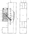
- Base body 1 with a U-shaped cross section and a space 3. On the left in the figure is on the top of the Base body 1 a fixed jaw 4 attached. Otherwise form the tops of the base body 1, a slideway 5 for a jaw 6 displaceable thereon. A cylinder space 7 for a piston 8 is formed in the jaw 6.
- the piston 8 has an underside running at an angle of approximately 45 ° Threaded hole 9 in which the threaded end of a threaded bolt 10 is screwed in, which extends through an area 3 in the area arranged opening 13 of the jaw 6 extends and at its free End has a bolt head 11 with a through hole 12.
- the Through bore 12 is aligned with a bore 14 of a series Bores in the base body 1 so that the threaded bolt 10 and thus the Piston 8 with the help of a through the holes 14 and the through hole 12 inserted locking bolt, not shown opposite the body can be locked.
- the piston 8 has an axial through bore 15 with one of the Fixed jaw 4 facing away from the terminal 16 arranged for a line carrying pressure medium. Otherwise, the piston 8 on the Fixed jaw 4 facing away from a spring 17 supported.
- the vice shown works as follows: First, the displaceable jaw 6 is brought into a position in which only a small clamping path is required for clamping the workpiece between the fixed jaw 4 and the displaceable jaw 6. There, the bolt head on the base body 1 is locked by inserting a locking bolt. If a pressure medium is now introduced into the cylinder space 7 via the connection 16 and the through bore 15, the piston 8 remains in place while the displaceable jaw 6 moves in the direction of the fixed jaw 4 and clamps the workpiece in the process.
- the displaceable jaw With increasing clamping force, the displaceable jaw is also pulled or pressed against the slideway 5 because the threaded bolt 10 acting as an anchor extends obliquely downward through the opening 13 of the jaw 6 at an angle of 45 ° to the slideway in the direction of the fixed jaw 4 , and because the piston 8 serving as an abutment is supported on the slideway 5 with the interposition of jaw parts. Setting up the end of the displaceable jaw 6 facing the fixed jaw 4 is thereby avoided.
- the base body 1 is in one piece formed and has a longitudinally extending T-shaped Slot 18 on. At the right end in FIG. 3, the base body is a cylinder 19 formed in which a piston 21 supported on a spring 20 is guided. Extends from the end face 22 of the base body or of the cylinder 19 a pressure medium inlet 23 to the working space 24 in the cylinder 19.
- the piston 21 is designed as an annular piston in which the end 25 one Threaded spindle 26 is sealed and guided. The end 25 of the Threaded spindle 26 extends beyond the end face 22 and points there a profile 27 for the approach of a tool.
- the threaded spindle 26 extends through the T-shaped groove 18.
- an adjusting block 28 designed as a threaded nut guided, the cross-sectional profile of the cross section of the T-shaped groove 18th is adjusted.
- One in the movable jaw 6 as well as in the adjustment block 28 with bolt 29 articulated bracket 30 connects the adjusting block 28 with the jaw 6.
- the vice shown in Figures 3 and 4 works as follows: By turning the threaded spindle 26, the displaceable jaw 6 is in a Position brought, in which only a small span to clamp the Workpiece between the fixed jaw and the movable jaw required is. Is now the working space 24 in the Cylinder 19 is pressurized, then the piston 21 moves with the threaded spindle 26, the adjusting block 28 and the jaw 6 in the direction of the Fixed jaw 4, whereby the workpiece is clamped. With increasing The displaceable jaw 6 is also pulled against the slideway 5. Setting up the end of the movable jaw facing the fixed jaw Cheek 6 is avoided.
Landscapes
- Engineering & Computer Science (AREA)
- Mechanical Engineering (AREA)
- Gripping Jigs, Holding Jigs, And Positioning Jigs (AREA)
- Clamps And Clips (AREA)
Applications Claiming Priority (2)
| Application Number | Priority Date | Filing Date | Title |
|---|---|---|---|
| DE1997145895 DE19745895C1 (de) | 1997-10-17 | 1997-10-17 | Spannstock |
| DE19745895 | 1997-10-17 |
Publications (2)
| Publication Number | Publication Date |
|---|---|
| EP0909613A2 true EP0909613A2 (fr) | 1999-04-21 |
| EP0909613A3 EP0909613A3 (fr) | 2001-10-31 |
Family
ID=7845821
Family Applications (1)
| Application Number | Title | Priority Date | Filing Date |
|---|---|---|---|
| EP98116462A Withdrawn EP0909613A3 (fr) | 1997-10-17 | 1998-08-31 | Etau |
Country Status (2)
| Country | Link |
|---|---|
| EP (1) | EP0909613A3 (fr) |
| DE (1) | DE19745895C1 (fr) |
Cited By (1)
| Publication number | Priority date | Publication date | Assignee | Title |
|---|---|---|---|---|
| GB2399818A (en) * | 2003-02-21 | 2004-09-29 | Thomas Ryan | Acetylation of a lignocellulosic material |
Family Cites Families (6)
| Publication number | Priority date | Publication date | Assignee | Title |
|---|---|---|---|---|
| DE2647832C3 (de) * | 1976-10-22 | 1979-04-12 | Willy 7464 Schoemberg Klingen | Druckmittelbetätigtes Spannwerkzeug mit manuell zustellbarem Spannblock |
| AR221544A1 (es) * | 1980-06-19 | 1981-02-13 | Anastasia Julio C | Morsa hidraulica semiautomatica |
| FR2559085B2 (fr) * | 1984-02-02 | 1987-06-26 | Boucher Freres Sarl Ets | Dispositif permettant de maintenir une piece a usiner dans une position determinee par rapport a une machine-outil sur laquelle ce dispositif peut etre fixe |
| DE8714423U1 (de) * | 1987-10-29 | 1989-02-23 | Otavi Minen AG, 6236 Eschborn | Mehrschaliger Schornstein |
| DE8715423U1 (de) * | 1987-11-21 | 1988-02-11 | Rückher, Jürgen, 7539 Kämpfelbach | Vorrichtung zum Spannen von Werkstücken, insbesondere Präzisionsschraubstock |
| DE4119026A1 (de) * | 1991-06-10 | 1992-12-17 | Linhardt Hans Peter | Spannvorrichtung fuer zu verleimende und anderweitig zu bearbeitende bauteile |
-
1997
- 1997-10-17 DE DE1997145895 patent/DE19745895C1/de not_active Expired - Fee Related
-
1998
- 1998-08-31 EP EP98116462A patent/EP0909613A3/fr not_active Withdrawn
Cited By (1)
| Publication number | Priority date | Publication date | Assignee | Title |
|---|---|---|---|---|
| GB2399818A (en) * | 2003-02-21 | 2004-09-29 | Thomas Ryan | Acetylation of a lignocellulosic material |
Also Published As
| Publication number | Publication date |
|---|---|
| EP0909613A3 (fr) | 2001-10-31 |
| DE19745895C1 (de) | 1999-02-18 |
Similar Documents
| Publication | Publication Date | Title |
|---|---|---|
| EP0623065B1 (fr) | Machoire profilee de serrage et procede de serrage de pieces | |
| EP0910497A1 (fr) | Serre-joints | |
| DD240859A5 (de) | Maschinenschraubstock | |
| WO2019158590A1 (fr) | Dispositif tendeur | |
| DE102020102910B3 (de) | Schraubzwinge | |
| EP1180603B1 (fr) | Elément support | |
| EP0854771B1 (fr) | Machoire de serrage profilee pour dispositif de serrage | |
| DE3329942C1 (de) | Spannvorrichtung für insbes. spanabhebend zu bearbeitende Werkstücke | |
| DE4133537A1 (de) | Spannvorrichtung fuer insbesondere spanabnehmend zu bearbeitende werkstuecke | |
| EP0909613A2 (fr) | Etau | |
| EP0258483A1 (fr) | Dispositif de serrage pour pièces de travail | |
| DE20303039U1 (de) | Kraftspannvorrichtung | |
| DE1502860A1 (de) | Werkzeugmaschine mit einer Einspannvorrichtung fuer das Werkstueck | |
| DE202012002940U1 (de) | Spannvorrichtung | |
| DE4341744C2 (de) | Tiefziehspanner für Spannvorrichtungen an Werkstückbearbeitungsmaschinen | |
| CH657802A5 (de) | Vorrichtung zur lagefixierung von werkstuecktraegern auf werkzeugmaschinen. | |
| DE3531507C2 (fr) | ||
| EP4190492A1 (fr) | Système d'adaptateur d'établi pour établis pourvus de grille perforée | |
| DE3925956C1 (en) | Bench clamp for workpiece fixture - has multi-arm swivelling jaws activated by lever attached to body | |
| DE2359131A1 (de) | Vorrichtung zum verbinden der raender von kordabschnitten | |
| DE3538972C1 (de) | Spannvorrichtung für insbes. spanabhebend zu bearbeitende Werkstücke | |
| DE2149628C3 (de) | Schraubstock mit einer feststehenden Schraubstockbacke und einer die bewegliche Schraubstockbacke tragenden Führungsschiene | |
| CH383727A (de) | Werkzeug zum Festhalten von Werkstücken, insbesondere bei Metallbearbeitungs-Werkzeugmaschinen | |
| DE8702023U1 (de) | Hydraulisches Spannelement | |
| DE10053668C1 (de) | Spannvorrichtung |
Legal Events
| Date | Code | Title | Description |
|---|---|---|---|
| PUAI | Public reference made under article 153(3) epc to a published international application that has entered the european phase |
Free format text: ORIGINAL CODE: 0009012 |
|
| AK | Designated contracting states |
Kind code of ref document: A2 Designated state(s): AT BE CH CY DE DK ES FI FR GB GR IE IT LI LU MC NL PT SE |
|
| AX | Request for extension of the european patent |
Free format text: AL;LT;LV;MK;RO;SI |
|
| PUAL | Search report despatched |
Free format text: ORIGINAL CODE: 0009013 |
|
| AK | Designated contracting states |
Kind code of ref document: A3 Designated state(s): AT BE CH CY DE DK ES FI FR GB GR IE IT LI LU MC NL PT SE |
|
| AX | Request for extension of the european patent |
Free format text: AL;LT;LV;MK;RO;SI |
|
| AKX | Designation fees paid | ||
| REG | Reference to a national code |
Ref country code: DE Ref legal event code: 8566 |
|
| STAA | Information on the status of an ep patent application or granted ep patent |
Free format text: STATUS: THE APPLICATION IS DEEMED TO BE WITHDRAWN |
|
| 18D | Application deemed to be withdrawn |
Effective date: 20020502 |