EP0909613A2 - Vice - Google Patents
Vice Download PDFInfo
- Publication number
- EP0909613A2 EP0909613A2 EP98116462A EP98116462A EP0909613A2 EP 0909613 A2 EP0909613 A2 EP 0909613A2 EP 98116462 A EP98116462 A EP 98116462A EP 98116462 A EP98116462 A EP 98116462A EP 0909613 A2 EP0909613 A2 EP 0909613A2
- Authority
- EP
- European Patent Office
- Prior art keywords
- jaw
- piston
- base body
- slideway
- fixed jaw
- Prior art date
- Legal status (The legal status is an assumption and is not a legal conclusion. Google has not performed a legal analysis and makes no representation as to the accuracy of the status listed.)
- Withdrawn
Links
Images

Classifications
-
- B—PERFORMING OPERATIONS; TRANSPORTING
- B25—HAND TOOLS; PORTABLE POWER-DRIVEN TOOLS; MANIPULATORS
- B25B—TOOLS OR BENCH DEVICES NOT OTHERWISE PROVIDED FOR, FOR FASTENING, CONNECTING, DISENGAGING OR HOLDING
- B25B5/00—Clamps
- B25B5/06—Arrangements for positively actuating jaws
- B25B5/061—Arrangements for positively actuating jaws with fluid drive
-
- B—PERFORMING OPERATIONS; TRANSPORTING
- B25—HAND TOOLS; PORTABLE POWER-DRIVEN TOOLS; MANIPULATORS
- B25B—TOOLS OR BENCH DEVICES NOT OTHERWISE PROVIDED FOR, FOR FASTENING, CONNECTING, DISENGAGING OR HOLDING
- B25B1/00—Vices
- B25B1/06—Arrangements for positively actuating jaws
- B25B1/10—Arrangements for positively actuating jaws using screws
- B25B1/12—Arrangements for positively actuating jaws using screws with provision for disengagement
-
- B—PERFORMING OPERATIONS; TRANSPORTING
- B25—HAND TOOLS; PORTABLE POWER-DRIVEN TOOLS; MANIPULATORS
- B25B—TOOLS OR BENCH DEVICES NOT OTHERWISE PROVIDED FOR, FOR FASTENING, CONNECTING, DISENGAGING OR HOLDING
- B25B1/00—Vices
- B25B1/06—Arrangements for positively actuating jaws
- B25B1/18—Arrangements for positively actuating jaws motor driven, e.g. with fluid drive, with or without provision for manual actuation
Definitions
- the invention relates to a vice with a body, with a Base body arranged fixed jaw, one on a slideway of the base body movable against the fixed jaw and with a relative to the Jaw movable abutment that has an anchor attached to its free end has an opening for a locking bolt which in one of a series of holes in the base body can be inserted.
- the base body has lateral guide rails that by associated guide elements of the sliding jaw so that the sliding jaw does not lift off the slide, if the tension acts between it and the abutment.
- that Workpiece to be machined usually in the area of the tops of Fixed jaw and movable jaw is clamped on the sliding jaw a set-up moment. The size of the installation moment depends on the size of the clamping force.
- the object of the invention is a vice of the type described To improve the genus in such a way that the sliding jaw no longer rises.
- a device for generating a clamping force between the displaceable The jaw and the abutment can in principle be of any design.
- a preferred embodiment of the invention is characterized in that in the movable jaw a cylinder space for one that forms the abutment Piston is arranged on which the armature is attached.
- the anchor is According to the invention a threaded bolt which with its threaded end in a Threaded bore of the piston is screwed in.
- the anchor can also open otherwise attached or stored on the piston.
- the end facing away from the fixed jaw with a connection for one line carrying pressure medium is equipped.
- the pressure medium connection is then at a sufficiently safe distance from the location of the Workpiece processing and can also be protected within if necessary the cheek be arranged.
- the piston should be on its the Fixed jaw facing away from the end face on a spring so that the sliding jaw not only the workpiece when the pressure is released releases, but also moves back to a defined rest position.
- the object on which the invention is based can, as it were, by Kinematic reversals can also be solved using a vice that is marked is by a base body, by one arranged on the base body Fixed jaw, against by on a slideway of the base body the fixed jaw slidable jaw, which has an anchor that is at an angle to the slideway downwards towards the Fixed jaw extends and engages a piston at its free end, which in a cylinder arranged on the base body is guided.
- the piston is guided parallel to the direction of displacement of the movable jaw be. It can also be supported on a spring so that it can Pressure relief moved back to a defined rest position.
- the cheek is longitudinally adjustable on one connected to the piston Component attacks.
- this is in the piston a threaded spindle is mounted, which extends along the base body and on which a threaded nut designed as an adjusting block is guided, the anchor is attacking.
- the anchor is preferably one on both sides articulated bracket.
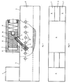
- Base body 1 with a U-shaped cross section and a space 3. On the left in the figure is on the top of the Base body 1 a fixed jaw 4 attached. Otherwise form the tops of the base body 1, a slideway 5 for a jaw 6 displaceable thereon. A cylinder space 7 for a piston 8 is formed in the jaw 6.
- the piston 8 has an underside running at an angle of approximately 45 ° Threaded hole 9 in which the threaded end of a threaded bolt 10 is screwed in, which extends through an area 3 in the area arranged opening 13 of the jaw 6 extends and at its free End has a bolt head 11 with a through hole 12.
- the Through bore 12 is aligned with a bore 14 of a series Bores in the base body 1 so that the threaded bolt 10 and thus the Piston 8 with the help of a through the holes 14 and the through hole 12 inserted locking bolt, not shown opposite the body can be locked.
- the piston 8 has an axial through bore 15 with one of the Fixed jaw 4 facing away from the terminal 16 arranged for a line carrying pressure medium. Otherwise, the piston 8 on the Fixed jaw 4 facing away from a spring 17 supported.
- the vice shown works as follows: First, the displaceable jaw 6 is brought into a position in which only a small clamping path is required for clamping the workpiece between the fixed jaw 4 and the displaceable jaw 6. There, the bolt head on the base body 1 is locked by inserting a locking bolt. If a pressure medium is now introduced into the cylinder space 7 via the connection 16 and the through bore 15, the piston 8 remains in place while the displaceable jaw 6 moves in the direction of the fixed jaw 4 and clamps the workpiece in the process.
- the displaceable jaw With increasing clamping force, the displaceable jaw is also pulled or pressed against the slideway 5 because the threaded bolt 10 acting as an anchor extends obliquely downward through the opening 13 of the jaw 6 at an angle of 45 ° to the slideway in the direction of the fixed jaw 4 , and because the piston 8 serving as an abutment is supported on the slideway 5 with the interposition of jaw parts. Setting up the end of the displaceable jaw 6 facing the fixed jaw 4 is thereby avoided.
- the base body 1 is in one piece formed and has a longitudinally extending T-shaped Slot 18 on. At the right end in FIG. 3, the base body is a cylinder 19 formed in which a piston 21 supported on a spring 20 is guided. Extends from the end face 22 of the base body or of the cylinder 19 a pressure medium inlet 23 to the working space 24 in the cylinder 19.
- the piston 21 is designed as an annular piston in which the end 25 one Threaded spindle 26 is sealed and guided. The end 25 of the Threaded spindle 26 extends beyond the end face 22 and points there a profile 27 for the approach of a tool.
- the threaded spindle 26 extends through the T-shaped groove 18.
- an adjusting block 28 designed as a threaded nut guided, the cross-sectional profile of the cross section of the T-shaped groove 18th is adjusted.
- One in the movable jaw 6 as well as in the adjustment block 28 with bolt 29 articulated bracket 30 connects the adjusting block 28 with the jaw 6.
- the vice shown in Figures 3 and 4 works as follows: By turning the threaded spindle 26, the displaceable jaw 6 is in a Position brought, in which only a small span to clamp the Workpiece between the fixed jaw and the movable jaw required is. Is now the working space 24 in the Cylinder 19 is pressurized, then the piston 21 moves with the threaded spindle 26, the adjusting block 28 and the jaw 6 in the direction of the Fixed jaw 4, whereby the workpiece is clamped. With increasing The displaceable jaw 6 is also pulled against the slideway 5. Setting up the end of the movable jaw facing the fixed jaw Cheek 6 is avoided.
Abstract
Description
Die Erfindung betrifft einen Spannstock mit einem Grundkörper, mit einer am Grundkörper angeordneten Festbacke, einer auf einer Gleitbahn des Grundkörpers gegen die Festbacke verschiebbaren Backe und mit einem relativ zur Backe beweglichen Widerlager, das einen Anker aufweist, der an seinem freien Ende eine Öffnung für einen Verriegelungsbolzen aufweist, der in eines einer Reihe von Löchern des Grundkörpers einführbar ist.The invention relates to a vice with a body, with a Base body arranged fixed jaw, one on a slideway of the base body movable against the fixed jaw and with a relative to the Jaw movable abutment that has an anchor attached to its free end has an opening for a locking bolt which in one of a series of holes in the base body can be inserted.
Spannstöcke sind in verschiedenen Ausführungen bekannt. Sie werden unter anderem in Werkzeugmaschinen eingesetzt, um das zu bearbeitende Werkstück zwischen der Festbacke und der verschiebbaren Backe einzuspannen. Bei einer aus der Praxis bekannten Ausführung der eingangs beschriebenen Gattung weist der Grundkörper seitliche Führungsschienen auf, die von zugeordneten Führungselementen der verschiebbaren Backe unterfaßt werden, so daß die verschiebbare Backe nicht von der Gleitbahn abhebt, wenn zwischen ihr und dem Widerlager die Spannkraft wirkt. Da jedoch das zu bearbeitende Werkstück in der Regel im Bereich der Oberseiten von Festbacke und verschiebbarer Backe eingespannt wird, wirkt an der verschiebbaren Backe ein Aufstellmoment. Die Größe des Aufstellmomentes ist abhängig von der Größe der Spannkraft. Da die Führung zwischen dem Grundkörper und der verschiebbaren Backe notwendigerweise ein wenn auch nur geringes Spiel aufweisen muß, stellt sich das der Festbacke zugewandte Ende der verschiebbaren Backe unter der Wirkung der Spannkräfte mehr oder weniger auf, wobei ein Teil der Aufstellbewegung auch aus der Verformung der Bauteile resultieren kann.Vices are known in various designs. You will be under other used in machine tools to the workpiece to be machined clamp between the fixed jaw and the movable jaw. In a known from practice version of the above Genus, the base body has lateral guide rails that by associated guide elements of the sliding jaw so that the sliding jaw does not lift off the slide, if the tension acts between it and the abutment. However, since that Workpiece to be machined usually in the area of the tops of Fixed jaw and movable jaw is clamped on the sliding jaw a set-up moment. The size of the installation moment depends on the size of the clamping force. Because the leadership between the Base body and the sliding jaw necessarily an if even if there is only slight play, the fixed jaw turns facing end of the sliding jaw under the action of the Clamping forces more or less, with part of the installation movement can also result from the deformation of the components.
Aufgabe der Erfindung ist es, einen Spannstock der eingangs beschriebenen Gattung so zu verbessern, daß die verschiebbare Backe sich nicht mehr aufstellt.The object of the invention is a vice of the type described To improve the genus in such a way that the sliding jaw no longer rises.
Diese Aufgabe wird dadurch gelöst, daß das Widerlager unter Zwischenschaltung von Bodenteilen auf der Gleitbahn abgestützt ist und daß der Anker sich durch eine Öffnung der Backe unter einem Winkel zur Gleitbahn schräg nach unten in Richtung auf die Festbacke erstreckt. - Eine zwischen der verschiebbaren Backe und dem Widerlager erzeugte Spannkraft hat nunmehr nicht nur eine Komponente in Richtung auf die Festbacke, sondern auch eine Komponente senkrecht zur Gleitbahn, welche die verschiebbare Backe an der Gleitbahn hält bzw. gegen die Gleitbahn drückt, weil das Widerlager unter Zwischenschaltung von Backenteilen auf der Gleitbahn abgestützt ist. Diese senkrecht zur Gleitbahn wirkende Kraft nimmt mit zunehmender Spannkraft zu, und zwar nach Maßgabe des Winkels, unter dem der Anker zur Gleitbahn ausgerichtet ist. Ein Winkel von ca. 45° hat sich bewährt.This object is achieved in that the abutment under Interposition of floor parts is supported on the slide and that the anchor extends through an opening in the cheek at an angle to the Slideway extends obliquely downwards towards the fixed jaw. - One generated between the movable jaw and the abutment Tension now has not only one component in the direction of the Fixed jaw, but also a component perpendicular to the slideway, which the sliding jaw holds against the slideway or against the slideway presses because the abutment with the interposition of jaw parts the slideway is supported. This force acting perpendicular to the slideway increases with increasing tension, according to the Angle at which the anchor is aligned with the slideway. An angle of approx. 45 ° has proven itself.
Eine Einrichtung zum Erzeugen einer Spannkraft zwischen der verschiebbaren Backe und dem Widerlager kann grundsätzlich beliebig ausgebildet sein. Eine bevorzugte Ausführung der Erfindung ist dadurch gekennzeichnet, daß in der verschiebbaren Backe ein Zylinderraum für einen das Widerlager bildenden Kolben angeordnet ist, an dem der Anker befestigt ist. Der Anker ist erfindungsgemäß ein Gewindebolzen, der mit seinem Gewindeende in eine Gewindebohrung des Kolbens eingedreht ist. Der Anker kann aber auch auf andere Weise am Kolben befestigt oder gelagert sein.A device for generating a clamping force between the displaceable The jaw and the abutment can in principle be of any design. A preferred embodiment of the invention is characterized in that in the movable jaw a cylinder space for one that forms the abutment Piston is arranged on which the armature is attached. The anchor is According to the invention a threaded bolt which with its threaded end in a Threaded bore of the piston is screwed in. The anchor can also open otherwise attached or stored on the piston.
Um auf einfache Weise die Zuführung eines Druckmittels zum Zylinderraum zu ermöglichen, kann der Kolben eine axiale Durchgangsbohrung aufweisen, die an ihrem der Festbacke abgewandten Ende mit einem Anschluß für eine druckmittelführende Leitung ausgerüstet ist. Der Druckmittelanschluß befindet sich dann in hinreichend sicherer Entfernung vom Ort der Werkstückbearbeitung und kann gegebenenfalls auch geschützt innerhalb der Backe angeordnet sein. Zweckmäßig sollte der Kolben auf seiner der Festbacke abgewandten Stirnseite auf einer Feder abgestützt sein, so daß bei Druckentlastung die verschiebbare Backe nicht nur das Werkstück freigibt, sondern sich auch in eine definierte Ruheposition zurückbewegt.To supply a pressure medium to the cylinder space in a simple manner to enable the piston to have an axial through bore, the end facing away from the fixed jaw with a connection for one line carrying pressure medium is equipped. The pressure medium connection is then at a sufficiently safe distance from the location of the Workpiece processing and can also be protected within if necessary the cheek be arranged. Appropriately, the piston should be on its the Fixed jaw facing away from the end face on a spring so that the sliding jaw not only the workpiece when the pressure is released releases, but also moves back to a defined rest position.
Die der Erfindung zugrundeliegende Aufgabe kann gleichsam im Wege der kinematischen Umkehr auch gelöst werden mit einem Spannstock, der gekennzeichnet ist durch einen Grundkörper, durch eine am Grundkörper angeordnete Festbacke, durch eine auf einer Gleitbahn des Grundkörpers gegen die Festbacke verschiebbaren Backe, die einen Anker aufweist, der sich unter einem Winkel zur Gleitbahn schräg nach unten in Richtung auf die Festbacke erstreckt und an dessen freiem Ende ein Kolben angreift, der in einem am Grundkörper angeordneten Zylinder geführt ist. Insbesondere soll der Kolben parallel zur Verschieberichtung der beweglichen Backe geführt sein. Er kann auch auf einer Feder abgestützt sein, damit er sich bei Druckentlastung in eine definierte Ruheposition zurückbewegt.The object on which the invention is based can, as it were, by Kinematic reversals can also be solved using a vice that is marked is by a base body, by one arranged on the base body Fixed jaw, against by on a slideway of the base body the fixed jaw slidable jaw, which has an anchor that is at an angle to the slideway downwards towards the Fixed jaw extends and engages a piston at its free end, which in a cylinder arranged on the base body is guided. In particular, should the piston is guided parallel to the direction of displacement of the movable jaw be. It can also be supported on a spring so that it can Pressure relief moved back to a defined rest position.
Damit die bewegliche Backe über größere Strecken längs der Gleitbahn verstellt werden kann, empfiehlt sich eine Ausführung, bei der der Anker in Verschieberichtung der Backe längs verstellbar an einem mit dem Kolben verbundenen Bauteil angreift. Bei einer bevorzugten Ausführung ist dazu im Kolben eine Gewindespindel gelagert, die sich längs des Grundkörpers erstreckt und auf der eine als Verstellkloben ausgebildete Gewindemutter geführt ist, an der der Anker angreift. Der Anker ist vorzugsweise eine beidseitig gelenkig gelagerte Lasche.So that the movable jaw can be adjusted over longer distances along the slideway a version in which the anchor is in the direction of displacement is recommended the cheek is longitudinally adjustable on one connected to the piston Component attacks. In a preferred embodiment, this is in the piston a threaded spindle is mounted, which extends along the base body and on which a threaded nut designed as an adjusting block is guided, the anchor is attacking. The anchor is preferably one on both sides articulated bracket.
Im folgenden wird ein in der Zeichnung dargestelltes Ausführungsbeispiel der Erfindung erläutert; es zeigen:
Figur 1- eine Seitenansicht, teilweise geschnitten, eines Spannstockes,
- Figur 2
- eine Draufsicht auf den Gegenstand nach
Figur 1, Figur 3- eine andere Ausführung des Gegenstandes nach
Figur 1, - Figur 4
- eine Stirnansicht des Gegenstandes nach
Figur 3.
- Figure 1
- a side view, partially in section, of a vice,
- Figure 2
- 2 shows a top view of the object according to FIG. 1,
- Figure 3
- another embodiment of the object according to Figure 1,
- Figure 4
- 3 shows an end view of the object according to FIG. 3.
Zu dem in der Zeichnung dargestellten Spannstock gehört ein
Grundkörper 1 mit einem U-förmigen Querschnitt und einem Zwischenraum
3. Auf der in der Figur linken Seite ist auf der Oberseite des
Grundkörpers 1 eine Festbacke 4 befestigt. Im übrigen bilden die Oberseiten
des Grundkörpers1 eine Gleitbahn 5 für eine darauf verschiebbare Backe 6.
In der Backe 6 ist ein Zylinderraum 7 für einen Kolben 8 ausgebildet. One belongs to the vice shown in the
Der Kolben 8 weist unterseitig eine unter einem Winkel von ca. 45° verlaufende
Gewindebohrung 9 auf, in die das Gewindeende eines Gewindebolzens
10 eingedreht ist, der sich durch eine im Bereich des Zwischenraums 3
angeordnete Öffnung 13 der Backe 6 erstreckt und der an seinem freien
Ende einen Bolzenkopf 11 mit einer Durchgangsbohrung 12 aufweist. Die
Durchgangsbohrung 12 fluchtet mit jeweils einer Bohrung 14 einer Reihe von
Bohrungen im Grundkörper 1, so daß der Gewindebolzen 10 und damit der
Kolben 8 mit Hilfe eines durch die Bohrungen 14 und die Durchgangsbohrung
12 gesteckten, nicht dargestellten Verriegelungsbolzens gegenüber
dem Grundkörper verriegelt werden kann.The
Der Kolben 8 weist eine axiale Durchgangsbohrung 15 mit einem an der der
Festbacke 4 abgewandten Ende angeordneten Anschluß 16 für eine
druckmittelführende Leitung auf. Im übrigen ist der Kolben 8 auf der der
Festbacke 4 abgewandten Seite auf einer Feder 17 abgestützt.The
Der dargestellte Spannstock funktioniert wie folgt:
Zunächst wird die verschiebbare Backe 6 in eine Position gebracht, bei der
nur ein geringer Spannweg zum Einspannen des Werkstückes zwischen der
Festbacke 4 und der verschiebbaren Backe 6 erforderlich ist. Dort wird der
Bolzenkopf am Grundkörper 1 durch Einführen eines Verriegelungsbolzens
verriegelt. Wird nunmehr über den Anschluß 16 und die Durchgangsbohrung
15 ein Druckmittel in den Zylinderraum 7 eingeführt, dann bleibt der
Kolben 8 an Ort und Stelle, während sich die verschiebbare Backe 6 in Richtung
auf die Festbacke 4 bewegt und dabei das Werkstück einspannt. Mit
zunehmender Spannkraft wird auch die verschiebbare Backe gegen die
Gleitbahn 5 gezogen bzw. gepreßt, weil der als Anker wirkende
Gewindebolzen 10 sich durch die Öffnung 13 der Backe 6 unter einem
Winkel von 45° zur Gleitbahn schräg nach unten in Richtung auf die
Festbacke 4 erstreckt, und weil der als Widerlager dienende Kolben 8 unter
Zwischenschaltung von Backenteilen auf der Gleitbahn 5 abgestützt ist. Ein
Aufstellen des der Festbacke 4 zugewandten Endes der verschiebbaren
Backe 6 wird dadurch vermieden. The vice shown works as follows:
First, the
Bei der in den Figuren 3 und 4 wiedergegebenen Ausführung bezeichnen
gleiche Bezugszeichen gleiche Teile. Der Grundkörper 1 ist einteilig
ausgebildet und weist eine sich in Längsrichtung erstreckende T-förmige
Nut 18 auf. Am in Figur 3 rechten Ende ist der Grundkörper als Zylinder 19
ausgebildet, in dem ein auf einer Feder 20 abgestützter Kolben 21 geführt ist.
Von der Stirnseite 22 des Grundkörpers bzw. des Zylinders 19 erstreckt sich
ein Druckmittelzulauf 23 zum Arbeitsraum 24 im Zylinder 19. Der Kolben 21
ist als ein Ringkolben ausgebildet, in dem das Ende 25 einer
Gewindespindel 26 abgedichtet gelagert und geführt ist. Das Ende 25 der
Gewindespindel 26 erstreckt sich über die Stirnseite 22 hinaus und weist dort
ein Profil 27 für den Ansatz eines Werkzeuges auf.Designate in the embodiment shown in Figures 3 and 4
same reference numerals same parts. The
Die Gewindespindel 26 erstreckt sich durch die T-förmige Nut 18. Auf der
Gewindespindel 26 ist ein als Gewindemutter ausgebildeter Verstellkloben 28
geführt, dessen Querschnittsprofil dem Querschnitt der T-förmigen Nut 18
angepaßt ist. Eine sowohl in der beweglichen Backe 6 als auch im Verstellkloben
28 mit Bolzen 29 gelenkig gelagerte Lasche 30 verbindet den Verstellkloben
28 mit der Backe 6.The threaded
Der in den Figuren 3 und 4 dargestellte Spannstock funktioniert wie folgt:
Durch Drehen der Gewindespindel 26 wird die verschiebbare Backe 6 in eine
Position gebracht, bei der nur ein geringer Spannweg zum Einspannen des
Werkstücks zwischen der Festbacke und der verschiebbaren Backe erforderlich
ist. Wird nunmehr über den Druckmittelzulauf 23 der Arbeitsraum 24 im
Zylinder 19 unter Druck gesetzt, dann bewegt sich der Kolben 21 mit der Gewindespindel
26, dem Verstellkloben 28 und der Backe 6 in Richtung auf die
Festbacke 4, wodurch das Werkstück eingespannt wird. Mit zunehmender
Spannkraft wird auch die verschiebbare Backe 6 gegen die Gleitbahn 5 gezogen.
Ein Aufstellen des der Festbacke 4 zugewandten Endes der verschiebbaren
Backe 6 wird dadurch vermieden.The vice shown in Figures 3 and 4 works as follows:
By turning the threaded
Claims (11)
Applications Claiming Priority (2)
| Application Number | Priority Date | Filing Date | Title |
|---|---|---|---|
| DE19745895 | 1997-10-17 | ||
| DE1997145895 DE19745895C1 (en) | 1997-10-17 | 1997-10-17 | Work clamp rod for machine tools |
Publications (2)
| Publication Number | Publication Date |
|---|---|
| EP0909613A2 true EP0909613A2 (en) | 1999-04-21 |
| EP0909613A3 EP0909613A3 (en) | 2001-10-31 |
Family
ID=7845821
Family Applications (1)
| Application Number | Title | Priority Date | Filing Date |
|---|---|---|---|
| EP98116462A Withdrawn EP0909613A3 (en) | 1997-10-17 | 1998-08-31 | Vice |
Country Status (2)
| Country | Link |
|---|---|
| EP (1) | EP0909613A3 (en) |
| DE (1) | DE19745895C1 (en) |
Cited By (1)
| Publication number | Priority date | Publication date | Assignee | Title |
|---|---|---|---|---|
| GB2399818A (en) * | 2003-02-21 | 2004-09-29 | Thomas Ryan | Acetylation of a lignocellulosic material |
Citations (4)
| Publication number | Priority date | Publication date | Assignee | Title |
|---|---|---|---|---|
| DE2647832A1 (en) * | 1976-10-22 | 1978-04-27 | Willy Klingen | Pressure medium operated clamping tool - has manually adjustable clamping block and hydraulically actuated tool clamping action |
| FR2484892A1 (en) * | 1980-06-19 | 1981-12-24 | Anastasia Julio | Semi-automatic machine vice - uses screw and hydraulic ram for coarse and fine jaw movement with ram=chamber in fixed jaw locating end of piston |
| FR2559085A2 (en) * | 1984-02-02 | 1985-08-09 | Boucher Freres Sarl Ets | Device allowing a workpiece to be machined to be held in a predetermined position with respect to a machine tool upon which this device may be fixed |
| DE8715423U1 (en) * | 1987-11-21 | 1988-02-11 | Rueckher, Juergen, 7539 Kaempfelbach, De |
Family Cites Families (2)
| Publication number | Priority date | Publication date | Assignee | Title |
|---|---|---|---|---|
| DE8714423U1 (en) * | 1987-10-29 | 1989-02-23 | Otavi Minen Ag, 6236 Eschborn, De | |
| DE4119026A1 (en) * | 1991-06-10 | 1992-12-17 | Linhardt Hans Peter | Pneumatically actuated cramp for holding glued joints - has movable jaw actuated by air cylinder and mounted on bracket which can be adjusted along bar |
-
1997
- 1997-10-17 DE DE1997145895 patent/DE19745895C1/en not_active Expired - Fee Related
-
1998
- 1998-08-31 EP EP98116462A patent/EP0909613A3/en not_active Withdrawn
Patent Citations (4)
| Publication number | Priority date | Publication date | Assignee | Title |
|---|---|---|---|---|
| DE2647832A1 (en) * | 1976-10-22 | 1978-04-27 | Willy Klingen | Pressure medium operated clamping tool - has manually adjustable clamping block and hydraulically actuated tool clamping action |
| FR2484892A1 (en) * | 1980-06-19 | 1981-12-24 | Anastasia Julio | Semi-automatic machine vice - uses screw and hydraulic ram for coarse and fine jaw movement with ram=chamber in fixed jaw locating end of piston |
| FR2559085A2 (en) * | 1984-02-02 | 1985-08-09 | Boucher Freres Sarl Ets | Device allowing a workpiece to be machined to be held in a predetermined position with respect to a machine tool upon which this device may be fixed |
| DE8715423U1 (en) * | 1987-11-21 | 1988-02-11 | Rueckher, Juergen, 7539 Kaempfelbach, De |
Cited By (1)
| Publication number | Priority date | Publication date | Assignee | Title |
|---|---|---|---|---|
| GB2399818A (en) * | 2003-02-21 | 2004-09-29 | Thomas Ryan | Acetylation of a lignocellulosic material |
Also Published As
| Publication number | Publication date |
|---|---|
| DE19745895C1 (en) | 1999-02-18 |
| EP0909613A3 (en) | 2001-10-31 |
Similar Documents
| Publication | Publication Date | Title |
|---|---|---|
| EP0910497A1 (en) | Screw clamp | |
| DE10118664B4 (en) | Clamping device for workpieces to be machined with imbalance compensation | |
| DD240859A5 (en) | MACHINE VICE | |
| EP1180603B1 (en) | Support member | |
| EP0854771B1 (en) | Shaped clamping jaw for a clamping device | |
| DE3329942C1 (en) | Clamping device in particular for workpieces to be machined | |
| EP0909613A2 (en) | Vice | |
| DE4133537A1 (en) | Workpiece clamping fixture for machining operations - has rollers in inclined guideways interposed between clamping jaws and carrier block to force work down onto base | |
| DE2065506B2 (en) | HYDRAULIC POWER CYLINDER | |
| DE102020102910B3 (en) | Screw clamp | |
| EP0258483A1 (en) | Clamping device for work pieces | |
| DE1502860A1 (en) | Machine tool with a clamping device for the workpiece | |
| DE2530776A1 (en) | Portable vice with G-clamp for mounting - having orientation by shafts received in square array of holes | |
| DE4341744C2 (en) | Deep drawing clamps for clamping devices on workpiece processing machines | |
| DE3531507C2 (en) | ||
| CH657802A5 (en) | DEVICE FOR FIXING THE POSITION OF WORKPIECE CARRIERS ON MACHINE TOOLS. | |
| WO2019158590A1 (en) | Bracing apparatus | |
| DE202012002940U1 (en) | jig | |
| DE2359131A1 (en) | Edge jointing of rubber-embedded tyre cord - using two pairs of jaws sliding in vee slots in seatings | |
| DE2149628C3 (en) | Vice with a fixed vice jaw and a guide rail supporting the movable vice jaw | |
| DE10053668C1 (en) | Clamp for clamping objects against fixed surface consists of two wedge units movable along slide surfaces, screw in hole, with nut enabling wedge units to slide and form parallelepiped divided along diagonal surface | |
| EP1655104B1 (en) | Clamping device for clamping pieces | |
| EP0588997B1 (en) | Multiple workpiece holding fixture | |
| CH383727A (en) | Tool for holding workpieces, in particular in metalworking machine tools | |
| DE2620658B1 (en) | Workpiece angular clamping mechanism - has two vices each with pair of jaws relatively adjustable to each other perpendicular to mating faces |
Legal Events
| Date | Code | Title | Description |
|---|---|---|---|
| PUAI | Public reference made under article 153(3) epc to a published international application that has entered the european phase |
Free format text: ORIGINAL CODE: 0009012 |
|
| AK | Designated contracting states |
Kind code of ref document: A2 Designated state(s): AT BE CH CY DE DK ES FI FR GB GR IE IT LI LU MC NL PT SE |
|
| AX | Request for extension of the european patent |
Free format text: AL;LT;LV;MK;RO;SI |
|
| PUAL | Search report despatched |
Free format text: ORIGINAL CODE: 0009013 |
|
| AK | Designated contracting states |
Kind code of ref document: A3 Designated state(s): AT BE CH CY DE DK ES FI FR GB GR IE IT LI LU MC NL PT SE |
|
| AX | Request for extension of the european patent |
Free format text: AL;LT;LV;MK;RO;SI |
|
| AKX | Designation fees paid | ||
| REG | Reference to a national code |
Ref country code: DE Ref legal event code: 8566 |
|
| STAA | Information on the status of an ep patent application or granted ep patent |
Free format text: STATUS: THE APPLICATION IS DEEMED TO BE WITHDRAWN |
|
| 18D | Application deemed to be withdrawn |
Effective date: 20020502 |