EP0909114B1 - Verfahren und Vorrichtung zur Anzeige von Lautschprecherstörungen - Google Patents
Verfahren und Vorrichtung zur Anzeige von Lautschprecherstörungen Download PDFInfo
- Publication number
- EP0909114B1 EP0909114B1 EP98203060A EP98203060A EP0909114B1 EP 0909114 B1 EP0909114 B1 EP 0909114B1 EP 98203060 A EP98203060 A EP 98203060A EP 98203060 A EP98203060 A EP 98203060A EP 0909114 B1 EP0909114 B1 EP 0909114B1
- Authority
- EP
- European Patent Office
- Prior art keywords
- fault
- speakers
- radio
- distortion
- speaker
- Prior art date
- Legal status (The legal status is an assumption and is not a legal conclusion. Google has not performed a legal analysis and makes no representation as to the accuracy of the status listed.)
- Expired - Lifetime
Links
Images


Classifications
-
- H—ELECTRICITY
- H04—ELECTRIC COMMUNICATION TECHNIQUE
- H04R—LOUDSPEAKERS, MICROPHONES, GRAMOPHONE PICK-UPS OR LIKE ACOUSTIC ELECTROMECHANICAL TRANSDUCERS; ELECTRIC HEARING AIDS; PUBLIC ADDRESS SYSTEMS
- H04R29/00—Monitoring arrangements; Testing arrangements
- H04R29/001—Monitoring arrangements; Testing arrangements for loudspeakers
- H04R29/003—Monitoring arrangements; Testing arrangements for loudspeakers of the moving-coil type
Definitions
- This invention relates to the indication of speaker faults to a vehicle operator or to service personnel.
- US 5631566 discloses a radio speaker short circuit detection system.
- US 5453716 discloses a clip detection system for limiting an audio output signal to avoid clipping.
- EP 0607693 discloses a method of using clipping detection to diagnose speaker faults.
- a vehicle radio as claimed in claim 1 and a method of indicating speaker faults as claimed in claim 9.
- an audio amplifier with the capability to detect a speaker fault is configured to produce a signal when a fault occurs.
- a microprocessor responsive to such a fault signal sends a suitable message to the radio display to apprise the operator of the condition.
- the fault information is stored in memory associated with the microprocessor and is retrieved via a data bus by a diagnostic tool used by a service technician.
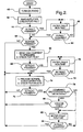
- Fault detection begins when a radio is turned on. Then before an audio signal is applied, the amplifier is biased and a fault check is performed by the amplifier. At this stage, the fault detection feature can respond to a short to power or to ground and to an open load. If a fault is found the microprocessor executes a fault routine which effects an indication and/or stores fault data and limits the output of the radio from playing until the fault is repaired or otherwise cleared. If there is no fault or if a fault has been cleared, the operator may test for a shorted load by pressing designated radio buttons which cause a high current audio signal to be sent to the speakers. If a fault is detected then, the fault routine is entered but this time the radio is permitted to play at a reduced volume as long as the fault is present. Finally, if no fault is present, normal audio operation is provided and fault detection continues.
- an automotive radio that term is used herein to include an audio source which may be, for example, a cassette player or other source as well as a tuner.
- a radio includes an audio source 10 providing a signal to an audio amplifier 12 which, in this example, has four output channels, each supplying at least one speaker 14.
- the amplifier is of the type which has built-in circuits 16 for detecting speaker faults in each channel and includes means for disabling any channel exhibiting a fault.
- the amplifier 12 also includes a distortion detection circuit 18 which is coupled to an output line 20 to impose a signal on the line when distortion is present.
- the amplifier is well known for use in automotive radios where the speaker fault and protection capability is desired. It is available from SGS Thomson Microelectronics, of Milan, Italy, as a bridge audio amplifier part no. QBA TDA7385. Similar devices serving only one or two channels are also available from the same source.
- a microprocessor 22 is coupled to the line 20 to monitor its state and to discriminate between distortion and speaker fault signals.
- the microprocessor is connected to a serial data bus 24 to supply a fault signal or stored fault data to a normal dealership diagnostic tool 26 which is not part of the radio but is an instrument to be applied by a service technician.
- the radio has a display 28 which is coupled to the microprocessor 22 to display a speaker fault message as well as station identification and other information.
- the fault message may be, for example, "SPKR PRB", or an error code such as "ERR3".
- Buttons 30 or other normal radio controls provide inputs to the microprocessor 22.
- the method of detecting and indicating speaker faults is illustrated by the flow charts of Figures 2 and 3 wherein the functional description of each block in the charts is accompanied by a number in angle brackets ⁇ nn> which corresponds to the reference number of the block.
- the method involves manual inputs, operation by the amplifier 12 and the fault circuits 16, and operations performed by the microprocessor 22.
- a DC bias is applied to each channel of the amplifier and the fault circuits 16 check for faults ⁇ 42>.
- no audio signal is applied and faults due to open load, shorts to ground or shorts to power will be revealed.
- a fault circuit changes the state of line 20 and a fault routine is entered ⁇ 46>.
- the fault routine ⁇ 46> is detailed in Figure 3 .
- the microprocessor responds to the state of line 20 by setting a fault flag and indicating a fault ⁇ 48 > by sending a message to the radio display and storing the fault flag for future examination by the diagnostic tool 26. If the radio is turned off while the fault routine is being executed ⁇ 50 > the fault detection will end ⁇ 52 >. If the radio remains on, a limited audio performance may be allowed ⁇ 54 > but it is preferred to keep the sound off during this initial fault test; however for later tests the limited audio (low volume) is permitted. Next another fault check is made ⁇ 56> so that if the fault remains ⁇ 58> the fault routine continues until the radio is turned off. Whenever the fault is cleared either due to a repair or due to an intermittent condition, the fault flag is reset, the fault indication is removed, and a fault occurred flag and fault information will be stored ⁇ 60>.
- the fault circuits 16 of the amplifier are able to identify for each channel the specific type of fault; however there is no convenient way to extract that information for diagnostic purposes.
- the amplifier may be modified to include communication capability to output the detailed fault information.
- a modified amplifier 12' includes a data storage register 90, and a clock bus 92 and a data bus 94 connect the register to the microprocessor 22.
- the fault circuits 16 for the several amplifiers channels each have four outputs for coupling specific fault data to preassigned bits D0 to D15 of the register 90.
- the fault outputs are short to B+ (power), short to ground, shorted load and open load.
- the register data is clocked onto the data bus and read by the microprocessor to determine specific fault information and to provide appropriate indication. This data is independent of the distortion signal, although this communication capability can include distortion data if desired.
- the method of Figures 2 and 3 remains the same except that the high current used in step ⁇ 66> does not have to be limited to a non-distorting level, and the steps ⁇ 78> and ⁇ 80> are omitted. Since more specific fault information is available, specific diagnosis may be accomplished by the diagnostic tool 26 as it accesses the information. Depending on the extent of the radio display 28, specific information may be shown there as well.
- the detection of speaker faults simplifies the diagnosis of radio problems and if there is a speaker fault, avoids the time and expense of unnecessary removal and testing of radios, which is usually the first step in analyzing such problems.
- the modified amplifier when used, the problem is narrowed to a particular fault in a specific channel, thereby greatly facilitating repair.
- customer satisfaction is improved by detecting and repairing speaker faults in new vehicles at the factory or at the dealership before delivery to the customer.
Landscapes
- Health & Medical Sciences (AREA)
- General Health & Medical Sciences (AREA)
- Otolaryngology (AREA)
- Physics & Mathematics (AREA)
- Engineering & Computer Science (AREA)
- Acoustics & Sound (AREA)
- Signal Processing (AREA)
- Amplifiers (AREA)
- Monitoring And Testing Of Transmission In General (AREA)
- Fittings On The Vehicle Exterior For Carrying Loads, And Devices For Holding Or Mounting Articles (AREA)
Claims (12)
- Vorrichtung zum Anzeigen von Lautsprecherfehlern in einem Fahrzeugradio mit einer Mehrzahl von Lautsprechern (14) und Verstärkermitteln (12) zum Ansteuern der Mehrzahl von Lautsprechern (14) und manuell betätigten Mitteln einschließlich einem Mittel zum Einstellen der Lautstärke der Lautsprecher (14), umfassend:ein mit den Verstärkermittels (12) assoziiertes Fehlererkennungsmittel (16) zum Erkennen von Lautsprecherfehlern und zum Ausgeben eines Fehlersignals, wenn ein Fehler erkannt wird;ein mit den Verstärkermitteln (12) assoziiertes Verzerrungserkennungsmittel (18) zum Erkennen von Lautsprecherverzerrung und zum Ausgeben eines Fehlersignals, wenn Verzerrung erkannt wird;ein Mittel zum Ermitteln, ob die Lautsprechereinstellung der Lautsprecher hoch ist, gekennzeichnet durcheinen Mikroprozessor (22), der mit dem Fehlererkennungsmittel (16), dem Verzerrungserkennungsmittel (18) und dem Lautsprecher-Lautstärkeermittlungsmittel verbunden ist und zum Setzen eines Fehler-Flags und Anzeigen eines Fehlers programmiert ist:a) wenn ein Fehlersignal von dem Fehlererkennungsmittel oder dem Verzerrungserkennungsmittel ausgegeben wird undb) wenn die Lautsprecher-Lautstärkeinstellung nicht hoch ist, undein Mittel (28) zum Mitteilen einer Fehleranzeige an Wartungspersonal, wobei der Mikroprozessor (22) ferner so programmiert ist, dass er unmittelbar nach dem Einschalten des Radios und wenn das Verstärkermittel (12) unter Vorspannung steht und dann während des normalen Radiobetriebs wiederholt auf ein Fehlersignal prüft, nachdem ein Fehler erkannt worden ist, und ermittelt, ob der Fehler noch vorhanden ist, und das Fehler-Flag rücksetzt und jedwede Fehlerinformationen speichert und normalen Audiobetrieb bereitstellt, wenn der Fehler nicht vorliegt.
- Vorrichtung nach Anspruch 1, bei der der von dem Fehlererkennungsmittel erkannte Fehler Stromkreisunterbrechungen, Erdschlüsse und Kurzschlüsse umfasst.
- Vorrichtung nach Anspruch 1 oder Anspruch 2, bei der der Mikroprozessor (22) ferner programmiert ist, um die Wiedergabe der Ausgabe des Radios zu begrenzen, bis der angezeigte Fehler repariert oder anderweitig beseitig worden ist.
- Vorrichtung nach einem der vorhergehenden Ansprüche, die ferner ein manuell bedienbares Mittel zum Auslösen eines Hochstromaudiosignals zu den Lautsprechern (14) zum Testen der Lautsprecher (14) umfasst.
- Vorrichtung nach Anspruch 4, bei der das Hochstromaudiosignal nicht ausreicht, um dynamische Verzerrung zu verursachen.
- Vorrichtung nach einem der vorhergehenden Ansprüche, bei der das Fehlermitteilungsmittel ein Radiodisplay (28) zum Anzeigen einer Lautsprecherfehlermeldung umfasst.
- Vorrichtung nach einem der Ansprüche 1 bis 5, bei der das Fehlermitteilungsmittel einen Datenbus (94) zum Kommunizieren mit Wartungsmessgeräten umfasst und
der Mikroprozessor (22) mit dem Datenbus (94) verbunden ist, wodurch die Fehleranzeige über den Datenbus (94) an die Messgeräte angelegt wird. - Vorrichtung nach einem der vorhergehenden Ansprüche, bei der das Mittel (16) zum Erkennen von Lautsprecherfehlern ein Mittel aufweist zum Ermitteln des spezifischen Fehlertyps und desjenigen der mehreren Kanäle, der den Fehler enthält.
- Verfahren zum Anzeigen von Lautsprecherfehlern in einem Fahrzeugradio mit einer Mehrzahl von Lautsprechern (14) und Verstärkermitteln (12) zum Ansteuern der Mehrzahl von Lautsprechern (14), wobei das genannte Verfahren die folgenden Schritte umfasst:a) ummittelbar nach Einschalten des Radios und wenn der Verstärker unter Vorspannung steht und dann während des normalen Radiobetriebs wiederholtb) Prüfen auf einen Fehler in jedem der Lautsprecher (14);c) Prüfen auf Verzerrung in jedem der Lautsprecher (14);d) wenn:i) ein Fehler vorliegt oderii) wenn Verzerrung erkannt wird und eine Lautstärkeeinstellung nicht hoch ist, Setzen eines Fehler-Flags und Anzeigen eines Fehlers;wobei das Verfahren ferner den folgenden Schritt aufweist: unmittelbar nach dem Einschalten des Radios Anlegen einer Vorspannung an die Mehrzahl der Lautsprecher (14), ohne ein Audiosignal anzulegen, und Ermitteln, ob einer oder mehrere der Lautsprecher (14) eine offene Last [sic], einen Erdschluss oder einen Kurzschluss hat, und wenn ja, Setzen des Fehler-Flags und Anzeigen eines Fehlers;
dadurch gekennzeichnet, dass das Verfahren auf die Schritte b), c) und d) folgend den weiteren Schritt des Rücksetzens des Fehler-Flags, des Speicherns von Fehlerinformationen und des Bereitstellens von normaler Audioleistung, wenn kein Fehler vorliegt, aufweist. - Verfahren nach Anspruch 9 mit dem weiteren Schritt des Begrenzens der Wiedergabe der Ausgabe des Radios, wenn das Fehler-Flag gesetzt ist und ein Fehler angezeigt wird.
- Verfahren nach Anspruch 9 oder Anspruch 10 mit dem weiteren Schritt des manuellen Auslösens eines Hochstromaudiosignals und des Durchführens der Schritte b), c) und d).
- Verfahren nach Anspruch 11, bei dem das genannte Hochstromaudiosignal nicht ausreicht, um dynamische Verzerrung zu verursachen.
Applications Claiming Priority (2)
| Application Number | Priority Date | Filing Date | Title |
|---|---|---|---|
| US08/943,214 US5940518A (en) | 1997-10-06 | 1997-10-06 | Method and apparatus for indicating speaker faults |
| US943214 | 1997-10-06 |
Publications (3)
| Publication Number | Publication Date |
|---|---|
| EP0909114A2 EP0909114A2 (de) | 1999-04-14 |
| EP0909114A3 EP0909114A3 (de) | 2005-06-22 |
| EP0909114B1 true EP0909114B1 (de) | 2008-11-12 |
Family
ID=25479257
Family Applications (1)
| Application Number | Title | Priority Date | Filing Date |
|---|---|---|---|
| EP98203060A Expired - Lifetime EP0909114B1 (de) | 1997-10-06 | 1998-09-14 | Verfahren und Vorrichtung zur Anzeige von Lautschprecherstörungen |
Country Status (3)
| Country | Link |
|---|---|
| US (1) | US5940518A (de) |
| EP (1) | EP0909114B1 (de) |
| DE (1) | DE69840205D1 (de) |
Families Citing this family (26)
| Publication number | Priority date | Publication date | Assignee | Title |
|---|---|---|---|---|
| JP3908434B2 (ja) * | 2000-03-06 | 2007-04-25 | パイオニア株式会社 | スピーカを備えた情報機器 |
| WO2002001391A2 (en) * | 2000-06-23 | 2002-01-03 | Ecomsystems, Inc. | System and method for computer-created advertisements |
| US6950525B2 (en) * | 2001-10-12 | 2005-09-27 | General Motors Corporation | Automated system and method for automotive time-based audio verification |
| US7215784B1 (en) * | 2001-12-13 | 2007-05-08 | Delphi Technologies, Inc. | Programmable audio system for automotive vehicles |
| US8005230B2 (en) * | 2002-12-20 | 2011-08-23 | The AVC Group, LLC | Method and system for digitally controlling a multi-channel audio amplifier |
| US7239005B2 (en) * | 2003-07-18 | 2007-07-03 | Yamaha Corporation | Semiconductor device with bypass capacitor |
| US20050036631A1 (en) * | 2003-08-11 | 2005-02-17 | Honda Giken Kogyo Kabushiki Kaisha | System and method for testing motor vehicle loudspeakers |
| US8468444B2 (en) * | 2004-03-17 | 2013-06-18 | Targit A/S | Hyper related OLAP |
| US20050249353A1 (en) * | 2004-05-05 | 2005-11-10 | Visteon Global Technologies, Inc. | System and method for detecting fault conditions on audio output channels |
| US7774295B2 (en) * | 2004-11-17 | 2010-08-10 | Targit A/S | Database track history |
| ATE511098T1 (de) | 2005-12-06 | 2011-06-15 | Harman Int Ind | Diagnosesystem für einen stromumrichter |
| EP2021953A2 (de) * | 2006-05-16 | 2009-02-11 | Targit A/S | Verfahren zum herstellen eines intelligenten armaturenbretts für die datenüberwachung |
| DK176532B1 (da) | 2006-07-17 | 2008-07-14 | Targit As | Fremgangsmåde til integration af dokumenter med OLAP ved brug af sögning, computerlæsbart medium og computer |
| US9237685B2 (en) | 2006-08-18 | 2016-01-12 | Delphi Technologies, Inc. | Lightweight audio system for automotive applications and method |
| US8264856B2 (en) | 2006-08-18 | 2012-09-11 | Delphi Technologies, Inc. | Lightweight audio system for automotive: applications and method |
| US7733659B2 (en) * | 2006-08-18 | 2010-06-08 | Delphi Technologies, Inc. | Lightweight audio system for automotive applications and method |
| DK176516B1 (da) * | 2007-04-30 | 2008-06-30 | Targit As | Computerimplementeret fremgangsmåde samt computersystem og et computerlæsbart medium til at lave videoer, podcasts eller slidepræsentationer fra en Business-Intelligence-application |
| CN101785182A (zh) * | 2007-08-16 | 2010-07-21 | 汤姆逊许可公司 | 网络音频处理器 |
| US9118985B2 (en) * | 2012-12-04 | 2015-08-25 | Bose Corporation | Communication of diagnostic information from satellite to host |
| JP2014183543A (ja) * | 2013-03-21 | 2014-09-29 | Toshiba Corp | 音響用出力装置 |
| DE102013222943A1 (de) * | 2013-11-12 | 2015-05-13 | Robert Bosch Gmbh | Anzeigeeinrichtung für ein Kraftfahrzeug und Prüfverfahren für eine Anzeigeeinrichtung eines Kraftfahrzeugs |
| CN104796840B (zh) * | 2015-04-01 | 2018-07-17 | 南京新索奇科技有限公司 | 一种具有自检功能的拾音装置及自检方法 |
| US10778160B2 (en) | 2016-01-29 | 2020-09-15 | Dolby Laboratories Licensing Corporation | Class-D dynamic closed loop feedback amplifier |
| WO2017132583A2 (en) * | 2016-01-29 | 2017-08-03 | Dolby Laboratories Licensing Corporation | Multi-channel cinema amplifier with power-sharing, messaging and multi-phase power supply |
| FR3087076B1 (fr) * | 2018-10-08 | 2022-02-25 | Arkamys | Procede et dispositif de controle de la distorsion d’un systeme de haut-parleurs embarque dans un vehicule |
| CN111050265B (zh) * | 2019-11-27 | 2021-09-14 | 深圳易科声光科技股份有限公司 | 一种音频链路自动检测方法及装置 |
Family Cites Families (4)
| Publication number | Priority date | Publication date | Assignee | Title |
|---|---|---|---|---|
| US5450624A (en) * | 1993-01-07 | 1995-09-12 | Ford Motor Company | Method and apparatus for diagnosing amp to speaker connections |
| US5361305A (en) * | 1993-11-12 | 1994-11-01 | Delco Electronics Corporation | Automated system and method for automotive audio test |
| JPH07234260A (ja) * | 1993-11-22 | 1995-09-05 | Chrysler Corp | 無線装置のスピーカーの短絡検出システムおよび短絡故障指示方法 |
| US5453716A (en) * | 1993-11-22 | 1995-09-26 | Chrysler Corporation | Adjustable clip detection system |
-
1997
- 1997-10-06 US US08/943,214 patent/US5940518A/en not_active Expired - Lifetime
-
1998
- 1998-09-14 DE DE69840205T patent/DE69840205D1/de not_active Expired - Lifetime
- 1998-09-14 EP EP98203060A patent/EP0909114B1/de not_active Expired - Lifetime
Also Published As
| Publication number | Publication date |
|---|---|
| EP0909114A2 (de) | 1999-04-14 |
| DE69840205D1 (de) | 2008-12-24 |
| US5940518A (en) | 1999-08-17 |
| EP0909114A3 (de) | 2005-06-22 |
Similar Documents
| Publication | Publication Date | Title |
|---|---|---|
| US5940518A (en) | Method and apparatus for indicating speaker faults | |
| EP0607693B1 (de) | Methode und Gerät zum Testen von Verbindungen zwischen Verstärker und Lautsprecher | |
| JP3715208B2 (ja) | 鉄道遠隔無線を試験するシステムおよびその方法 | |
| JPH0133980B2 (de) | ||
| US8090112B2 (en) | Self-diagnostic system for monitoring electrical equipment | |
| US9041412B2 (en) | Methods of testing a connection between speakers and a power amplifier and devices therefor | |
| CN110262921A (zh) | 一种车辆的车载扬声器的故障诊断方法、系统及装置 | |
| CN112291697B (zh) | 一种扬声器开路检测电路 | |
| US5631566A (en) | Radio speaker short circuit detection system | |
| JPH08289399A (ja) | 音声信号源に対する音声再生デバイスの接続を試験するための回路装置 | |
| JP2973250B2 (ja) | 故障診断方法 | |
| US9781527B2 (en) | Smart plug and play automatic OBD-II system tester | |
| JPH10153634A (ja) | スピーカ出力自己診断装置 | |
| JP3473803B2 (ja) | スピーカ検査装置 | |
| US6560465B1 (en) | Method and apparatus for controlling and maintaining a tower top low noise amplifier | |
| CN117268781A (zh) | 车辆数据标记方法、装置、非易失性存储介质及车辆 | |
| KR100587794B1 (ko) | 자동차용 안테나의 고장 진단 장치 | |
| KR100238728B1 (ko) | 셀룰라폰의 자체 고장 진단장치 및 방법 | |
| US7092836B2 (en) | Method for locating wiring swap in a hi-fix structure of a simultaneous multi-electronic device test system | |
| KR100239320B1 (ko) | 자동차용 음성인식장치의 정상작동 검출방법 | |
| CN109856482A (zh) | 一种快速测试usb-pd模块的方法 | |
| KR20000000539A (ko) | 자기 진단 기능을 구비한 디스플레이 장치 및 그 제어 방법 | |
| KR100306759B1 (ko) | 멀티미디어모니터의마이크지향성테스트장치 | |
| KR19980048193A (ko) | 오디오 불량 진단 장치 | |
| JP2000113567A (ja) | 音響装置 |
Legal Events
| Date | Code | Title | Description |
|---|---|---|---|
| PUAI | Public reference made under article 153(3) epc to a published international application that has entered the european phase |
Free format text: ORIGINAL CODE: 0009012 |
|
| AK | Designated contracting states |
Kind code of ref document: A2 Designated state(s): AT BE CH CY DE DK ES FI FR GB GR IE IT LI LU MC NL PT SE |
|
| AX | Request for extension of the european patent |
Free format text: AL;LT;LV;MK;RO;SI |
|
| RAP1 | Party data changed (applicant data changed or rights of an application transferred) |
Owner name: DELPHI TECHNOLOGIES, INC. |
|
| PUAL | Search report despatched |
Free format text: ORIGINAL CODE: 0009013 |
|
| AK | Designated contracting states |
Kind code of ref document: A3 Designated state(s): AT BE CH CY DE DK ES FI FR GB GR IE IT LI LU MC NL PT SE |
|
| AX | Request for extension of the european patent |
Extension state: AL LT LV MK RO SI |
|
| 17P | Request for examination filed |
Effective date: 20051222 |
|
| AKX | Designation fees paid |
Designated state(s): DE FR GB IT |
|
| 17Q | First examination report despatched |
Effective date: 20060321 |
|
| 17Q | First examination report despatched |
Effective date: 20060321 |
|
| GRAP | Despatch of communication of intention to grant a patent |
Free format text: ORIGINAL CODE: EPIDOSNIGR1 |
|
| GRAS | Grant fee paid |
Free format text: ORIGINAL CODE: EPIDOSNIGR3 |
|
| GRAA | (expected) grant |
Free format text: ORIGINAL CODE: 0009210 |
|
| AK | Designated contracting states |
Kind code of ref document: B1 Designated state(s): DE FR GB IT |
|
| REG | Reference to a national code |
Ref country code: GB Ref legal event code: FG4D |
|
| REF | Corresponds to: |
Ref document number: 69840205 Country of ref document: DE Date of ref document: 20081224 Kind code of ref document: P |
|
| PLBE | No opposition filed within time limit |
Free format text: ORIGINAL CODE: 0009261 |
|
| STAA | Information on the status of an ep patent application or granted ep patent |
Free format text: STATUS: NO OPPOSITION FILED WITHIN TIME LIMIT |
|
| 26N | No opposition filed |
Effective date: 20090813 |
|
| PG25 | Lapsed in a contracting state [announced via postgrant information from national office to epo] |
Ref country code: IT Free format text: LAPSE BECAUSE OF FAILURE TO SUBMIT A TRANSLATION OF THE DESCRIPTION OR TO PAY THE FEE WITHIN THE PRESCRIBED TIME-LIMIT Effective date: 20081112 |
|
| REG | Reference to a national code |
Ref country code: FR Ref legal event code: PLFP Year of fee payment: 18 |
|
| REG | Reference to a national code |
Ref country code: FR Ref legal event code: PLFP Year of fee payment: 19 |
|
| REG | Reference to a national code |
Ref country code: FR Ref legal event code: PLFP Year of fee payment: 20 |
|
| PGFP | Annual fee paid to national office [announced via postgrant information from national office to epo] |
Ref country code: FR Payment date: 20170925 Year of fee payment: 20 Ref country code: GB Payment date: 20170927 Year of fee payment: 20 |
|
| PGFP | Annual fee paid to national office [announced via postgrant information from national office to epo] |
Ref country code: DE Payment date: 20170927 Year of fee payment: 20 |
|
| REG | Reference to a national code |
Ref country code: DE Ref legal event code: R071 Ref document number: 69840205 Country of ref document: DE |
|
| REG | Reference to a national code |
Ref country code: GB Ref legal event code: PE20 Expiry date: 20180913 |
|
| PG25 | Lapsed in a contracting state [announced via postgrant information from national office to epo] |
Ref country code: GB Free format text: LAPSE BECAUSE OF EXPIRATION OF PROTECTION Effective date: 20180913 |