EP0907940B1 - Sicherheitssystem mit maskierbarer bewegungsdetektion und kamera mit einstellbarem gesichtsfeld - Google Patents
Sicherheitssystem mit maskierbarer bewegungsdetektion und kamera mit einstellbarem gesichtsfeld Download PDFInfo
- Publication number
- EP0907940B1 EP0907940B1 EP98909686A EP98909686A EP0907940B1 EP 0907940 B1 EP0907940 B1 EP 0907940B1 EP 98909686 A EP98909686 A EP 98909686A EP 98909686 A EP98909686 A EP 98909686A EP 0907940 B1 EP0907940 B1 EP 0907940B1
- Authority
- EP
- European Patent Office
- Prior art keywords
- camera
- view
- mask
- field
- selecting
- Prior art date
- Legal status (The legal status is an assumption and is not a legal conclusion. Google has not performed a legal analysis and makes no representation as to the accuracy of the status listed.)
- Expired - Lifetime
Links
- 230000033001 locomotion Effects 0.000 title claims abstract description 115
- 238000001514 detection method Methods 0.000 title claims abstract description 45
- 238000000034 method Methods 0.000 claims description 12
- 230000000873 masking effect Effects 0.000 claims description 8
- 230000001419 dependent effect Effects 0.000 claims description 3
- 230000003213 activating effect Effects 0.000 claims description 2
- 238000004091 panning Methods 0.000 claims 1
- 230000000694 effects Effects 0.000 description 13
- 230000008859 change Effects 0.000 description 9
- 230000009466 transformation Effects 0.000 description 5
- 230000008569 process Effects 0.000 description 4
- 230000004044 response Effects 0.000 description 4
- 238000000844 transformation Methods 0.000 description 4
- 230000000903 blocking effect Effects 0.000 description 2
- 238000005516 engineering process Methods 0.000 description 2
- 230000007717 exclusion Effects 0.000 description 2
- 230000006870 function Effects 0.000 description 2
- 238000012544 monitoring process Methods 0.000 description 2
- 241001465754 Metazoa Species 0.000 description 1
- 208000003443 Unconsciousness Diseases 0.000 description 1
- 230000004913 activation Effects 0.000 description 1
- 230000005540 biological transmission Effects 0.000 description 1
- 239000000872 buffer Substances 0.000 description 1
- 230000000977 initiatory effect Effects 0.000 description 1
- 238000010801 machine learning Methods 0.000 description 1
- 230000007246 mechanism Effects 0.000 description 1
- 238000003909 pattern recognition Methods 0.000 description 1
- 238000002360 preparation method Methods 0.000 description 1
- 238000012545 processing Methods 0.000 description 1
- 238000007634 remodeling Methods 0.000 description 1
- 230000000007 visual effect Effects 0.000 description 1
Images


Classifications
-
- G—PHYSICS
- G08—SIGNALLING
- G08B—SIGNALLING OR CALLING SYSTEMS; ORDER TELEGRAPHS; ALARM SYSTEMS
- G08B13/00—Burglar, theft or intruder alarms
- G08B13/18—Actuation by interference with heat, light, or radiation of shorter wavelength; Actuation by intruding sources of heat, light, or radiation of shorter wavelength
- G08B13/189—Actuation by interference with heat, light, or radiation of shorter wavelength; Actuation by intruding sources of heat, light, or radiation of shorter wavelength using passive radiation detection systems
- G08B13/194—Actuation by interference with heat, light, or radiation of shorter wavelength; Actuation by intruding sources of heat, light, or radiation of shorter wavelength using passive radiation detection systems using image scanning and comparing systems
- G08B13/196—Actuation by interference with heat, light, or radiation of shorter wavelength; Actuation by intruding sources of heat, light, or radiation of shorter wavelength using passive radiation detection systems using image scanning and comparing systems using television cameras
- G08B13/19602—Image analysis to detect motion of the intruder, e.g. by frame subtraction
-
- G—PHYSICS
- G08—SIGNALLING
- G08B—SIGNALLING OR CALLING SYSTEMS; ORDER TELEGRAPHS; ALARM SYSTEMS
- G08B13/00—Burglar, theft or intruder alarms
- G08B13/18—Actuation by interference with heat, light, or radiation of shorter wavelength; Actuation by intruding sources of heat, light, or radiation of shorter wavelength
- G08B13/189—Actuation by interference with heat, light, or radiation of shorter wavelength; Actuation by intruding sources of heat, light, or radiation of shorter wavelength using passive radiation detection systems
- G08B13/194—Actuation by interference with heat, light, or radiation of shorter wavelength; Actuation by intruding sources of heat, light, or radiation of shorter wavelength using passive radiation detection systems using image scanning and comparing systems
- G08B13/196—Actuation by interference with heat, light, or radiation of shorter wavelength; Actuation by intruding sources of heat, light, or radiation of shorter wavelength using passive radiation detection systems using image scanning and comparing systems using television cameras
- G08B13/19602—Image analysis to detect motion of the intruder, e.g. by frame subtraction
- G08B13/19606—Discriminating between target movement or movement in an area of interest and other non-signicative movements, e.g. target movements induced by camera shake or movements of pets, falling leaves, rotating fan
-
- G—PHYSICS
- G08—SIGNALLING
- G08B—SIGNALLING OR CALLING SYSTEMS; ORDER TELEGRAPHS; ALARM SYSTEMS
- G08B13/00—Burglar, theft or intruder alarms
- G08B13/18—Actuation by interference with heat, light, or radiation of shorter wavelength; Actuation by intruding sources of heat, light, or radiation of shorter wavelength
- G08B13/189—Actuation by interference with heat, light, or radiation of shorter wavelength; Actuation by intruding sources of heat, light, or radiation of shorter wavelength using passive radiation detection systems
- G08B13/194—Actuation by interference with heat, light, or radiation of shorter wavelength; Actuation by intruding sources of heat, light, or radiation of shorter wavelength using passive radiation detection systems using image scanning and comparing systems
- G08B13/196—Actuation by interference with heat, light, or radiation of shorter wavelength; Actuation by intruding sources of heat, light, or radiation of shorter wavelength using passive radiation detection systems using image scanning and comparing systems using television cameras
- G08B13/19678—User interface
- G08B13/19689—Remote control of cameras, e.g. remote orientation or image zooming control for a PTZ camera
-
- H—ELECTRICITY
- H04—ELECTRIC COMMUNICATION TECHNIQUE
- H04N—PICTORIAL COMMUNICATION, e.g. TELEVISION
- H04N7/00—Television systems
- H04N7/18—Closed-circuit television [CCTV] systems, i.e. systems in which the video signal is not broadcast
- H04N7/183—Closed-circuit television [CCTV] systems, i.e. systems in which the video signal is not broadcast for receiving images from a single remote source
Definitions
- This invention relates to security systems, specifically security systems which employ video equipment for motion detection.
- a system which allows for motion detection of selected areas within the field of view of a video camera.
- This system contains an integrated control system which dynamically and automatically updates the motion detection mask to correspond to alternative views, based upon a predetermined set of criteria associated with such views.
- Video systems are well known in the field of security systems.
- one or more video cameras are placed so as to provide a field of view of the area under surveillance. These video cameras convert a visual image into an electronic form suitable for transmission.
- a control station either co-located within the surveillance area or remote from the area, receives the signals from these cameras and displays the video image at a console, for security assessment and recording.
- a person monitors the images from the cameras on a video screen and initiates security measures if the received image indicates unauthorized activities.
- the monitoring person hereinafter the monitor
- the monitor is responsible for monitoring the images from multiple cameras simultaneously, and means are provided to assist in this process.
- Automated motion detection systems are employed to alert the monitor of the presence of activity within the view of a camera, as typified in U.S. patent 4,458,266. These motion detection systems operate by detecting changes in the sequential electronic images of the same scene. A change in the scene implies the entry or exit of an item from that scene. When a change is detected, an alarm is sent to the monitor for a security assessment. The monitor will view the sequence of images which caused the alarm, as well as other images, from this camera or others, to determine whether the alarm requires the initiation of security measures such as notifying the police or activating a warning signal.
- These motion detection systems can be co-located with the camera, or remote from the camera. They are often co-located with the camera and operate so as to transmit the images to the control station only in the event of an alarm, thereby saving communications bandwidth and costs.
- motion detection systems are highly effective in areas within which little or no activity is expected to take place, for example, in office buildings or parking lots after business hours. Motion detection systems are not as effective in the security of areas within which activity is normally expected, because the number of alarms which will be sent will overburden the monitor.
- a separate camera with a limited field of view, may be dedicated to the view of the entrance to the safe to provide this selective security.
- a motion detector attached to the camera would alert the monitor of activity near the safe.
- sections of the received image of a wider field of view could be purposely excluded from the motion detection system, also disclosed in U.S. 4,458,266.
- a camera with a view of the bank counter and safe could employ a motion detector with the bank counter masked out.
- the picture elements (pixels) of the video image corresponding to the area to be excluded from motion detection are blacked-out, or masked, so that subsequent images within this area remain constant, regardless of the actual activity as seen by the video camera.
- the correspondence between the masked pixels and the excluded area must be maintained.
- the mask is created when the camera is initially positioned, blanking out the selected areas within the camera's fixed field of view.
- a change of environment such as a remodeling of the secured area, or repositioning of the camera, requires the creation of a new mask for the changed view.
- P/T/Z cameras pan, tilt and zoom cameras
- P/T/Z camera systems are further incompatible with selective area motion detection, as described above, because a pan/tilt/zoom movement changes the camera's field of view, invalidating the correspondence with the installed motion detection mask.
- an adjustment to a camera's field of view requires a corresponding adjustment to the motion detection mask.
- this requires the creation of a new mask, specific to this new field of view. Because the creation of a new mask is a time consuming process, and because a P/T/Z camera has an infinite number of possible fields of view, each requiring a different mask, selective area motion detector systems rarely employ P/T/Z cameras.
- This invention is premised on the observation that, even though a P/T/Z camera may have an infinite number of fields of view, a select subset of views are often sufficient to provide for the security of the entire area under surveillance. Further, although the P/T/Z camera may be continually changeable, by a continuous activation of the pan, tilt, or zoom controls, the camera is typically stationary when motion detection is utilized.
- a mask image corresponding to this view may be downloaded into the mask of the motion detector.
- a set of masks, each corresponding to a select field of view, are stored, or computed, at the monitor station, and downloaded as required. Any and all processing to create each specific mask image need not be performed in real time, as the camera is moving, nor need it be performed after each P/T/Z camera movement.
- the motion detector system can be one with minimal capabilities, and hence, minimal costs. The effectiveness, and cost, of the system will be determined merely by the number of select views for which a mask is required.
- a fixed set of predefined views are created and stored at the monitor station when the system is deployed, and thereafter as the environment may change.
- the monitor need merely choose one of these predefined views as a target view to effect selective area motion detection utilizing the target view's predefined mask.
- the monitor will execute the appropriate commands to adjust the camera to produce a desired field of view, as viewed on the console.
- This particular view will be given a unique identifier, or address.
- the commands executed to move the camera to reproduce this view will be stored as the commands associated with this view.
- the monitor will then identify the areas selected for exclusion from motion detection; the corresponding mask will be stored as the mask image associated with this view.
- the monitor will repeat the above sequence for additional, uniquely identifiable, views. Thereafter, having identified specific views, and having stored the camera positioning commands and mask image associated with each view, the monitor need merely instruct the system to 'go to' a desired view.
- the system will transmit the stored commands to adjust the camera to produce this view, then download the mask associated with this view. Note that, in this embodiment, coordinate transformations are not performed, and the camera field of view parameters, per se, are not required, thereby allowing for the use of conventional, low-cost, cameras and motion detectors.
- motion detection can be automatically disabled while the camera is in motion, and automatically reenabled when the camera is positioned to the new view and the new mask is loaded.
- Figure 1 shows a video security system with a motion detector, as known in the current art.
- Video images 101 in the form of frames, are produced by the camera 110. These images are representative of the camera's field of view 112. The field of view is established by the camera's location, orientation, and lens configuration.
- the video images 101 are simultaneously sent to the monitor station 120 and the motion detector 130.
- the motion detector 130 compares a current image 136 to a prior image 137, under the control of a controller 139.
- the compare block 138 asserts an alert signal 131 whenever the current image 136 differs substantially from the prior image 137.
- the difference between the images may be measured by the number of picture elements (pixels) having a different value, for example.
- an alert is transmitted to the monitor station.
- a threshold allows the motion detector to be insensitive to small changes, such as caused when small animals traverse the camera's field of view.
- the current image 136 becomes the prior image 137, in preparation for receipt of the next frame of video image 101.
- the motion detector 130 contains an optional mask feature. If certain areas of the camera's field of view are expected to contain motion for which alerts are not desired, these areas can be masked, or blocked, from the motion detection process.
- a field security system may be designed to detect entry onto unauthorized areas from a common thoroughfare, such as a public road or walkway. The portion of the common thoroughfare within the camera's field of view can be masked from the motion detector by blocking out those pixels of the video image 101 corresponding to the thoroughfare. This blocking out, or masking, is performed by the mask block 135.
- Figure 1b shows a security system with a remote monitor station.
- Images 101 and alerts 131 are communicated to the monitor 120 via the transmitter 140 and receiver 150.
- the transmitter 140 may be designed to only transmit video images 101 upon command from the monitor, or upon an asserted alert signal from the motion detector 131.
- the transmitter may contain one or more video image buffers. Upon the detection of motion, as signaled by the alert signal 131, the transmitter will transmit the current video image, as well as prior and subsequent images, to aid the monitor in an assessment of the security situation.
- Figure 3 shows a security system comprising a camera with a dynamic field of view.
- Motors 360 adjust the orientation and lens configuration of camera 110. Typically, three motors are provided.
- a pan motor provides camera rotation in the horizontal plane;
- a tilt motor provides camera rotation in the vertical plane; and
- a zoom motor provides for a lens adjustment.
- a camera with an adjustable field of view 380 is traditionally referred to as a Pan/Tilt/Zoom (P/T/Z) camera.
- the motors 360 are activated by a driver device 370 in response to camera positioning commands 311 sent by the monitor station 120. Such commands may be generated by the monitor's use of an input device (not shown) such as a joystick, mouse, or keyboard.
- the commands are simply Up/Down, Right/Left, and ZoomIn/ZoomOut.
- the amount of camera motion is determined by the duration, in time, that the particular command is asserted.
- Such commands are “relative” positioning commands, because the resultant camera orientation will be relative to its prior orientation.
- a more sophisticated driver 370 may allow for "absolute” positioning commands, such as "GoTo X,Y,Z", where X is the angular horizontal position, Y is the angular vertical position, and Z is the magnification factor.
- a driver 370 may also allow for the local storage of such X,Y,Z parameters as a single identifier N, thereby allowing for the positioning of the camera via a "go-to-N" command.
- the driver Upon receipt of an absolute positioning command, the driver will determine the appropriate relative motor movements required to move from its current orientation to the specified orientation. Feedback from the motors and camera may also be employed to assure proper positioning. In a simpler embodiment, the feedback from the camera merely comprise the video image 101, and the monitor makes the appropriate adjustments, via the positioning commands 311, until the desired field of view is seen at the monitor station 120. In such an embodiment, the actual angular orientation or magnification factor of the camera is unknown to the monitor or the monitor station.
- Receiver/Driver 365 is shown to have a memory capability in addition to the driver capability of block 370 in figure 3a. Once a desired field of view is realized, via adjustments at the monitor station, the receiver/driver 365 can be instructed to store that orientation with an associated identifier.
- a set of predefined fields of views can be stored in a memory 366, for example, as "front door”, “side door”, “parking lot”, etc.
- the monitor can thereafter change views from one to the other by merely communicating the identifier of the desired view to the receiver/driver 365.
- the receiver/driver will recall the orientation parameters associated with this identifier, and adjust the motors 360 appropriately to reorient the camera 110 in accordance with these parameters. Note that this same capability may be provided by storing the appropriate camera positioning commands at the monitor station 120.
- Pan/Tilt/Zoom capabilities modify a camera's field of view
- P/T/Z cameras are unusable in a security system with maskable motion detection as portrayed in figure 1.
- Each movement of the camera produces a new field of view, for which mask 133 would need to be changed.
- a dynamically changeable mask corresponding to dynamically changing fields of view, would require coordinate transformations and computational capabilities far beyond those achievable within the cost and price constraints of practical security systems.
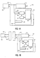
- Figure 4 shows a security system with a dynamic field of view and motion detection masking in accordance with this invention.
- the system- is described with reference to a direct connection between the monitor station and the camera and motion detector as shown in figure 4a.
- Figure 4b shows a system with a remote monitor station, for completeness.
- the system comprises elements similar in function to those in figures la and 3a.
- a camera 110 provides video images 101 to the monitor station 420 and motion detector 430.
- monitor station 420 comprises the ability to store a set of camera positions 450 and masks 460.
- Motion detector 430 in accordance with this invention, comprises the ability to replace the contents of its mask 135. As shown by the mask image signal 436, the monitor station can transmit a new mask image into the mask 135, replacing the prior mask.
- the monitor station 420 of figure 4 also transmits camera positioning commands 311 to the driver 370.
- the P/T/Z camera's field of view 112 is adjustable via the motors 360 which are controlled by the motor driver 370 in response to these camera positioning commands from the monitor station.
- the camera positioning commands in accordance with this invention, may come from direct commands, such as joystick movements or menu selections, as in figure 3, or from the set of positions 450, as will be discussed below.
- Figure 5 provides additional detail with regard to the monitor station 420.
- Means 510 are provided at the control station to create masks which can be downloaded to the motion detector.
- a mask is created in conjunction with the video images 101 received from the camera.
- Means 520 are provided to control the camera.
- the monitor will control the camera until a desired view is achieved.
- the video images produced by this view will be displayed to the monitor, and the monitor will select areas of this view to be masked.
- this masking will be accomplished by selecting segments of the video image, using, for example, a mouse, or a touch screen, to create a mask overlay. As is evident, this mask overlay will be specific to the particular image being viewed.
- the user may store the camera position which corresponds to this view, and the mask corresponding to this view, at a selected address 540.
- the address 540 could be a mere index, for example, View1, View2, and so on, but preferably could be more descriptive, such as FrontDoor, ParkingLot, etc.
- the monitor may then control the camera to produce a different view, create a mask corresponding to this new view, and save the camera position and mask corresponding to this view at another address.
- Each saved address, position, mask triplet will be saved as a related set, as depicted by address element 541, position element 451, and mask element 461, in figure 5.
- positions and masks will be created for a select set of views, covering the surveillance area as required.
- the operation of the system is straightforward.
- the monitor merely selects an address of interest.
- the monitor station transmits the corresponding camera positioning commands to steer the camera to the selected view, and transmits the corresponding mask image to the motion detector to appropriately mask sections of the images from the selected view.
- the motion detector or the monitor station may also be provided means for disabling alerts during camera movement, and reenabling the alerts when the camera ceases movement and the new mask is loaded, to prevent the false alerts typically caused by camera motion.
- the creation of the select views and masks is described above as a purely sequential process, i.e. define all the masks for all the views, then initiate the security functions by recalling one of the created views and masks, it is evident that not all views need be created before a created view may be utilized in a security mode.
- the set of select views is modifiable at any time, allowing the monitor to change the mask associated with a view, define a new select view and mask, or delete a previously defined select view and mask. In so doing, the system allows for changes to suit security requirements based, for example, on experience or changing conditions.
- the system in accordance with this invention provides for a dynamic camera field of view capability, with motion detection masking.
- Alternative embodiments will be evident to one versed in the art, consistent with this invention.
- the selection of areas within which to detect motion could be accomplished by selecting the areas of interest, rather than by excluding areas.
- the camera positioning commands could be actual P/T/Z motor movement commands, or "go-to" commands, depending upon the capabilities provided at the driver 370, or receiver/driver 365.
- the motion detector 430 may contain local memory for the storage of a set of masks, and the monitor station need merely transmit a "use N" command, to have the motion detector use mask N.
- the set of position-mask pairs corresponding to a particular view may be further addressed by the time of day, or day of the week, etc. That is, there may be areas associated with a view for which motion is expected only during certain time periods. For example, a bank counter may be masked for motion detection during normal business hours, but should not be masked when the bank is closed.
- multiple masks can be defined corresponding to the same view, same camera location, but having a different address, based on some other parameter, such as a time period. Consistent with this invention, as well, masking and alerting can be independently enabled and disabled, either directly, or dependent upon the time of day, or other parameters.
- the selection of views can be automated.
- the monitor station controller 580 can be programmed to routinely step through the set, or a subset, of views to maintain surveillance. This programming could include the selection of views dependent upon the time of day, or other parameters.
- aids could be provided in the creation of masks corresponding to particular views.
- the monitor may position the camera to a view which does not yet have a corresponding mask, but the camera's position may be between two positions which do have corresponding masks.
- the system could be programmed to create a mask for the intermediate position by interpolating the masks of the bounding positions.
- This interpolated mask could be provided to the monitor as the default mask corresponding to the intermediate position, as a starting point for creating a specific mask, or as the mask to be employed in lieu of a specific mask.
- the creation of a default mask could also be accomplished through the use of expert systems, pattern recognition, machine learning, or similar computer aids.
- the system could analyze a new view to determine if a pattern similar to the masked doorway exists in the new view. If it does, a default mask could be automatically created for this similar pattern, subject to the monitor's acceptance. The monitor is thereby relieved of the detail of creating masks for areas or features common to multiple scenes.
- the mask can be created or modified based upon actual movements in the view.
- Most motion detection systems provide the ability to mark the individual parts of the image in which motion was detected. If the monitor notes this movement to be irrelevant, and expects it to happen repeatedly, the monitor can instruct the system to add the portions of the image within which motion was detected to the current mask associated with the view. For example, an image may contain a large tree, the periphery of which triggers motion detection as the leaves move. Each time such movement is reported, the monitor can append the mask. Eventually, the mask will contain a periphery image of the tree.
- the system could also be provided with a means for saving an oversized mask. The picture elements within which motion is detected, as well as the picture elements immediately adjacent to these portions could be saved as the new or modified mask.
- a default mask could be created based upon the actual coordinate transformations corresponding to a modified view. That is, the areas masked in one or more views could be assigned coordinates relative to the camera. A new mask could be created at any chosen view by rotating the masked areas through the angles traversed by the camera, and magnifying or demagnifying the areas in correspondence with the changes in the camera's zoom. This transformed mask could be applied as the starting point for creating a specific mask, or as the mask to be employed in lieu of a specific mask.
- multiple cameras and motion detectors may be controlled by the same monitor station.
- the address of the stored positions and masks need merely be further delineated by the specific camera for which the stored position and mask apply.
- the motion detection means may be contained within the camera, or within the monitor station. Further, the motion detection means may be common to multiple cameras, requiring merely that the motion detection means maintain the appropriate association of masks for, and images from, each camera.
Claims (18)
- Überwachungssystem, das die nachfolgenden Elemente umfasst:eine Videokamera (110) mit einem einstellbaren Gesichtsfeld (112),einen Bewegungsdetektor (130) zum Detektieren von Bewegung innerhalb des Gesichtsfeldes (112) der Videokamera, wobei der genannte Bewegungsdetektor (130) eine Maske (135) aufweist zum Maskieren von Teilen des genannten Gesichtsfeldes der Videokamera gegenüber der genannten Bewegungsdetektion, und gekennzeichnet durch:Mittel (460) zum Selektieren eines Zielmaskenbildes (461) aus einem Satz von Zielmaskenbildern, und zwar in Abhängigkeit von dem genannten Gesichtsfeld (451) der Kamera, undMittel zum Laden des genannten Zielmaskenbildes (461) in die genannte Maske (135).
- Überwachungssystem nach Anspruch 1, wobei das genannte System weiterhin die nachfolgenden Elemente umfasst:einen Pan-Motor (360) zum "Pannen" der Videokamera über eine horizontale Achse,einen Tilt-Motor (360) zum "Tilten" der Videokamera über eine vertikale Achse, undeinen Zoom-Motor (360) zum Vergrößern und Verkleinern des Gesichtsfeldes der Videokamera.
- Überwachungssystem nach Anspruch 1, wobei das genannte System weiterhin die nachfolgenden Elemente umfasst:Mittel (360) zum Einstellen des Gesichtsfeldes der Kamera über einen oder mehrere Kamerapositionierungsbefehle (311),Mittel (366) zum Speichern eines Satzes von Kamerapositionierungsbefehlen, entsprechend dem Gesichtsfeld der Videokamera, in einem Speicher,Mittel (450) zum Selektieren eines Satzes von Zielpositionierungsbefehlen aus dem genannten Speicher,Mittel (370) für eine Kommunikation zwischen dem genannten Satz von Zielpositionierungsbefehlen und der Kamera, zum Einstellen des genannten Gesichtsfeldes der Kamera.
- Überwachungssystem nach Anspruch 3, wobei das genannte System weiterhin die nachfolgenden Elemente umfasst:wobei die genannten Mittel (450) zum Selektieren eines Satzes von Zielpositionierungsbefehlen und die genannten Mittel (460) zum Selektieren des Zielmaskenbildes beide unabhängig von dem selektierten Zielgesichtsfeld (540) sind.Mittel (540) zum Selektieren eines Zielgesichtsfeldes,
- Überwachungssystem nach Anspruch 1, wobei dieses System weiterhin die nachfolgenden Elemente umfasst:Mittel (510) zum Erzeugen und Speichern eines oder mehrerer Zielmaskenbilder entsprechend dem Gesichtsfeld der Kamera.
- Überwachungssystem nach Anspruch 5, wobei dieses System weiterhin die nachfolgenden Elemente umfasst:Mittel um in Abhängigkeit von einem Maskenselektionsparameter aus den maskierten Bildern, die dem gleichen Gesichtsfeld entsprechen, eine Selektion zu machen.
- Überwachungssystem nach Anspruch 6, wobei der genannte Maskenselektionsparameter die Tageszeit ist.
- Überwachungssystem nach Anspruch 6, wobei der genannte Maskenselektionsparameter der Wochentag ist.
- Überwachungssystem nach Anspruch 5, wobei die genannten Mittel (510) zum Erzeugen der genannten Zielmaskenbilder, die nachfolgenden Elemente umfassen:Mittel zum Erzeugen eines Maskenbildes in Abhängigkeit von einem vorher erzeugten Maskenbildes.
- Überwachungssystem nach Anspruch 5, wobei die genannten Mittel zum Erzeugen der genannten Zielmaskenbilder die nachfolgenden Elemente umfassen:Mittel zum Erzeugen eines Maskenbildes in Abhängigkeit von detektierter Bewegung innerhalb des Gesichtsfeldes der Kamera.
- Überwachungssystem nach Anspruch 1, wobei das genannte System weiterhin die nachfolgenden Elemente umfasst:Mittel zum Deaktivieren des Bewegungsdetektors, wenn das einstellbare Gesichtsfeld der Kamera eingestellt wird.
- Überwachungssystem nach Anspruch 1, wobei das genannte System weiterhin die nachfolgenden Elemente umfasst:Mittel zum Aktivieren des genannten Bewegungsdetektors bei Beendigung der genannten Ladung des Maskenbildes.
- Verfahren zur selektiven Gebietsbewegungsdetektion mit Hilfe eines Überwachungssystems nach einem der Ansprüche 1 - 12, wobei eine Kamera mit einem einstellbaren Gesichtsfeld und ein Bewegungsdetektor mit einer ladbaren Maske verwendet wird, wobei das genannte Verfahren die nachfolgenden Verfahrensschritte umfasst:das Einstellen der Kamera zum Erzeugen eines Gesichtsfeldes, unddas Laden eines Maskenbildes entsprechend dem genannten Gesichtsfeld in die genannte ladbare Maske.
- Verfahren zur selektiven Gebietsbewegungsdetektion nach Anspruch 13, wobei die genannte Einstellung der Kamera die nachfolgenden Verfahrensschritte umfasst:das Selektieren einer vordefinierten Kameraposition,das Mitteilen von Kamerapositionierungsbefehlen entsprechend dieser selektierten Position, unddas Einstellen der Kamera entsprechend den genannten Kamerapositionierungsbefehlen.
- Verfahren zur selektiven Gebietsbewegungsdetektion nach Anspruch 13, wobei das genannte Laden der Maske die nachfolgenden Verfahrensschritte umfasst:das Selektieren eines vordefinierten Maskenbildes entsprechend dem genannten Gesichtsfeld,das Mitteilen des selektierten Maskenbildes an den Bewegungsdetektor, unddas Laden des selektierten Maskenbildes in die ladbare Maske.
- Verfahren zur selektiven Gebietsbewegungsdetektion nach Anspruch 13, wobei die genannte Einstellung der Kamera die nachfolgenden Verfahrensschritte umfasst:das Selektieren einer vordefinierten Kameraposition,das Mitteilen von Kamerapositionierungsbefehlen entsprechend dieser selektierten Position, unddas Einstellen der Kamera entsprechend den genannten Kamerapositionierungsbefehlen, und wobei das genannte Laden der Maske die nachfolgenden Verfahrensschritte umfasst:das Selektieren eines vordefinierten Maskenbildes entsprechend dem genannten Gesichtsfeld,das Mitteilen des selektierten Maskenbildes an den Bewegungsdetektor unddas Laden des selektierten Maskenbildes in die ladbare Maske.
- Verfahren zur selektiven Gebietsbewegungsdetektion nach Anspruch 16, wobei die genannte Selektion der vordefinierten Kameraposition und die genannte Selektion des vordefinierten Maskenbildes erreicht wird durch:Selektion einer Adresse, mit der die genannte vordefinierte Kameraposition und das vordefinierte Maskenbild beide assoziiert sind.
- Verfahren zur selektiven Gebietsbewegungsdetektion nach Anspruch 13, wobei der genannte Ladeschritt eines Maskenbildes die nachfolgenden Verfahrensschritte umfasst:das Erzeugen einer Bildgebietsmaske für jeden genannten Gesichtspunkt der Kamera,das Speichern von Kameraparametern entsprechend jedem der genannten Gesichtspunkte der Kamera,das Speichern jeder Maske der genannten Bildgebietsmasken entsprechend jedem der genannten Gesichtsfelder der Kamera,das Einstellen der genannten Kamera entsprechend einem Parameter des Satzes der genannten gespeicherten Kameraparameter,das Laden der genannten gespeicherten Bildgebietsmaske entsprechend dem genannten Gesichtsfeld in den Bewegungsdetektor, unddas Anwenden der genannten Maske auf das genannte maskierbare Bildgebiet zum Erzeugen eines maskierten Bildgebietes, so dass eine nachfolgende Bewegungsdetektion durch den genannten Bewegungsdetektor nicht eine Bewegung innerhalb des maskierten Bildgebietes umfasst.
Applications Claiming Priority (3)
| Application Number | Priority Date | Filing Date | Title |
|---|---|---|---|
| US834073 | 1997-04-14 | ||
| US08/834,073 US6727938B1 (en) | 1997-04-14 | 1997-04-14 | Security system with maskable motion detection and camera with an adjustable field of view |
| PCT/IB1998/000482 WO1998047117A1 (en) | 1997-04-14 | 1998-04-02 | A security system with maskable motion detection and camera with an adjustable field of view |
Publications (2)
| Publication Number | Publication Date |
|---|---|
| EP0907940A1 EP0907940A1 (de) | 1999-04-14 |
| EP0907940B1 true EP0907940B1 (de) | 2003-07-02 |
Family
ID=25266035
Family Applications (1)
| Application Number | Title | Priority Date | Filing Date |
|---|---|---|---|
| EP98909686A Expired - Lifetime EP0907940B1 (de) | 1997-04-14 | 1998-04-02 | Sicherheitssystem mit maskierbarer bewegungsdetektion und kamera mit einstellbarem gesichtsfeld |
Country Status (6)
| Country | Link |
|---|---|
| US (1) | US6727938B1 (de) |
| EP (1) | EP0907940B1 (de) |
| JP (1) | JP2000513168A (de) |
| KR (1) | KR20000016631A (de) |
| DE (1) | DE69815981T2 (de) |
| WO (1) | WO1998047117A1 (de) |
Families Citing this family (99)
| Publication number | Priority date | Publication date | Assignee | Title |
|---|---|---|---|---|
| US7907793B1 (en) | 2001-05-04 | 2011-03-15 | Legend Films Inc. | Image sequence depth enhancement system and method |
| US8396328B2 (en) | 2001-05-04 | 2013-03-12 | Legend3D, Inc. | Minimal artifact image sequence depth enhancement system and method |
| US6317152B1 (en) * | 1999-07-17 | 2001-11-13 | Esco Electronics Corporation | Digital video recording system |
| AU2001240100A1 (en) * | 2000-03-10 | 2001-09-24 | Sensormatic Electronics Corporation | Method and apparatus for video surveillance with defined zones |
| CA2403270C (en) | 2000-03-14 | 2011-05-17 | Joseph Robert Marchese | Digital video system using networked cameras |
| US6992723B1 (en) | 2000-06-30 | 2006-01-31 | Sensormatic Electronics Corporation | Integrated enclosure for video surveillance camera |
| US6850025B1 (en) | 2000-06-30 | 2005-02-01 | Sensormatic Electronics Corporation | Integrated enclosure and controller for video surveillance camera |
| US7868912B2 (en) * | 2000-10-24 | 2011-01-11 | Objectvideo, Inc. | Video surveillance system employing video primitives |
| US8711217B2 (en) * | 2000-10-24 | 2014-04-29 | Objectvideo, Inc. | Video surveillance system employing video primitives |
| US8564661B2 (en) | 2000-10-24 | 2013-10-22 | Objectvideo, Inc. | Video analytic rule detection system and method |
| US9892606B2 (en) * | 2001-11-15 | 2018-02-13 | Avigilon Fortress Corporation | Video surveillance system employing video primitives |
| US20050146605A1 (en) * | 2000-10-24 | 2005-07-07 | Lipton Alan J. | Video surveillance system employing video primitives |
| US6841780B2 (en) * | 2001-01-19 | 2005-01-11 | Honeywell International Inc. | Method and apparatus for detecting objects |
| US7176440B2 (en) | 2001-01-19 | 2007-02-13 | Honeywell International Inc. | Method and apparatus for detecting objects using structured light patterns |
| US8897596B1 (en) | 2001-05-04 | 2014-11-25 | Legend3D, Inc. | System and method for rapid image sequence depth enhancement with translucent elements |
| US9031383B2 (en) | 2001-05-04 | 2015-05-12 | Legend3D, Inc. | Motion picture project management system |
| US8401336B2 (en) | 2001-05-04 | 2013-03-19 | Legend3D, Inc. | System and method for rapid image sequence depth enhancement with augmented computer-generated elements |
| MXPA03010039A (es) * | 2001-05-04 | 2004-12-06 | Legend Films Llc | Sistema y metodo para mejorar la secuencia de imagen. |
| US9286941B2 (en) | 2001-05-04 | 2016-03-15 | Legend3D, Inc. | Image sequence enhancement and motion picture project management system |
| US20030004913A1 (en) * | 2001-07-02 | 2003-01-02 | Koninklijke Philips Electronics N.V. | Vision-based method and apparatus for detecting an event requiring assistance or documentation |
| DE10158990C1 (de) * | 2001-11-30 | 2003-04-10 | Bosch Gmbh Robert | Videoüberwachungssystem |
| US7161615B2 (en) * | 2001-11-30 | 2007-01-09 | Pelco | System and method for tracking objects and obscuring fields of view under video surveillance |
| JP3704706B2 (ja) * | 2002-03-13 | 2005-10-12 | オムロン株式会社 | 三次元監視装置 |
| JP3996805B2 (ja) * | 2002-06-06 | 2007-10-24 | 株式会社日立製作所 | 監視カメラ装置、監視カメラシステム装置及び撮像画面のマスク方法 |
| FR2842637B1 (fr) * | 2002-07-22 | 2004-10-01 | Citilog | Procede pour detecter un incident ou analogue sur une portion de voie |
| US20040021778A1 (en) * | 2002-08-05 | 2004-02-05 | Oldani Jerome L. | Security system with remote access and control |
| US20040100563A1 (en) | 2002-11-27 | 2004-05-27 | Sezai Sablak | Video tracking system and method |
| US7889113B2 (en) * | 2003-10-10 | 2011-02-15 | L-3 Communications Security and Detection Systems Inc. | Mmw contraband screening system |
| US8558892B2 (en) * | 2004-01-20 | 2013-10-15 | Honeywell International Inc. | Object blocking zones to reduce false alarms in video surveillance systems |
| US7742077B2 (en) * | 2004-02-19 | 2010-06-22 | Robert Bosch Gmbh | Image stabilization system and method for a video camera |
| US7382400B2 (en) | 2004-02-19 | 2008-06-03 | Robert Bosch Gmbh | Image stabilization system and method for a video camera |
| US7643066B2 (en) * | 2004-02-19 | 2010-01-05 | Robert Bosch Gmbh | Method and apparatus for producing frame accurate position data in a PTZ dome camera with open loop control |
| US9210312B2 (en) | 2004-06-02 | 2015-12-08 | Bosch Security Systems, Inc. | Virtual mask for use in autotracking video camera images |
| US8212872B2 (en) | 2004-06-02 | 2012-07-03 | Robert Bosch Gmbh | Transformable privacy mask for video camera images |
| KR100694283B1 (ko) | 2004-11-05 | 2007-03-14 | 텔미정보통신 주식회사 | 이미지 프로세싱을 이용한 pc 기반의 영상 인식 방법 |
| KR100719120B1 (ko) * | 2005-02-26 | 2007-05-17 | 삼성전자주식회사 | 프라이버시영역을 마스크 처리하는 감시시스템 및 그 방법 |
| US9077882B2 (en) | 2005-04-05 | 2015-07-07 | Honeywell International Inc. | Relevant image detection in a camera, recorder, or video streaming device |
| WO2006132029A1 (ja) * | 2005-06-07 | 2006-12-14 | Matsushita Electric Industrial Co., Ltd. | 監視システム、監視方法及びカメラ端末 |
| US20070040891A1 (en) * | 2005-08-17 | 2007-02-22 | Jacob Calloway | Community message board |
| US20070115355A1 (en) * | 2005-11-18 | 2007-05-24 | Mccormack Kenneth | Methods and apparatus for operating a pan tilt zoom camera |
| US20070116328A1 (en) * | 2005-11-23 | 2007-05-24 | Sezai Sablak | Nudity mask for use in displaying video camera images |
| EP1804511A1 (de) * | 2005-12-30 | 2007-07-04 | Nederlandse Organisatie voor Toegepast-Natuuurwetenschappelijk Onderzoek TNO | Überwachungssystem, Verfahren zur Überwachung, Computersystem und Computerprogrammprodukt |
| US9166883B2 (en) | 2006-04-05 | 2015-10-20 | Joseph Robert Marchese | Network device detection, identification, and management |
| CN101087405A (zh) * | 2006-06-07 | 2007-12-12 | 鸿富锦精密工业(深圳)有限公司 | 动态监控系统及方法 |
| US20070291104A1 (en) * | 2006-06-07 | 2007-12-20 | Wavetronex, Inc. | Systems and methods of capturing high-resolution images of objects |
| JP4706573B2 (ja) * | 2006-06-29 | 2011-06-22 | 日本ビクター株式会社 | 動き検出装置及び動き検出方法 |
| US8451329B2 (en) * | 2006-08-14 | 2013-05-28 | Honeywell International Inc. | PTZ presets control analytics configuration |
| US8947526B2 (en) * | 2006-12-07 | 2015-02-03 | Sensormatic Electronics, LLC | Video surveillance system having communication acknowledgement nod |
| US20080177646A1 (en) * | 2007-01-19 | 2008-07-24 | Property Monitors, Inc. | Work site remote monitoring and employee time tracking system and method |
| TWI369135B (en) * | 2007-12-31 | 2012-07-21 | Nat Applied Res Lab Nat Ct For High Performance Computing | Camera control system capable of positioning and tracking object in space and method thereof |
| US20090237509A1 (en) * | 2008-03-21 | 2009-09-24 | Vibrashine, Inc. | Motion activated camera system |
| JP5264582B2 (ja) * | 2008-04-04 | 2013-08-14 | キヤノン株式会社 | 監視装置、監視方法、プログラム、及び記憶媒体 |
| JP5456022B2 (ja) * | 2008-04-14 | 2014-03-26 | ジーブイビービー ホールディングス エス.エイ.アール.エル. | オブジェクトを自動的に追跡する技術 |
| US8311275B1 (en) | 2008-06-10 | 2012-11-13 | Mindmancer AB | Selective viewing of a scene |
| KR101538654B1 (ko) * | 2008-07-07 | 2015-07-22 | 삼성전자주식회사 | 손 떨림 보정 동작을 제어하는 디지털 촬영장치 및 이의제어방법 |
| JP5030882B2 (ja) * | 2008-07-25 | 2012-09-19 | 三菱電機株式会社 | 監視用画像処理装置 |
| EP2202533A1 (de) * | 2008-12-23 | 2010-06-30 | IBEO Automobile Sensor GmbH | Erfassungsvorrichtung |
| KR101676437B1 (ko) * | 2009-05-01 | 2016-11-15 | 코닌클리케 필립스 엔.브이. | 이미지 기반 조명 제어 및 보안 제어를 위한 시스템 및 장치 |
| FR2951571A1 (fr) * | 2009-10-16 | 2011-04-22 | Cecilia Leroy Garnier | Dispositif de surveillance et d'alerte par parcellisation et traitement d'une image numerique |
| JP2011097487A (ja) * | 2009-11-02 | 2011-05-12 | Hitachi Kokusai Electric Inc | 画像監視装置 |
| US9041800B2 (en) | 2009-12-30 | 2015-05-26 | Robert Bosch Gmbh | Confined motion detection for pan-tilt cameras employing motion detection and autonomous motion tracking |
| JP2010137097A (ja) * | 2010-03-23 | 2010-06-24 | Namco Bandai Games Inc | ゲーム装置および情報記憶媒体 |
| JP5643552B2 (ja) * | 2010-06-28 | 2014-12-17 | キヤノン株式会社 | 撮像装置 |
| US8692884B2 (en) * | 2010-09-17 | 2014-04-08 | Gish Technology, Inc. | Apparatus and method for assessing visual acuity |
| US8730232B2 (en) | 2011-02-01 | 2014-05-20 | Legend3D, Inc. | Director-style based 2D to 3D movie conversion system and method |
| US9407904B2 (en) | 2013-05-01 | 2016-08-02 | Legend3D, Inc. | Method for creating 3D virtual reality from 2D images |
| US9282321B2 (en) | 2011-02-17 | 2016-03-08 | Legend3D, Inc. | 3D model multi-reviewer system |
| US9288476B2 (en) | 2011-02-17 | 2016-03-15 | Legend3D, Inc. | System and method for real-time depth modification of stereo images of a virtual reality environment |
| US9113130B2 (en) | 2012-02-06 | 2015-08-18 | Legend3D, Inc. | Multi-stage production pipeline system |
| US9241147B2 (en) | 2013-05-01 | 2016-01-19 | Legend3D, Inc. | External depth map transformation method for conversion of two-dimensional images to stereoscopic images |
| US8773501B2 (en) | 2011-06-20 | 2014-07-08 | Duco Technologies, Inc. | Motorized camera with automated panoramic image capture sequences |
| JP5921331B2 (ja) * | 2012-05-21 | 2016-05-24 | キヤノン株式会社 | 撮像装置、マスク画像の重畳方法、および、プログラム |
| SE537427C2 (sv) * | 2012-08-20 | 2015-04-28 | Mindmancer AB | Metod och datorprogramprodukt för övervakningssystem och övervakningssystem |
| US9007365B2 (en) | 2012-11-27 | 2015-04-14 | Legend3D, Inc. | Line depth augmentation system and method for conversion of 2D images to 3D images |
| US9547937B2 (en) | 2012-11-30 | 2017-01-17 | Legend3D, Inc. | Three-dimensional annotation system and method |
| US9299234B2 (en) * | 2013-01-09 | 2016-03-29 | Nicole R. Haines | Security apparatus and system |
| KR101288881B1 (ko) * | 2013-02-18 | 2013-07-23 | 에이치디씨 주식회사 | 다수의 감시영역을 설정하고 이를 확대촬영할 수 있는 감시카메라의 감시영역 설정시스템 |
| US9007404B2 (en) | 2013-03-15 | 2015-04-14 | Legend3D, Inc. | Tilt-based look around effect image enhancement method |
| US9438878B2 (en) | 2013-05-01 | 2016-09-06 | Legend3D, Inc. | Method of converting 2D video to 3D video using 3D object models |
| TWI530917B (zh) * | 2013-08-23 | 2016-04-21 | 貝思親健康事業股份有限公司 | 獨居者安全通報裝置 |
| US9544491B2 (en) | 2014-06-17 | 2017-01-10 | Furuno Electric Co., Ltd. | Maritime camera and control system |
| CN105450918B (zh) * | 2014-06-30 | 2019-12-24 | 杭州华为企业通信技术有限公司 | 一种图像处理方法和摄像机 |
| US9779307B2 (en) * | 2014-07-07 | 2017-10-03 | Google Inc. | Method and system for non-causal zone search in video monitoring |
| US10140827B2 (en) | 2014-07-07 | 2018-11-27 | Google Llc | Method and system for processing motion event notifications |
| WO2016157330A1 (ja) * | 2015-03-27 | 2016-10-06 | 日本電気株式会社 | モバイル監視装置、プログラム、及び制御方法 |
| US9569874B2 (en) * | 2015-06-05 | 2017-02-14 | International Business Machines Corporation | System and method for perspective preserving stitching and summarizing views |
| US9361011B1 (en) | 2015-06-14 | 2016-06-07 | Google Inc. | Methods and systems for presenting multiple live video feeds in a user interface |
| US9609307B1 (en) | 2015-09-17 | 2017-03-28 | Legend3D, Inc. | Method of converting 2D video to 3D video using machine learning |
| JP6218872B2 (ja) * | 2016-03-18 | 2017-10-25 | キヤノン株式会社 | 監視装置、情報処理装置、監視装置の処理方法及びプログラム |
| US10506237B1 (en) | 2016-05-27 | 2019-12-10 | Google Llc | Methods and devices for dynamic adaptation of encoding bitrate for video streaming |
| US10957171B2 (en) | 2016-07-11 | 2021-03-23 | Google Llc | Methods and systems for providing event alerts |
| WO2018081328A1 (en) * | 2016-10-26 | 2018-05-03 | Ring Inc. | Customizable intrusion zones for audio/video recording and communication devices |
| US11354786B2 (en) | 2017-10-10 | 2022-06-07 | Robert Bosch Gmbh | Method for masking an image of an image sequence with a mask, computer program, machine-readable storage medium and electronic control unit |
| US10186124B1 (en) | 2017-10-26 | 2019-01-22 | Scott Charles Mullins | Behavioral intrusion detection system |
| MX2021012393A (es) * | 2019-04-10 | 2022-03-17 | Scott Charles Mullins | Sistemas de monitoreo. |
| RU2701092C1 (ru) * | 2019-04-22 | 2019-09-24 | Общество с ограниченной ответственностью "Ай Ти Ви групп" | Система и способ сопровождения движущихся объектов |
| US11323633B2 (en) | 2019-07-01 | 2022-05-03 | Bendix Commercial Vehicle Systems, Llc | Automated creation of a freeform mask for automotive cameras |
| EP3985976B1 (de) | 2020-10-16 | 2022-09-28 | Axis AB | Verfahren zur codierung eines bildes mit einer privatsphärenmaske |
| KR102314903B1 (ko) * | 2021-05-25 | 2021-10-19 | 김유성 | 영상 기반 건물 제어 방법 및 장치 |
Family Cites Families (18)
| Publication number | Priority date | Publication date | Assignee | Title |
|---|---|---|---|---|
| CA1116286A (en) * | 1979-02-20 | 1982-01-12 | Control Data Canada, Ltd. | Perimeter surveillance system |
| JPS6360960B2 (de) * | 1980-10-22 | 1988-11-25 | ||
| JPS61113377A (ja) * | 1984-11-07 | 1986-05-31 | Sony Corp | テレビジヨン信号の動き検出装置 |
| US5111288A (en) * | 1988-03-02 | 1992-05-05 | Diamond Electronics, Inc. | Surveillance camera system |
| US4931868A (en) * | 1988-05-31 | 1990-06-05 | Grumman Aerospace Corporation | Method and apparatus for detecting innovations in a scene |
| US5091780A (en) * | 1990-05-09 | 1992-02-25 | Carnegie-Mellon University | A trainable security system emthod for the same |
| GB2245741A (en) * | 1990-06-27 | 1992-01-08 | Philips Electronic Associated | Active matrix liquid crystal devices |
| US5243418A (en) * | 1990-11-27 | 1993-09-07 | Kabushiki Kaisha Toshiba | Display monitoring system for detecting and tracking an intruder in a monitor area |
| JP2974520B2 (ja) * | 1991-10-25 | 1999-11-10 | キヤノン株式会社 | 電極基板及び液晶素子 |
| JP2667940B2 (ja) * | 1992-04-27 | 1997-10-27 | 三菱電機株式会社 | マスク検査方法およびマスク検出装置 |
| US5365355A (en) * | 1993-03-10 | 1994-11-15 | Wah-Iii Technology Corporation | Light blocking, pixel enhancement and photocurrent reduction in active matrix liquid crystal displays |
| US5396284A (en) * | 1993-08-20 | 1995-03-07 | Burle Technologies, Inc. | Motion detection system |
| JP3574170B2 (ja) * | 1994-03-17 | 2004-10-06 | 富士通株式会社 | 分散型画像処理装置 |
| US5521634A (en) * | 1994-06-17 | 1996-05-28 | Harris Corporation | Automatic detection and prioritized image transmission system and method |
| US5517236A (en) * | 1994-06-22 | 1996-05-14 | Philips Electronics North America Corporation | Video surveillance system |
| GB2305061B (en) * | 1994-07-26 | 1998-12-09 | Maxpro Systems Pty Ltd | Text insertion system |
| US5526041A (en) * | 1994-09-07 | 1996-06-11 | Sensormatic Electronics Corporation | Rail-based closed circuit T.V. surveillance system with automatic target acquisition |
| US5652667A (en) * | 1995-02-03 | 1997-07-29 | Victor Company Of Japan, Ltd. | Liquid crystal display apparatus |
-
1997
- 1997-04-14 US US08/834,073 patent/US6727938B1/en not_active Expired - Lifetime
-
1998
- 1998-04-02 EP EP98909686A patent/EP0907940B1/de not_active Expired - Lifetime
- 1998-04-02 JP JP10529384A patent/JP2000513168A/ja active Pending
- 1998-04-02 KR KR1019980710227A patent/KR20000016631A/ko active IP Right Grant
- 1998-04-02 WO PCT/IB1998/000482 patent/WO1998047117A1/en active IP Right Grant
- 1998-04-02 DE DE69815981T patent/DE69815981T2/de not_active Expired - Fee Related
Also Published As
| Publication number | Publication date |
|---|---|
| KR20000016631A (ko) | 2000-03-25 |
| JP2000513168A (ja) | 2000-10-03 |
| WO1998047117A1 (en) | 1998-10-22 |
| DE69815981D1 (de) | 2003-08-07 |
| EP0907940A1 (de) | 1999-04-14 |
| DE69815981T2 (de) | 2004-05-19 |
| US6727938B1 (en) | 2004-04-27 |
Similar Documents
| Publication | Publication Date | Title |
|---|---|---|
| EP0907940B1 (de) | Sicherheitssystem mit maskierbarer bewegungsdetektion und kamera mit einstellbarem gesichtsfeld | |
| US8289392B2 (en) | Automatic multiscale image acquisition from a steerable camera | |
| US9041800B2 (en) | Confined motion detection for pan-tilt cameras employing motion detection and autonomous motion tracking | |
| US6359647B1 (en) | Automated camera handoff system for figure tracking in a multiple camera system | |
| US5980123A (en) | System and method for detecting an intruder | |
| EP1765014B1 (de) | Überwachungskamera und Kameraüberwachungssystem | |
| CA2149730C (en) | Rail-based closed circuit t.v. surveillance system with automatic target acquisition | |
| US20100013917A1 (en) | Method and system for performing surveillance | |
| US20050036036A1 (en) | Camera control apparatus and method | |
| WO2004038659A2 (en) | Method and system for performing surveillance | |
| US20080117296A1 (en) | Master-slave automated video-based surveillance system | |
| US20080122930A1 (en) | Image processor, intruder monitoring apparatus and intruder monitoring method | |
| JPH08265741A (ja) | ビデオ式区域監視装置及び方法 | |
| KR100849689B1 (ko) | 영상자동팝업기능이 구비된 감시통제시스템 및 그 제어방법 | |
| EP3452848B1 (de) | Überwachungsverfahren unter verwendung eines kamerasystems mit einer bereichsbewegungsdetektion | |
| US20030103138A1 (en) | Video security and control system | |
| US20020052708A1 (en) | Optimal image capture | |
| KR20110075250A (ko) | 객체 추적 모드를 활용한 객체 추적 방법 및 장치 | |
| JP3929161B2 (ja) | 画像監視システム | |
| WO1999035850A1 (en) | Multiple camera system | |
| CN113068000B (zh) | 视频目标的监控方法、装置、设备、系统及存储介质 | |
| JP2006178515A (ja) | 検知エリア表示機能付き侵入検知装置 | |
| WO2005120070A2 (en) | Method and system for performing surveillance | |
| JPH11275566A (ja) | 監視カメラ装置 | |
| KR20110079953A (ko) | 감시 영역 설정을 통한 객체 감시 방법 및 장치 |
Legal Events
| Date | Code | Title | Description |
|---|---|---|---|
| PUAI | Public reference made under article 153(3) epc to a published international application that has entered the european phase |
Free format text: ORIGINAL CODE: 0009012 |
|
| AK | Designated contracting states |
Kind code of ref document: A1 Designated state(s): DE FR GB NL |
|
| 17P | Request for examination filed |
Effective date: 19990422 |
|
| 17Q | First examination report despatched |
Effective date: 20020313 |
|
| GRAH | Despatch of communication of intention to grant a patent |
Free format text: ORIGINAL CODE: EPIDOS IGRA |
|
| GRAH | Despatch of communication of intention to grant a patent |
Free format text: ORIGINAL CODE: EPIDOS IGRA |
|
| GRAA | (expected) grant |
Free format text: ORIGINAL CODE: 0009210 |
|
| AK | Designated contracting states |
Designated state(s): DE FR GB NL |
|
| REG | Reference to a national code |
Ref country code: GB Ref legal event code: FG4D |
|
| RAP2 | Party data changed (patent owner data changed or rights of a patent transferred) |
Owner name: ROBERT BOSCH GMBH |
|
| REF | Corresponds to: |
Ref document number: 69815981 Country of ref document: DE Date of ref document: 20030807 Kind code of ref document: P |
|
| NLT2 | Nl: modifications (of names), taken from the european patent patent bulletin |
Owner name: ROBERT BOSCH GMBH |
|
| PGFP | Annual fee paid to national office [announced via postgrant information from national office to epo] |
Ref country code: GB Payment date: 20040319 Year of fee payment: 7 |
|
| ET | Fr: translation filed | ||
| PGFP | Annual fee paid to national office [announced via postgrant information from national office to epo] |
Ref country code: FR Payment date: 20040422 Year of fee payment: 7 |
|
| PGFP | Annual fee paid to national office [announced via postgrant information from national office to epo] |
Ref country code: NL Payment date: 20040423 Year of fee payment: 7 |
|
| PLBE | No opposition filed within time limit |
Free format text: ORIGINAL CODE: 0009261 |
|
| STAA | Information on the status of an ep patent application or granted ep patent |
Free format text: STATUS: NO OPPOSITION FILED WITHIN TIME LIMIT |
|
| PGFP | Annual fee paid to national office [announced via postgrant information from national office to epo] |
Ref country code: DE Payment date: 20040614 Year of fee payment: 7 |
|
| 26N | No opposition filed |
Effective date: 20040405 |
|
| PG25 | Lapsed in a contracting state [announced via postgrant information from national office to epo] |
Ref country code: GB Free format text: LAPSE BECAUSE OF NON-PAYMENT OF DUE FEES Effective date: 20050402 |
|
| PG25 | Lapsed in a contracting state [announced via postgrant information from national office to epo] |
Ref country code: NL Free format text: LAPSE BECAUSE OF NON-PAYMENT OF DUE FEES Effective date: 20051101 Ref country code: DE Free format text: LAPSE BECAUSE OF NON-PAYMENT OF DUE FEES Effective date: 20051101 |
|
| GBPC | Gb: european patent ceased through non-payment of renewal fee |
Effective date: 20050402 |
|
| PG25 | Lapsed in a contracting state [announced via postgrant information from national office to epo] |
Ref country code: FR Free format text: LAPSE BECAUSE OF NON-PAYMENT OF DUE FEES Effective date: 20051230 |
|
| NLV4 | Nl: lapsed or anulled due to non-payment of the annual fee |
Effective date: 20051101 |
|
| REG | Reference to a national code |
Ref country code: FR Ref legal event code: ST Effective date: 20051230 |