EP0907224A1 - Groupe batterie de voiture - Google Patents
Groupe batterie de voiture Download PDFInfo
- Publication number
- EP0907224A1 EP0907224A1 EP97936856A EP97936856A EP0907224A1 EP 0907224 A1 EP0907224 A1 EP 0907224A1 EP 97936856 A EP97936856 A EP 97936856A EP 97936856 A EP97936856 A EP 97936856A EP 0907224 A1 EP0907224 A1 EP 0907224A1
- Authority
- EP
- European Patent Office
- Prior art keywords
- plug
- slider
- plug housing
- leaf
- end portion
- Prior art date
- Legal status (The legal status is an assumption and is not a legal conclusion. Google has not performed a legal analysis and makes no representation as to the accuracy of the status listed.)
- Withdrawn
Links
Images


Classifications
-
- H—ELECTRICITY
- H01—ELECTRIC ELEMENTS
- H01R—ELECTRICALLY-CONDUCTIVE CONNECTIONS; STRUCTURAL ASSOCIATIONS OF A PLURALITY OF MUTUALLY-INSULATED ELECTRICAL CONNECTING ELEMENTS; COUPLING DEVICES; CURRENT COLLECTORS
- H01R24/00—Two-part coupling devices, or either of their cooperating parts, characterised by their overall structure
- H01R24/58—Contacts spaced along longitudinal axis of engagement
Definitions
- the present invention relates to an automotive battery plug that is fitted into an automotive cigar lighter socket and electrically connected thereto to supply power to portable equipment carried in a motor vehicle.
- Fig. 10 is a diagrammatic representation of the construction of a conventional automotive battery plug indicated generally by 100, which has a cylindrical plug housing 101 and an insulating cap 102 threadably attached to the forward end portion of the plug housing 101.
- the insulating cap 102 has a through hole 102a, through which a head terminal 103 is inserted in a manner to be movable back and forth. As shown, a shoulder 103a of the head terminal 103 abuts against a stepped portion formed in the through hole 102 to limit outward movement of the head terminal 103.
- the head terminal 103 has in its rear end a circularly-sectioned recess 103b opening rearward, which receives a tip-end terminal 106a of a fuse tube 106, establishing electric connections between the terminal 106a and the head terminal 103.
- a fixed terminal 105 Disposed in the plug housing 101 centrally thereof is a fixed terminal 105, which is fixed to the plug housing 101 through a stationary part 104 formed integrally therewith.
- the fixed terminal 105 has its leg 105a extended rearward and soldered to a power-supply lead wire of a power cord not shown.
- the fixed terminal 105 has a pair of opposed arms 105b, which have their opposing surfaces concavely curved and receive or hold therebetween a conductive coiled spring 107.
- the head terminal 103 is electrically connected via the fuse tube 106 and the conductive coiled spring 107 to the fixed terminal 105 which is electrically connected to the power-side lead wire of the power cord.
- the fuse tube 106 forms a overcurrent protection circuit.
- leaf-spring contact pieces 108 each having its free end portion arcuately bowed or bent inward in a U-letter shape.
- One of the leaf-spring coils 108 has its leg 108a extended backward and soldered to a grounding lead wire of the power cord, though not shown.
- Each leaf-spring contact piece 108 has its leg 108a fixedly fitted in a groove 101a made in the plug housing 101 so that its circularly arcuate contact portion 108b protrudes from the periphery of the plug housing 101 through an opening 109 made in one side thereof.
- each leaf-spring contact piece 108 abuts against the outer wall surface 101b of the plug housing 101 which is aligned with the opening 109.
- the plug housing 101 comprises a pair of axially-divided half shells, which are joined together by threading a screw (not shown) into a tapped hole 110 after putting the fixed terminal 105, the leaf-spring contact pieces 108 and other parts in one of the half shells ad then covering it with the other half shell.
- the contact portions 108b of the leaf-spring contact pieces 108 make resilient contact with the inner wall of a cylindrical grounding terminal 111a, and when the battery body 100 is further pushed into the socket 111, the head terminal 103 is pressed into resilient contact with a power terminal 111b partly exposed on the inner end face of the socket 111.
- the grounding terminal 111a and power terminal 111b of the cigar lighter socket 111 are electrically connected via the battery plug 100 to the grounding and power-supply lead wires of the power cord, respectively.
- the leaf-spring contact pieces 108 have their base end portions fixedly held in the grooves 101a of the plug housing 101 and their arcuately bowed free end portions held in abutment with the outer wall surface 101b of the plug housing 101, with the contact portions 108b protruding far from the plug housing 101 through the opening 109. Accordingly, the contact portions 108b resiliently contact the cylindrical grounding terminal 111a of the cigar lighter socket 111 with a sufficient contact pressure, and the automotive battery plug 100 will not readily come out the cigar lighter socket 111.
- the force for pulling out the battery plug 100 from the cigar lighter socket 111 could be reduced by changing the shapes of the leaf-spring contact pieces 108 or the positions where to mount them in the plug housing 101. This, however, gives rise to the problem of insufficient contact pressure between the contact pieces 108 and the cylindrical grounding terminal 111a and hence insecure retention of the plug 100 in the socket 111. Accordingly, it is impossible with the prior art to meet contradictory requirements of a firm retention of the automotive battery plug 100 in the cigar lighter socket 111 and easy removal of the former from the latter.
- an automotive battery plug which comprises: a cylindrical plug housing for insertion into a cigar lighter socket; a pair of leaf-spring contact pieces each having its base portion fixed in the cylindrical plug housing ad its free end portion bent into a U-letter shape so that a outside contact portion extending from the base portion protrudes from the periphery of the plug housing through a opening thereof and an inside return end portion lies in the plug housing; a slider disposed in the plug housing in a manner to be slidable lengthwise thereof, either side surface of the slider resiliently contacting the return end portion of the leaf-spring contact piece; support portion formed in either side surface of the slider for resilient contact with the return end portion, the return end portion sliding into abutment with the support portion when the slider slides forward; a inclined portion formed in either side surface of the slider and contiguous to the support portion along the front edge thereof so that when the slider slides backward, the return end portion slides down a slope into the plug housing; and an operating knob exposed on a grip of the
- each leaf-spring contact piece When the automotive battery plug is pulled out of the cigar lighter socket, the return end portion of each leaf-spring contact piece is retracted into the plug housing by the operating knob moved backward.
- the operating knob exposed on the grip of the plug housing is moved forward by the user's finger during the manual operation for fitting the plug into the socket.
- the slider slides forward in the plug housing, causing the return end portions of the leaf-spring contact pieces to abut against the support portions on the both side surfaces of the slider.
- the operating knob In the case of pulling out the automotive battery plug from the cigar lighter socket, the operating knob is moved rearward by the user's finger during the manual operation for removing the plug from the socket.
- the leaf-spring contact pieces can be electrically connected to the grounding terminal of the cigar lighter socket with a sufficient contact pressure thereto, and in this state, the battery plug will not readily come off the cigar lighter socket. On the other hand, the battery plug can be pulled out of the socket with ease without any particularly large force.
- a return spring is disposed in the plug housing to urge the slider toward the forward portion of the plug housing so that the return end portions of the leaf-spring contact pieces in its nomal state abut against the support portions on both side surfaces of the slider.
- the operating knob In the case of pulling out the battery plug from the cigar lighter socket, the operating knob is moved rearward against the spring action of the return spring, causing the returned portions of the leaf-spring contact pieces to slide on the slopes of the inclined portions. As a result, the return end portions of the contact pieces go into the plug housing, allowing removal of the battery plug from the socket with a small amount of force.
- the contact portions of the contact pieces are adjusted by the return spring automatically to protrude to their outermost positions through the openings, they can be electrically connected to the grounding terminal of the cigar lighter socket with a sufficient contact pressure without involving any particular preadjustment.
- the support portion on either side surface of the slider has cut therein a positioning groove for engagement with the return end portion of the leaf-spring contact piece.
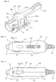
- Figs. 1 and 2 are horizontal and longitudinal sectional views depicting the automotive battery plug 1 prior to insertion into the cigar lighter socket 111.
- the plug housing 2 is formed in one piece of a insulating synthetic resin material.
- the plug housing 2 comprises a pair of molded upper and lower half shells 2a and 2b. These half shells 2a and 2b are joined together by inserting a tap bolt 3 through the upper half shell 2a and then screwing it into a tapped hole made in the lower half shell 2b so that there is formed in the plug housing 1 a space where to place a fuse tube 16, a printed-circuit board 6 and so forth.
- Figs. 1 are horizontal and longitudinal sectional views depicting the automotive battery plug 1 prior to insertion into the cigar lighter socket 111.
- the plug housing 2 is formed in one piece of a insulating synthetic resin material.
- the plug housing 2 comprises a pair of molded upper and lower half shells 2a and 2b. These half shells 2a and 2b are joined together by inserting a
- the front half portion of the plug housing 2 is an insert portion 21 that is inserted into a cigar lighter socket, and the rear half portion forms a grip 22.
- the top of grip 22 of the plug housing 2 there is formed an elongated operating aperture 23, through which an operating knob 24 described later on slightly juts out.
- a insulating cap 5 Threadably attached to an opening in the tip of the insert portion 21 of the plug housing 2, as shown in Figs. 1 to 4, is a insulating cap 5 molded of insulating synthetic resin. Since the insulating cap 5 is removable from the tip of the plug body 2, a fuse in the fuse tube 16, if burnt, could easily be replaced with a new one.
- the insulating cap 5 has a centrally-disposed cylindrical hole which has an annular stepped portion formed in its inside wall surface over the entire circumference thereof and in which a head terminal 9 is retractably received.
- the head terminal 9 has a cylindrical but hollow body made of a conductive metal, and a flange 9a at its rear end abuts the above-mentioned annular stepped portion to prevent the head terminal 9 from coming out of the hole in the forward direction (to the left in Fig. 1).
- the interior of the head terminal 9 forms a circular cross-section cavity 10, wherein the front end portion of a conductive coiled spring 11 is received.
- the head terminal 9, which supports the conductive coiled spring 11, is inserted through the cylindrical hole of the insulating cap 5 from behind to a position where the flange 9a of the head terminal 9 abuts the annular stepped portion on the interior surface of the hole ad the head terminal 9 retractably extends out of the tip of the insulating cap 5.
- the printed-circuit board 6 has its perimeter contoured following the inside surface of the lower half shell 2b.
- the printed-circuit board 6 is positioned relative to the lower half shell 2b by a boss 12 plated thereon and inserted through a positioning hole bored through the printed-circuit board 6 centrally thereof.
- a grounding contact 14 and a fixed terminal 15 which are electrically connected to a grounding lead and a power-supply lead (not shown) of a power cord 13 respectively via patterns formed on the underside of the printed-circuit board 6.
- the fixed terminal 15 is a conductive plate formed by stamping a sheet metal into a desired shape and subjecting it to simple bending.
- the fixed terminal 15 has a downward leg portion, which extends through the printed-circuit board 6 and is soldered to a power-supply pattern on the underside thereof.
- the fuse tube 16 abuts against the fixed terminal 15 from the front, but a support piece 18 extending down from the upper half shell 2a of the plug housing 2 supports the fixed terminal 15 on the back thereof to prevent it from falling rearward.
- the fuse tube 16 is received in a guide flame 8 of a U-shaped cross-section, formed as a unitary structure with the lower half shell 2b, and is disposed in the plug housing 2 lengthwise thereof.
- the conductive coiled spring 11 is held compressed by placing the fuse tube 16 between the fixed terminal 15 and the coiled spring 11.
- a slider 25 is mounted on the guide frame 8 in a manner to be slidable thereon in the lengthwise (front-to-back) direction of the plug housing 2.
- the slider 25 has on either side thereof a laterally projecting support portion 25a and an inclined portion 25b contiguous to the support portion 25a along the forward edge thereof and forming a inwardly slating slope 26 in the forward direction.
- a vertically extending positioning groove 27 in which a return end portion 17b of a leaf-spring contact piece 17, which abuts against the support portion 25a, is received and hence positioned as described later on.
- the aforementioned operating knob 24 Molded integrally with the rear end portion of the slider 25 on the top thereof is the aforementioned operating knob 24, which is manually moved back and forth to shift the position of the slider 25. That is, the slider 25 is operatively associated with the operating knob 24.
- the operating knob 24 is inserted in the elongated operating aperture 23 of the upper half shell 2a from below and slightly juts out upwardly thereof for manual back-and-forth motion.
- the slider 25 is urged forward by a compressed return spring 29 interposed between the rear end face of the slider 25 and the lower half shell 2b of the plug housing 2 as shown in Figs. 1 and 2.
- the grounding contact 14 is formed by bending a strip of conductive and resilient metal into substantially arch shape as shown in Fig. 1, in which the leaf-spring contact pieces 17 extend forward from opposite ends of its base portion 14a.
- the central portion of the lower side of the base portion 14a extends down through the printed-circuit board 6, and is soldered to a grounding pattern formed on the underside thereof.
- the grounding contact 14 is electrically connected via the grounding pattern to the grounding lead wire as referred to previously.
- the remaining marginal portions of the lower side of the base portion 14a, except its downward extending central portion, are bent rearward at right angles to form a horizontal support piece 14c, supporting the base portion 14a upright on the printed-circuit board 6.
- the pair of leaf-spring contact pieces 17 have their free end portions arcuately bowed or curved in substantially U-letter shape so that their circularly arcuate contact portions 17a protrude from the periphery of the plug housing 2 through openings 17a made in the opposite sides thereof.
- the free end portions of the leaf-spring contact pieces 17 bent backward in the plug housing 2 form the return end portions 17b.
- the free ends of the return end portions 17b each extend into the plug housing 2 and resiliently contact one side surface of the slider 25. Since the slider 25 moves back and forth in the plug housing 2, the position of abutment of the free end of the return end portion 17b with the side surface of the slider 25 also shifts with its movement.
- the slider 25 is held at a position nearest to the front end of the guide frame 8 under the action of the return spring 29.
- the return end portion 17b of each leaf-spring contact piece 17 abuts against the slider 25 at the support portion 25a and engages the positioning groove 27 cut in the support portion 25a.
- the slider 25 When the battery plug 1 is not fitted in the cigar lighter socket 111, the slider 25 is urged forward by the return spring 29 along the guide frame 8 and held at its foremost position, and consequently, the return end portion 17b of each leaf-spring contact piece 17 is in engagement with the positioning groove 27 cut in the support portion 25a of the slider 25. Since the support portion 25a is further to the outside than the slider body, the contact portions 17a of the leaf-spring contact pieces 17 greatly protrude through the openings 19.
- the contact portions 17a of the leaf-spring contact pieces 17 resiliently contact a cylindrical grounding terminal 111a of the socket 111 with appropriate contact pressure, providing positive retention of the battery plug 1 in the socket 111.
- the grounding terminal 111a is electrically connected to a grounding lead wire of the power cord 13 via the leaf-spring contact pieces 17, the base portion 14a of the grounding contact 14 and the grounding pattern of the printed-circuit board 6, and when the battery plug 1 is further pushed into the socket 111, the head terminal 9 is pressed into resilient contact with a power-supply terminal 111b formed on the inner end face of the socket 111.
- the power-supply terminal 111b is electrically connected to a power-supply lead wire of the power cord 13 via the head terminal 9, the conductive coiled spring 11, the fuse tube 16, the fixed terminal 15 and the power-supply pattern formed on the printed-circuit board 6.
- the operating knob 24, which is exposed on the grip 22, is naturally slid backward by the user's finger along the operating aperture 23 against the spring action of the return spring 29.
- the battery plug 1 can easily be removed from the cigar lighter socket 111 with a very small amount of force.
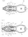
- Figs. 8 and 9 illustrate a automotive battery plug 30 according to a second embodiment of the present invention, which is identical in construction with the plug 1 of the first embodiment except the side configuration of a slider 31.
- the parts corresponding to those in the first embodiment are identified by the same reference numerals ad no description will be given of them.
- each leaf-spring contact piece 17 slides down the slope 26 and into abutment with the side surface of the slider 25 at a position inner than a support portion 31a of the slider 31.
- the return end portion 17b slides down a slope 32 and gets out of contact with the side surface of the slider 31 and into abutment with the guide frame 8 as shown in Fig. 9.
- the position of the return end portion 17b can be changed vertically by making the return end portion 17b abut against the support portion 31a of the slider 31 or the guide frame 8. This provides increased difference between the plug retentive force and the force for removing the plug 1 from the socket 111 without increasing the thickness of the slider 31, that is, without upsizing the plug housing 2.
- the return spring 29 has been described to be used to urge the sliders 25 and 31 forward for automatic return to their initial positions, but the return spring 29 need not always be provided when the car battery plug 1 is adapted to automatically move the operating knob 24 forward at the time of fitting the battery 1 into the cigar lighter socket 111.
- the return spring 29 is not limited specifically to the coiled spring but may be a leaf spring or mold spring molded from synthetic resin as long as they urge the sliders 25 and 31 or the operating knob 24 forward at any times.
- the slider 25 or 31 and the operating knob 24 are formed as a unitary structure with each other, they may be formed separately and coupled together by means of screws. Alternatively, they may be operatively associated with each other through some other coupling members.
- slider 25 is guided lengthwise of the plug housing 2 by the U-shaped guide frame 8 molded integrally with the lower half shell 2b, but it may be guided directly by the plug housing 2 by forming the slider 25 so that its shape of projection in the front-to-back direction conforms to the inner wall surface of the cylindrical plug housing 2.
- the automotive battery plug according to the present invention is suitable for use as a plug which is fitted in an automotive cigar lighter socket to feed power to vehicle-mounted portable equipment.
Landscapes
- Coupling Device And Connection With Printed Circuit (AREA)
Applications Claiming Priority (3)
| Application Number | Priority Date | Filing Date | Title |
|---|---|---|---|
| JP9106845A JP3065558B2 (ja) | 1997-04-10 | 1997-04-10 | カーバッテリープラグ |
| JP106845/97 | 1997-04-10 | ||
| PCT/JP1997/002920 WO1998045903A1 (fr) | 1997-04-10 | 1997-08-22 | Groupe batterie de voiture |
Publications (2)
| Publication Number | Publication Date |
|---|---|
| EP0907224A1 true EP0907224A1 (fr) | 1999-04-07 |
| EP0907224A4 EP0907224A4 (fr) | 2001-02-07 |
Family
ID=14444000
Family Applications (1)
| Application Number | Title | Priority Date | Filing Date |
|---|---|---|---|
| EP97936856A Withdrawn EP0907224A4 (fr) | 1997-04-10 | 1997-08-22 | Groupe batterie de voiture |
Country Status (4)
| Country | Link |
|---|---|
| US (1) | US6135798A (fr) |
| EP (1) | EP0907224A4 (fr) |
| JP (1) | JP3065558B2 (fr) |
| WO (1) | WO1998045903A1 (fr) |
Cited By (2)
| Publication number | Priority date | Publication date | Assignee | Title |
|---|---|---|---|---|
| DE202009010499U1 (de) * | 2009-08-03 | 2010-12-16 | Dometic Waeco International Gmbh | Steckvorrichtung nach Art eines Zigarettenanzündersteckers, insbesondere für Kraftfahrzeuge |
| CN111048961A (zh) * | 2018-10-15 | 2020-04-21 | 东京Cosmos电机株式会社 | 连接插头 |
Families Citing this family (10)
| Publication number | Priority date | Publication date | Assignee | Title |
|---|---|---|---|---|
| US7070435B2 (en) * | 2002-11-06 | 2006-07-04 | George Stephen Ramsay | Electrical safety plug and socket |
| US6902437B1 (en) * | 2003-09-29 | 2005-06-07 | Chin-Yang Wang | Removable fastening mechanism connectable to socket of cigar lighter of automobile |
| US20050148230A1 (en) * | 2004-01-07 | 2005-07-07 | Flynn James D. | Coupling device that includes opposing pawls engagable into opposing pawl catches |
| US7292881B2 (en) * | 2004-09-08 | 2007-11-06 | Belkin International, Inc. | Holder, electrical supply, and RF transmitter unit for electronic devices |
| JP2009054547A (ja) * | 2007-08-29 | 2009-03-12 | Toshiba Corp | コネクタプラグ |
| US8070503B2 (en) * | 2009-05-26 | 2011-12-06 | Spin Master Ltd. | Charging interface for rechargeable devices |
| TWM388781U (en) * | 2010-04-19 | 2010-09-11 | Powertech Industrialco Ltd | Car charger |
| US8547056B2 (en) * | 2011-01-06 | 2013-10-01 | Ching-Chih Chang | One-piece car charger |
| TWI487638B (zh) * | 2012-11-16 | 2015-06-11 | Delta Electronics Inc | 車用充電器 |
| JP5897065B2 (ja) * | 2014-05-28 | 2016-03-30 | 三菱電機株式会社 | 電子機器ユニット |
Citations (2)
| Publication number | Priority date | Publication date | Assignee | Title |
|---|---|---|---|---|
| US5263879A (en) * | 1992-02-25 | 1993-11-23 | Smk Corporation | Automotive cigar lighter plug |
| WO1997007570A1 (fr) * | 1995-08-18 | 1997-02-27 | Smk Co., Ltd. | Fiche de raccordement pour automobiles |
Family Cites Families (8)
| Publication number | Priority date | Publication date | Assignee | Title |
|---|---|---|---|---|
| JPS6071084U (ja) * | 1983-10-24 | 1985-05-20 | 星電器製造株式会社 | ロツク機構付コネクタ |
| JPH0530307Y2 (fr) * | 1987-02-12 | 1993-08-03 | ||
| JPH0587856U (ja) * | 1991-02-18 | 1993-11-26 | デルタ工業株式会社 | シガープラグ |
| JP2551887B2 (ja) * | 1991-12-04 | 1996-11-06 | 英朗 茂治 | 電源取出用のカープラグ |
| JP2525339Y2 (ja) * | 1992-10-01 | 1997-02-12 | エスエムケイ株式会社 | カーバッテリープラグ |
| US5261838A (en) * | 1993-01-06 | 1993-11-16 | Smk Corporation | Automotive cigar lighter plug with stopper |
| JP3022591U (ja) * | 1995-09-11 | 1996-03-26 | 英朗 茂治 | カープラグ |
| JP3110335B2 (ja) * | 1997-01-08 | 2000-11-20 | 英朗 茂治 | カープラグ |
-
1997
- 1997-04-10 JP JP9106845A patent/JP3065558B2/ja not_active Expired - Lifetime
- 1997-08-22 WO PCT/JP1997/002920 patent/WO1998045903A1/fr not_active Application Discontinuation
- 1997-08-22 EP EP97936856A patent/EP0907224A4/fr not_active Withdrawn
- 1997-08-22 US US09/202,148 patent/US6135798A/en not_active Expired - Fee Related
Patent Citations (2)
| Publication number | Priority date | Publication date | Assignee | Title |
|---|---|---|---|---|
| US5263879A (en) * | 1992-02-25 | 1993-11-23 | Smk Corporation | Automotive cigar lighter plug |
| WO1997007570A1 (fr) * | 1995-08-18 | 1997-02-27 | Smk Co., Ltd. | Fiche de raccordement pour automobiles |
Non-Patent Citations (1)
| Title |
|---|
| See also references of WO9845903A1 * |
Cited By (3)
| Publication number | Priority date | Publication date | Assignee | Title |
|---|---|---|---|---|
| DE202009010499U1 (de) * | 2009-08-03 | 2010-12-16 | Dometic Waeco International Gmbh | Steckvorrichtung nach Art eines Zigarettenanzündersteckers, insbesondere für Kraftfahrzeuge |
| WO2011015340A1 (fr) | 2009-08-03 | 2011-02-10 | Dometic Waeco International Gmbh | Dispositif enfichable sous forme d'une fiche d'allume-cigare, en particulier pour des véhicules automobiles |
| CN111048961A (zh) * | 2018-10-15 | 2020-04-21 | 东京Cosmos电机株式会社 | 连接插头 |
Also Published As
| Publication number | Publication date |
|---|---|
| WO1998045903A1 (fr) | 1998-10-15 |
| JPH10284185A (ja) | 1998-10-23 |
| US6135798A (en) | 2000-10-24 |
| JP3065558B2 (ja) | 2000-07-17 |
| EP0907224A4 (fr) | 2001-02-07 |
Similar Documents
| Publication | Publication Date | Title |
|---|---|---|
| US6135798A (en) | Automotive battery plug | |
| US6923666B1 (en) | Electrical plug changer | |
| US5486123A (en) | Connector terminal | |
| EP0279359A1 (fr) | Fiche de jack à support d'élément optique | |
| US2954544A (en) | Electrical plug connectors | |
| JP2002507828A (ja) | 異種接続系用マルチプルプラグ | |
| EP0788195B1 (fr) | Fiche de raccordement pour automobiles | |
| CA2195332A1 (fr) | Allume-cigare electrique pourvu a l'arriere d'une fiche de connexion et d'assemblage | |
| CN113629412B (zh) | 一种接线端子及接线端子排 | |
| EP0860908A1 (fr) | Prise de batterie pour automobile | |
| US5884530A (en) | Shift knob structure | |
| JP2002015824A (ja) | カープラグおよびカープラグの外極端子 | |
| US3925655A (en) | Composite map light and cigar lighter plug | |
| JPH0722133A (ja) | ランプソケット | |
| JP3014033B2 (ja) | 自動車用コネクタプラグ | |
| JPH0869745A (ja) | 筒型ヒューズホルダ | |
| JPS6115581Y2 (fr) | ||
| AU719831B2 (en) | Connector plug for automobiles | |
| US5239145A (en) | Pin jack | |
| JP3737831B2 (ja) | 自動車用アンテナ | |
| JP2000184667A (ja) | ブラシ摩耗報知装置 | |
| JPH0336058Y2 (fr) | ||
| JPH028401B2 (fr) | ||
| JP2591682Y2 (ja) | 電源用コネクタ | |
| JPH0963713A (ja) | 自動車用コネクタプラグ |
Legal Events
| Date | Code | Title | Description |
|---|---|---|---|
| PUAI | Public reference made under article 153(3) epc to a published international application that has entered the european phase |
Free format text: ORIGINAL CODE: 0009012 |
|
| 17P | Request for examination filed |
Effective date: 19981120 |
|
| AK | Designated contracting states |
Kind code of ref document: A1 Designated state(s): DE FR GB |
|
| A4 | Supplementary search report drawn up and despatched |
Effective date: 20001228 |
|
| AK | Designated contracting states |
Kind code of ref document: A4 Designated state(s): DE FR GB |
|
| RIC1 | Information provided on ipc code assigned before grant |
Free format text: 7H 01R 17/04 A, 7H 01R 17/18 B |
|
| 17Q | First examination report despatched |
Effective date: 20010806 |
|
| STAA | Information on the status of an ep patent application or granted ep patent |
Free format text: STATUS: THE APPLICATION IS DEEMED TO BE WITHDRAWN |
|
| 18D | Application deemed to be withdrawn |
Effective date: 20011218 |