EP0907094B1 - Brille - Google Patents
Brille Download PDFInfo
- Publication number
- EP0907094B1 EP0907094B1 EP97914621A EP97914621A EP0907094B1 EP 0907094 B1 EP0907094 B1 EP 0907094B1 EP 97914621 A EP97914621 A EP 97914621A EP 97914621 A EP97914621 A EP 97914621A EP 0907094 B1 EP0907094 B1 EP 0907094B1
- Authority
- EP
- European Patent Office
- Prior art keywords
- spectacles
- temple
- pads
- bridge
- nose
- Prior art date
- Legal status (The legal status is an assumption and is not a legal conclusion. Google has not performed a legal analysis and makes no representation as to the accuracy of the status listed.)
- Expired - Lifetime
Links
Images


Classifications
-
- G—PHYSICS
- G02—OPTICS
- G02C—SPECTACLES; SUNGLASSES OR GOGGLES INSOFAR AS THEY HAVE THE SAME FEATURES AS SPECTACLES; CONTACT LENSES
- G02C1/00—Assemblies of lenses with bridges or browbars
- G02C1/02—Bridge or browbar secured to lenses without the use of rims
-
- G—PHYSICS
- G02—OPTICS
- G02C—SPECTACLES; SUNGLASSES OR GOGGLES INSOFAR AS THEY HAVE THE SAME FEATURES AS SPECTACLES; CONTACT LENSES
- G02C11/00—Non-optical adjuncts; Attachment thereof
-
- G—PHYSICS
- G02—OPTICS
- G02C—SPECTACLES; SUNGLASSES OR GOGGLES INSOFAR AS THEY HAVE THE SAME FEATURES AS SPECTACLES; CONTACT LENSES
- G02C3/00—Special supporting arrangements for lens assemblies or monocles
- G02C3/003—Arrangements for fitting and securing to the head in the position of use
-
- G—PHYSICS
- G02—OPTICS
- G02C—SPECTACLES; SUNGLASSES OR GOGGLES INSOFAR AS THEY HAVE THE SAME FEATURES AS SPECTACLES; CONTACT LENSES
- G02C5/00—Constructions of non-optical parts
- G02C5/02—Bridges; Browbars; Intermediate bars
- G02C5/06—Bridges; Browbars; Intermediate bars with resilient means
-
- G—PHYSICS
- G02—OPTICS
- G02C—SPECTACLES; SUNGLASSES OR GOGGLES INSOFAR AS THEY HAVE THE SAME FEATURES AS SPECTACLES; CONTACT LENSES
- G02C5/00—Constructions of non-optical parts
- G02C5/12—Nose pads; Nose-engaging surfaces of bridges or rims
- G02C5/122—Nose pads; Nose-engaging surfaces of bridges or rims with adjustable means
-
- G—PHYSICS
- G02—OPTICS
- G02C—SPECTACLES; SUNGLASSES OR GOGGLES INSOFAR AS THEY HAVE THE SAME FEATURES AS SPECTACLES; CONTACT LENSES
- G02C5/00—Constructions of non-optical parts
- G02C5/14—Side-members
- G02C5/143—Side-members having special ear pieces
-
- G—PHYSICS
- G02—OPTICS
- G02C—SPECTACLES; SUNGLASSES OR GOGGLES INSOFAR AS THEY HAVE THE SAME FEATURES AS SPECTACLES; CONTACT LENSES
- G02C5/00—Constructions of non-optical parts
- G02C5/14—Side-members
- G02C5/16—Side-members resilient or with resilient parts
-
- G—PHYSICS
- G02—OPTICS
- G02C—SPECTACLES; SUNGLASSES OR GOGGLES INSOFAR AS THEY HAVE THE SAME FEATURES AS SPECTACLES; CONTACT LENSES
- G02C2200/00—Generic mechanical aspects applicable to one or more of the groups G02C1/00 - G02C5/00 and G02C9/00 - G02C13/00 and their subgroups
- G02C2200/10—Frame or frame portions made from wire
Definitions
- the present invention relates to new spectacles which are light, are easily handled and reduce a discomfort when the spectacles are put on.
- the spectacles comprise two lenses, a frame surrounding the lenses, a bridge connecting between the lenses, temple arms extending from the lenses to upper ear portions and earpieces connected to the temple arms so as to be put behind the ears.
- the whole large and heavy spectacles would not only give the discomfort to a user with spectacles on, but also give a sense of fatigue to the user who uses the spectacles for a long time. Accordingly, the spectacles which are as compact and light as possible and are comfortable for the user are required.
- the spectacles are frequently put on and taken off, the simple handling thereof is required. Moreover, even if the spectacles are toughly handled, it requires that they are not easily deformed and damaged.
- the generally used spectacles are the spectacles in which a shape memory alloy capable of maintaining a specific shape which is not easily deformed and comprise a light material is used for the bridge and the temple arm, and the spectacle using a plastic lens lighter than a glass lens.
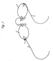
- Fig. 1 shows the spectacles disclosed in U.S. Patent No. 718,363.
- a metal wire material is used for the bridge connecting between the lenses, a rim supporting the lenses and a so-called temple arm used for putting on the spectacles on the face.
- the spectacles since the spectacles are held at both the ears and both the side portions of the nose by the earpieces, the spectacles must be put on and taken off by grasping and expanding the temple arms by hands. Accordingly, there is such a problem that a deformation is generated due to an excessive force applied to the temple arms. Furthermore, since the temple arm is one thin wire material, there is another problem that the whole spectacles are deformed when grasped, and the spectacles are hard to grasp.
- JP-U-03-043625 and JP-U-61-188119 disclose spectacles with temple arms arranged to contact pit regions of the temples of both sides of the prehead.
- US 1,914,971 discloses an eyeglass structure that has a resilient connecting member between two lenses for holding the eyeglass structure on the nose of the wearer.
- the spectacles which are attached to the head by wires without fixing by the earpieces and the spectacles which are simply held on the nose.
- the former has such a problem that it takes a complicated labor to attach the wires to the head and the wires are obstructive when the spectacles are accommodated.
- the latter has such a problem that the spectacles cannot be surely held on the face.
- the present invention is made so as to solve the problems.
- spectacles as defined in claim 1 whereby four pads hold the spectacles on the face.
- the four pads are used, the two pads of them push on both the sides of the nose and the other two pads push on the pit regions of the temples at both the sides of the head, whereby the spectacles are supported on the face at total four points.
- the portion in contact with a human being is considerably reduced, compared to the conventional spectacles, a discomfort to the human being due to the contact can be reduced.
- the pads are pushed on the pit regions so as to support the spectacles, the spectacles can be stably held.
- the spectacles having two grips.
- the grips can be held between fingers.
- the bridge is flexed with the center portion of the bridge as the center so that the distances between the two temple arms and between the two temple pads may be spaced.
- the grips return where they were by means of an elastic force of the bridge. Accordingly, while a user is simply grasping the grips, the user carries the spectacles near the face.
- the user simply releases his hold of the grips at a suitable position for fitting the spectacles on the face, that is, where the nose pads are positioned at both the sides of the nose and the temple pads are positioned at the pit regions of both the temples, whereby the user can easily put on the spectacles.
- the spectacles are taken off, the contrary procedure can be simply carried out.
- the grips are simply grasped and pushed so as to put on and take off the spectacles, an inadvertent deformation of the temple arms as usual can be avoided.
- the bridge and the temple arms comprise an elastic material.
- the material is a metal wire material having a spring characteristic, a shape memory alloy containing a nickel and titanium and having a high memory or a carbon fiber whose main component is a carbon having high elasticity, heat insulation and chemical resistance.
- the bridge and the temple arms can be made of a thin wire material, and it is possible to provide the spectacles which are light and gives less discomfort to the user.
- the pads can be sufficiently ensured to be pushed on both the sides of the nose and both the pit regions of the temples at both the sides of the face, it is possible to provide the spectacles which can be surely held at four points alone.
- each pad is a disk-shaped silicon material having some thickness so as to be provided with an elasticity.
- Flat portion of the pads are in contact with the nose and the pit regions of the temples, whereby a friction between a skin and the pads becomes stronger, so that the spectacles are not easily slipped down.
- a plastic material may be used for the bridge and the temple arms.
- the end portions of the temple pads extending from the lenses are used as the temple pads as it is so that the end portions may push on the pit regions of the temples.
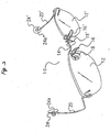
- Fig. 2 shows a general view of spectacles (10) according to an embodiment of the present invention.
- Respective end portions of two symmetrical lenses (12, 12') for both eyes are connected to a bridge (14) so that the lenses (12, 12') may be symmetrical about the bridge (14).
- Two nose pads (18, 18') are disposed near both the ends of the bridge (14).
- Temple arms (20, 20') are mounted to both the outer ends of the lenses (12, 12'), respectively.
- Temple pads (24, 24') are mounted to the edges of the temple arms (20, 20'), respectively.
- each of the bridge (14) and the temple arms (20, 20') is one elastic metal wire, whereby the whole spectacles (10) are intended to be lightened. Constitutions of the bridge (14) and the temple arms (20, 20') will be independently described in detail.
- the spectacles (10) are held on a face by four pads, that is, the two nose pads (18, 18') and two temple pads (24, 24').
- the spectacles are supported on the face at four points, whereby the spectacles can be put on on the face.
- an area where the spectacles are in contact with the face is reduced, a user's discomfort due to the contact of the spectacles with the face can be reduced.
- the temple pads (24, 24') are disposed in such a manner that they are just positioned at pit regions of the temples at both the ends of the user's head. Since the temples are pitted at the tails of eyebrows, the temple pads (24, 24') are received at the pit regions. Furthermore, the temple arms (20, 20') give an appropriate inward elasticity to the temple pads (24, 24'), whereby the spectacles (10) are held at the position on the face. In such a manner, the nose pads (18, 18') push on both the sides of the nose, and the temple pads (24, 24') being received at the pit regions of the temples push on the pit regions, whereby the spectacles (10) are not easily slipped down the face.
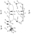
- Figs. 3A, 3B and 3C show an elevational view, a side view and a top view of the spectacles (10) shown in Fig. 2, respectively.
- the temple arms (20, 20') are inclined upward at the back of the lenses and extended in such a manner that the temple pads (24, 24') are just positioned at the pit regions of the human temples.
- the temple pads (24, 24') are mounted at the ends of the temple arms (20, 20').
- the nose pads (18, 18') are inclined to each other and are mounted to the bridge (14) so that they may be in contact with both the sides of the nose and may support the spectacles (10).
- the necessary length and inclination for the temple arms (20, 20') extending from the lenses (12, 12') to the pit regions is different in accordance with the size and shape of the face of the user using the spectacles (10). Accordingly, the temple arms (20, 20') may be made and used for each user. Furthermore, some kinds of temple arms (20, 20') having different sizes may be previously prepared, and optimum temple arms (20, 20') for the user may be selected and be used among them.
- the average temple arms (20, 20') obtained by the average value of the distance and position from the eye to the pit region of the temple. The reason is that since the distance between the eye and the pit region of the temple is short, a dispersion of the distance and position due to the different user is small. Furthermore, another reason is that the pit region has more or less extension.
- the nose pads (18, 18') and the temple pads (24, 24') are made from a silicon, and have more or less thick elastic disk shape.
- one side of the nose pads (18, 18') is mounted to extending nose arms (17, 17') splitted from the bridge (14) and the end portion of the temple arms (20, 20').
- the other side of the nose pads (18, 18') has a bottom portion in contact with the side of the nose and the pit region of the temple.
- a fitting mechanism is used that the pads can flexibly move to some extent at the end portion of the arm in such a manner that the pit regions of the temples or the side portions of the nose are in contact with the surfaces of bottom portions of the pads.
- This example shows the pads which are directly fixed and mounted to the arms.
- the shape and material of the nose pads (18, 18') and the temple pads (24, 24') and the mechanism for fitting the pads to the arm are not limited to the above example except for the case limited by Claims. As far as they are not harmful to a human being, any method and means may be used.
- the distance between the temple pads (24, 24') keep shorter than the distance between both the end portion of the temples of the user's head.
- the bridge (14) and the temple arms (20, 20') generate a stress for attempting to put the outward extended temple pads (24, 24') back where they were.
- the temple pads (24, 24') are pushed from outside onto the pit regions of the temples, so that the spectacles are held on the face. Accordingly, as shown by the temple pads (24, 24') in Fig.
- bottom portions (24a, 24a') of the temple pads (24, 24') are slightly inward directed and the temple arms (20, 20') also are slightly inward curved on the way to the temple pads (24, 24') so that the temple pads (24, 24') may be parallel to the pit regions of the temples of the head.
- the nose pads (18, 18') are supported.
- the nose pads (18, 18') are inclined and spaced from each other at a certain distance.
- Fig. 4A shows a side view of the bridge (14) and the nose pad (18) mounted to the bridge (14).
- Fig. 4B shows a top view of Fig. 4A.
- the whole bridge (14) comprises one metal wire material.
- the edge of the bridge (14) passes through a hole (15) bored through the lens (12).
- the metal wire extending backward from the hole (15), that is, toward the nose pad (18) draws a first U-shape (14a) on the way and turns back, so that the metal wire is in contact with the side end of the lens (12) and it proceeds forward, that is, in direction which the lens (12) is directed to.
- the metal wire draws a next U-shape (14b) and turns back, so that the metal wire is in contact with the side end of the lens (12) and it proceeds backward.
- the metal wire of the bridge (14) pinches the lens by the elasticity thereof at three points including the hole and the two contact portions of the side ends of the lenses, whereby the bridge (14) and the lens (12) are fixed and connected to each other.
- the metal wire extending backward from the lens (12) draws a further U-shape (14c) on the way, and the metal wire turned up so that it may avoid contacting with the nose.
- the metal wire is directed to the other lens (12'), and the metal wire is constructed symmetrically to the metal wire extended from the lens (12), so that the metal wire passes through a hole (15') bored through the other lens (12') and it is fixed and connected.
- the nose arms (17, 17') are splitted from one part of the first U-shapes (14a, 14a') and extended, and the nose pads (18, 18') are mounted to the edges of the nose arms (17, 17').
- the two nose pads (18, 18') are inclined and face each other in such a manner that both the sides of the nose are parallel to pad bottom portions (18a, 18a') of the nose pads (18, 18').
- the distance between the nose pads (18, 18') keeps such a distance that the nose pads (18, 18') are in contact with the sides of the nose.
- the material of the nose arms (17, 17') is the same as that of the bridge (14).
- a method for connecting the nose arms (17, 17') to the bridge (14) is not specifically important for the present invention, any method may be used.
- Figs. 4A and 4B show the example that the nose arms (17, 17') are splitted from the bridge (14), the present invention is not limited to this.
- the nose arms (17, 17') may be connected to the lenses (12, 12') and may be extended.
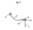
- Fig. 5 shows a side view of the temple arm (20) shown in Fig. 2 and the temple pad (24) mounted to the temple arm (20). Since the other temple arm (20') and temple pad (24') are the same as the temple arm (20) and the temple pad (24) to be described below except for the symmetrical shape thereto, the description is omitted.
- the temple arm (20) comprising one elastic metal wire material passes through a hole (22) bored at the outer end portion of the lens (12).
- the metal wire extending backward from the hole (22), that is, toward the temple pad (24) draws a first U-shape (20a) and turns back, so that the metal wire is in contact with the outer side end of the lens (12), and it proceeds forward, that is, in direction which the lens (12) is directed to. Furthermore, the wire metal draws a next U-shape (20b) and turns back, so that the metal wire is in contact with the outer side end of the lens (12), and it proceeds backward.
- the metal wire pinches the lens by the elasticity thereof at three points including the hole (22) and the two contact portions of the side ends of the lenses, whereby the temple arm (20) and the lens (12) are fixed and connected to each other.
- the metal wire passing the outer side end of the lens (12) and extending backward curves outward on the way so that it may avoid contacting with the head side portion. Thenceforth, as shown in Fig. 5, the metal wire are gently curved upward, and extends to the pit region of the temple of the head. Furthermore, as shown in Fig. 2, when the spectacles (10) are put on, while the metal wire are curved inward so that it may avoid contacting with the head side portion, it extends in a horizontal direction.
- the temple pad (24) is mounted to the extended edge of the metal wire just at the pit region of the temple.
- the whole spectacles (10) can be lightened.
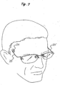
- Fig. 7 shows an example of the face with spectacles (10) on.
- the temple pads of the spectacles (10) are just in contact with and fixed to the pit regions of the temples, and the nose pads are support by both the upper sides of the nose.
- the metal wire material constituting the temple arms (20, 20') may be the same metal wire material having the elasticity as used for the bridge (14). Furthermore, a shape memory alloy which is light, has a restoring force and enables to push the pads onto the face may be used.
- the known shape memory alloy contains a nickel and a titanium in the substantial same ratio, and this alloy may be used.
- a carbon material having an elastic characteristic for example, a carbon fiber may be used for the bridge (14) and the temple arms (20, 20'). Furthermore, if the material is so elastic that the spectacles (10) can be held on the face by four pads, a plastic material and other material having a spring characteristic may be used.
- any shape and material of the pads may be used as limited by Claims. That is, any shape and material which enables to push both the sides of the nose and the pit regions of the temples may be used.
- protrusions formed by the second U-shape (14b) are grips (16, 16').
- the grips (16, 16') allows the user to easily put on or take off the spectacles. When the spectacles are put on or taken off, the grips (16, 16') prevents an excessive deformation of the temple arms.
- the constitution of the grips (16, 16') will be described below.
- the grips (16, 16') extend from the first U-shapes (14a, 14a'), and they cross over the lenses (12, 12').
- the grips (16, 16') being slightly outward curved form the U-shapes (14b, 14b'), and they turn back.
- U-shapes cross over the lenses (12, 12') and are protruded in order to ensure the region to be pinched by fingers. Accordingly, preferably, the U-shapes (14b, 14b') have such a size as to just fit fingertips. Furthermore, as shown in Fig. 4B, the grips (16, 16') are slightly curved so that the edge portions thereof may be expanded. This reason is that the edge portions are in contact with a bulb of the fingertip so that the grips can be firmly pushed when the grips are pinched.
- FIG. 6 shows a change of the position of the whole bridge (14), the nose pads (18, 18') and the lenses (12, 12') when the grips (16, 16') are pinched inward between the fingers.
- inward forces shown by arrows A, A'
- the forces are transmitted near a bridge center portion (14d) via third U-shaped portions (14c, 14c').
- the forces concentrated near the bridge center portion (14d) repulse from each other, and moments having the force in opposite directions relative to a support near the bridge center portion (14d) are generated at both the sides of the bridge (14).
- the bridge (14) is curved so that one grips (16) may be rotated counterclockwise and the other grips (16') may be rotated clockwise. Accordingly, the U-shapes (14c, 14a and 14c', 14a') formed at the opposite position to the grips (16, 16') are deformed so that they may be expanded outward. In accordance with the deformation, the nose pads (18, 18') are also opened outward as shown by arrows. Furthermore, the change allows one lens (12) to rotate counterclockwise, and the change allows the other lens (12') to rotate clockwise. Therefore, the temple arms (20, 20') mounted to the other end of the lenses (12, 12') shown in Figs.
- the temple pads (24, 24') are also moved in accordance with the rotating movement, and the distance between the temple pads (24, 24') is expanded. Since the temple arms (20, 20') are much longer than the grips (16, 16'), even if the grips (16, 16') are slightly changed, the distance between the temple pads (24, 24') is expanded substantially proportionally to the length of the temple arms (20, 20').
- the grips (16, 16') are held between the fingers, and the spectacles (10) are carried in front of the user's face.
- the distances between the nose pads (18, 18') and between the temple pads (24, 24') are expanded. With the distances open, the nose pads (18, 18') and the temple pads (24, 24') are carried at both the sides of the nose and the pit regions of the temples, respectively.
- the fingers are separated from the grips (16, 16').
- the bridge (14) and the temple arms (20, 20') are intended to recover where they were. Accordingly, the nose pads (18, 18') and the temple pads (24, 24') push on the face at both the sides, and they are fixed on the face at the positions.
- the temple arms are not deformed by an inadvertent excessive force applied to the temple arms. Furthermore, since the U-shaped protruded grips can be held between the fingers of one hand, the handling is very easy. Moreover, since the force of the fingers is limited, the grips are not excessively deformed.
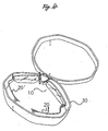
- Fig. 8 shows the spectacles (10) accommodated in a spectacle case (30).
- the spectacles (10) are flexed near the bridge center portion in such a manner that the lenses and the temple arms draw one arc.
- the spectacles (10) can be accommodated in such a manner that the lenses are inclined obliquely relative to the bottom surface of the case (30), whereby the accommodation can be more compact.
- the spectacles according to the present invention can be used by any person who needs the spectacles except for persons who take heavy exercise or persons who exist in a severe environment such as a strong wind.
- the spectacles according to the present invention are held on the face by four pads, the contact area of the spectacles to the skin is reduced, whereby the discomfort can be eased when the spectacles are put on. Furthermore, since two of the four pads are in contact with the pit regions of the temples at both the sides of the face, the spectacles can be easily surely held on the face. Moreover, since the length of the temple arms can be excessively shortened, compared to conventional spectacles, more compact lighter spectacles can be provided. Accordingly, since the discomfort and a sense of fatigue which a human being feels can be reduced, more specifically, the spectacles of the present invention is effective in doing a desk work and in watching a television, a movie or the like for a long time.
- the grips are disposed near the center portion of the lenses, whereby the grips are held between the fingers so that the spectacles can be carried.
- the force of the fingers is applied to or released from the grips, whereby the temple arms and the temple pads can be opened and closed. Accordingly, it is not necessary to take the spectacles out of the case, to open both the temple arms, to grasp the temple arms and to carry earpieces above the ears.
- the spectacles according to the present invention can be simply held between the fingers. That is to say, the grips are held between the fingers so as to take the spectacles out of the case, and the force is simply applied to the grips, whereby the spectacles can be put on. Accordingly, a person having one disabled hand can easily put on the spectacles without any trouble.
Landscapes
- Physics & Mathematics (AREA)
- Health & Medical Sciences (AREA)
- General Physics & Mathematics (AREA)
- Ophthalmology & Optometry (AREA)
- Optics & Photonics (AREA)
- Eyeglasses (AREA)
- Lasers (AREA)
- Materials For Medical Uses (AREA)
Claims (3)
- Brille, umfassend eine Brücke (14), die eine Elastizität zum Verbinden von zwei Linsen miteinander aufweist, und zwei Bügel-bzw. Bügelarme (20, 20'), die die Elastizität besitzen, wobei sich jeder von den Linsen erstreckt, wobei die Brücke (14) aus einem Metalldrahtmaterial besteht, das Federcharakteristik besitzt und die Bügelarme (20, 20') ein Metalldrahtmaterial umfassen, das eine Federcharakteristik aufweist und weiters umfassend: zwei Nasenkissen (18, 18'), wobei die Nasenkissen zueinander durch die Federcharakteristik der Brücke vorgespannt sind, so daß, wenn die Brille getragen wird, die Nasenkissen beide Seiten eine Nase des Trägers drücken; und zwei Bügelkissen (24, 24'), die an jedem der zwei Bügelarme (20, 20') zum Drücken auf Vertiefungsbereiche der Schläfen eines Trägers auf beiden Seiten einer Stirn bzw. eines Stimschädels des Trägers montiert sind, wodurch die vier Kissen (18, 18', 24, 24') die Brille auf dem Gesicht halten.
- Brille nach Anspruch 1, weiters umfassend zwei Griffe (16, 16'), wobei die Griffe (16, 16') mit der Brücke (14) assoziiert sind und adaptiert sind, um zwischen Fingern gehalten zu werden; so daß in Benutzung, wenn auf die zwei Griffe (16, 16') gedrückt wird, die Brücke (14) mit dem Zentrum der Brücke (14) als ein Support so gebogen ist bzw. wird, daß die Abstände zwischen den zwei Bügelarmen (20, 20') und zwischen den zwei Bügelkissen (24, 24') beabstandet werden können; und so daß, wenn die Druckkraft auf die Griffe (16, 16') freigegeben ist, die Griffe (16, 16') dorthin, wo sie waren, mittels einer elastischen Kraft der Brücke (14) zurückkehren können.
- Brille nach Anspruch 1, wobei die Nasenkissen (18, 18') und die Bügelkissen (24, 24') ein Silikonmaterial umfassen.
Applications Claiming Priority (1)
| Application Number | Priority Date | Filing Date | Title |
|---|---|---|---|
| PCT/JP1997/001186 WO1998045748A1 (fr) | 1997-04-07 | 1997-04-07 | Lunettes |
Publications (3)
| Publication Number | Publication Date |
|---|---|
| EP0907094A1 EP0907094A1 (de) | 1999-04-07 |
| EP0907094A4 EP0907094A4 (de) | 1999-12-29 |
| EP0907094B1 true EP0907094B1 (de) | 2005-12-28 |
Family
ID=14180381
Family Applications (1)
| Application Number | Title | Priority Date | Filing Date |
|---|---|---|---|
| EP97914621A Expired - Lifetime EP0907094B1 (de) | 1997-04-07 | 1997-04-07 | Brille |
Country Status (8)
| Country | Link |
|---|---|
| US (1) | US6135592A (de) |
| EP (1) | EP0907094B1 (de) |
| JP (1) | JP3156161B2 (de) |
| AT (1) | ATE314676T1 (de) |
| DE (1) | DE69734979T2 (de) |
| DK (1) | DK0907094T3 (de) |
| ES (1) | ES2255104T3 (de) |
| WO (1) | WO1998045748A1 (de) |
Cited By (1)
| Publication number | Priority date | Publication date | Assignee | Title |
|---|---|---|---|---|
| RU2707838C1 (ru) * | 2019-01-28 | 2019-11-29 | ООО "Оптика-Центр" | Углообразный мост очковой оправы |
Families Citing this family (18)
| Publication number | Priority date | Publication date | Assignee | Title |
|---|---|---|---|---|
| DE19832521A1 (de) * | 1998-07-20 | 2000-01-27 | Jose Joaquim Liesegang | Brillengestell |
| US5997137A (en) * | 1998-08-12 | 1999-12-07 | The Hilsinger Company Lp | Modular eyewear assembly |
| DE19958005C1 (de) * | 1999-12-02 | 2001-07-26 | Rainer Weber | Brille |
| GB0016218D0 (en) * | 2000-06-30 | 2000-08-23 | Noul Laudis | Frame-less,automatically folding lenses |
| US6719425B2 (en) * | 2002-03-15 | 2004-04-13 | Microvision Optical, Inc. | Ultra-light, hingeless plastic eyeglass frame |
| US6648471B1 (en) | 2002-09-10 | 2003-11-18 | David Dalrymple | Eyeglass frame |
| DE102008051498A1 (de) * | 2008-10-13 | 2010-06-24 | Hermann Thomas | Brillengestell mit Aufhängevorrichtung |
| KR101232408B1 (ko) * | 2008-10-27 | 2013-02-12 | 김영호 | 무테안경용 결합부 |
| JP5297292B2 (ja) * | 2009-07-30 | 2013-09-25 | 株式会社Nakamichi | 鼻掛け用眼鏡 |
| JP5052707B2 (ja) | 2010-06-15 | 2012-10-17 | 三菱電機株式会社 | 車両周辺監視装置 |
| HUE047190T2 (hu) * | 2013-09-18 | 2020-04-28 | Leung Yuet Charn | Moduláris szemüveg és ennek elõállítása |
| ITBO20130724A1 (it) * | 2013-12-31 | 2015-07-01 | Roberto Carlon | Occhiale, in particolare di tipo pieghevole. |
| JP6320194B2 (ja) * | 2014-06-23 | 2018-05-09 | 株式会社シャルマン | 眼鏡 |
| US9753306B2 (en) * | 2014-09-17 | 2017-09-05 | Marchon Eyewear, Inc. | Eyewear with flexible bridge |
| US9477095B1 (en) * | 2015-06-26 | 2016-10-25 | Charmant Co., Ltd. | Eyeglasses |
| WO2020033400A1 (en) * | 2018-08-07 | 2020-02-13 | Basora Thomas A J | Safety eyewear for reclining and supine positions |
| US12436408B2 (en) * | 2022-11-11 | 2025-10-07 | Htc Corporation | Wearable device |
| WO2026010694A1 (en) * | 2024-07-04 | 2026-01-08 | Bex Sunglasses, LLC | Interchangeable nose pad and tether system |
Family Cites Families (15)
| Publication number | Priority date | Publication date | Assignee | Title |
|---|---|---|---|---|
| GB191510241A (en) * | 1915-07-14 | 1916-06-08 | Hugo Brinkhaus | Improvements in or relating to Pince-nez. |
| US1533506A (en) * | 1923-03-12 | 1925-04-14 | William A Mann | Bow attachment for spectacles |
| US1914971A (en) * | 1929-09-04 | 1933-06-20 | William W Ferris | Lyeglass structure |
| FR1262034A (fr) * | 1960-04-15 | 1961-05-26 | Monture de lunettes perfectionnée | |
| FR1594831A (de) * | 1968-11-22 | 1970-06-08 | ||
| JPS6084918U (ja) * | 1983-11-15 | 1985-06-12 | 株式会社石田光器製作所 | メガネ |
| JPH0233215Y2 (de) * | 1985-05-14 | 1990-09-07 | ||
| JP2556117B2 (ja) * | 1988-11-08 | 1996-11-20 | 信越化学工業株式会社 | 眼鏡用部材 |
| JP2524388Y2 (ja) * | 1989-06-12 | 1997-01-29 | 関東特殊製鋼 株式会社 | めがねフレーム |
| JPH0343625U (de) * | 1989-09-07 | 1991-04-24 | ||
| WO1994020876A1 (en) * | 1993-03-05 | 1994-09-15 | Cvi/Beta Ventures, Inc. | An eyeglass frame with polymeric encapsulated shape-memory alloy components |
| EP0663605A1 (de) * | 1994-01-12 | 1995-07-19 | Aristo International Corporation | Brille mit eingegossenen Gläsern und Brücke |
| IT1280836B1 (it) * | 1995-03-31 | 1998-02-11 | Pietro Devercelli | Montatura per occhiali con un ponte intermedio tra le lenti perfezionato. |
| JP3022722U (ja) * | 1995-09-18 | 1996-04-02 | 株式会社フクオカラシ | 高フィッティング眼鏡フレーム |
| JP3022723U (ja) * | 1995-09-18 | 1996-04-02 | 株式会社フクオカラシ | バネ式ブリッジを備えた眼鏡フレーム |
-
1997
- 1997-04-07 EP EP97914621A patent/EP0907094B1/de not_active Expired - Lifetime
- 1997-04-07 JP JP52587597A patent/JP3156161B2/ja not_active Expired - Fee Related
- 1997-04-07 US US09/202,042 patent/US6135592A/en not_active Expired - Lifetime
- 1997-04-07 AT AT97914621T patent/ATE314676T1/de not_active IP Right Cessation
- 1997-04-07 ES ES97914621T patent/ES2255104T3/es not_active Expired - Lifetime
- 1997-04-07 DK DK97914621T patent/DK0907094T3/da active
- 1997-04-07 WO PCT/JP1997/001186 patent/WO1998045748A1/ja not_active Ceased
- 1997-04-07 DE DE69734979T patent/DE69734979T2/de not_active Expired - Fee Related
Cited By (1)
| Publication number | Priority date | Publication date | Assignee | Title |
|---|---|---|---|---|
| RU2707838C1 (ru) * | 2019-01-28 | 2019-11-29 | ООО "Оптика-Центр" | Углообразный мост очковой оправы |
Also Published As
| Publication number | Publication date |
|---|---|
| JP3156161B2 (ja) | 2001-04-16 |
| WO1998045748A1 (fr) | 1998-10-15 |
| DE69734979T2 (de) | 2006-08-17 |
| US6135592A (en) | 2000-10-24 |
| ES2255104T3 (es) | 2006-06-16 |
| DE69734979D1 (de) | 2006-02-02 |
| EP0907094A4 (de) | 1999-12-29 |
| EP0907094A1 (de) | 1999-04-07 |
| DK0907094T3 (da) | 2006-05-15 |
| ATE314676T1 (de) | 2006-01-15 |
Similar Documents
| Publication | Publication Date | Title |
|---|---|---|
| EP0907094B1 (de) | Brille | |
| US4129362A (en) | Eyeglasses | |
| TWI297086B (en) | Eyewear with replaceable lens | |
| JP2983950B2 (ja) | 着脱可能な保護シールドを有する眼鏡 | |
| US8820921B1 (en) | Assembly for retaining eyeglasses on the head of a user in multiple positions | |
| US6745396B1 (en) | Articulating support arm apparatus for head-worn devices | |
| JPH10513279A (ja) | 眼鏡用テンプル | |
| US4840476A (en) | Compact eyeglass construction | |
| JPWO1998045748A1 (ja) | 眼 鏡 | |
| US6490757B2 (en) | Articulating hinge assembly for head-worn devices | |
| CN1125004A (zh) | 眼镜的双重眼镜腿系统 | |
| EP0385002A1 (de) | Brille | |
| US6036310A (en) | Eyeglasses with infinitely variable temple adjustment | |
| US20090040455A1 (en) | System and method for enhancing eyeglass positioning | |
| JPH04261513A (ja) | 眼鏡のつるの挾持装置 | |
| JP7386939B1 (ja) | コンタクトレンズ着用と分離のための開眼装置 | |
| JP6829515B2 (ja) | 眼鏡フレーム | |
| US20190155049A1 (en) | Reversible Eyeglass Frame | |
| US6746116B1 (en) | Multi-purpose glasses | |
| JP7038245B1 (ja) | テンプル部の多目的突起付き眼鏡 | |
| CN217718307U (zh) | 一种镜架及眼镜 | |
| US4141628A (en) | Eyeglasses temple construction | |
| JPS5977410A (ja) | 眼鏡用フレ−ム | |
| JP2003307712A (ja) | セミテンプル眼鏡 | |
| JP3020147U (ja) | 鼻メガネ |
Legal Events
| Date | Code | Title | Description |
|---|---|---|---|
| PUAI | Public reference made under article 153(3) epc to a published international application that has entered the european phase |
Free format text: ORIGINAL CODE: 0009012 |
|
| 17P | Request for examination filed |
Effective date: 19981202 |
|
| AK | Designated contracting states |
Kind code of ref document: A1 Designated state(s): AT BE CH DE DK ES FI FR GB GR IE IT LI LU MC NL PT SE |
|
| RIC1 | Information provided on ipc code assigned before grant |
Free format text: 6G 02C 5/00 A, 6G 02C 1/00 B, 6G 02C 5/06 B |
|
| A4 | Supplementary search report drawn up and despatched |
Effective date: 19991111 |
|
| AK | Designated contracting states |
Kind code of ref document: A4 Designated state(s): AT BE CH DE DK ES FI FR GB GR IE IT LI LU MC NL PT SE |
|
| 17Q | First examination report despatched |
Effective date: 20011019 |
|
| GRAP | Despatch of communication of intention to grant a patent |
Free format text: ORIGINAL CODE: EPIDOSNIGR1 |
|
| GRAS | Grant fee paid |
Free format text: ORIGINAL CODE: EPIDOSNIGR3 |
|
| GRAA | (expected) grant |
Free format text: ORIGINAL CODE: 0009210 |
|
| AK | Designated contracting states |
Kind code of ref document: B1 Designated state(s): AT BE CH DE DK ES FI FR GB GR IE IT LI LU MC NL PT SE |
|
| REG | Reference to a national code |
Ref country code: GB Ref legal event code: FG4D |
|
| REG | Reference to a national code |
Ref country code: CH Ref legal event code: EP |
|
| REG | Reference to a national code |
Ref country code: IE Ref legal event code: FG4D |
|
| REF | Corresponds to: |
Ref document number: 69734979 Country of ref document: DE Date of ref document: 20060202 Kind code of ref document: P |
|
| REG | Reference to a national code |
Ref country code: SE Ref legal event code: TRGR |
|
| REG | Reference to a national code |
Ref country code: CH Ref legal event code: NV Representative=s name: PATENTANWAELTE SCHAAD, BALASS, MENZL & PARTNER AG |
|
| PG25 | Lapsed in a contracting state [announced via postgrant information from national office to epo] |
Ref country code: IE Free format text: LAPSE BECAUSE OF NON-PAYMENT OF DUE FEES Effective date: 20060407 Ref country code: FI Free format text: LAPSE BECAUSE OF NON-PAYMENT OF DUE FEES Effective date: 20060407 Ref country code: AT Free format text: LAPSE BECAUSE OF NON-PAYMENT OF DUE FEES Effective date: 20060407 |
|
| PG25 | Lapsed in a contracting state [announced via postgrant information from national office to epo] |
Ref country code: ES Free format text: LAPSE BECAUSE OF NON-PAYMENT OF DUE FEES Effective date: 20060408 |
|
| PG25 | Lapsed in a contracting state [announced via postgrant information from national office to epo] |
Ref country code: MC Free format text: LAPSE BECAUSE OF NON-PAYMENT OF DUE FEES Effective date: 20060430 Ref country code: LI Free format text: LAPSE BECAUSE OF NON-PAYMENT OF DUE FEES Effective date: 20060430 Ref country code: CH Free format text: LAPSE BECAUSE OF NON-PAYMENT OF DUE FEES Effective date: 20060430 Ref country code: BE Free format text: LAPSE BECAUSE OF NON-PAYMENT OF DUE FEES Effective date: 20060430 |
|
| PG25 | Lapsed in a contracting state [announced via postgrant information from national office to epo] |
Ref country code: DK Free format text: LAPSE BECAUSE OF NON-PAYMENT OF DUE FEES Effective date: 20060501 |
|
| REG | Reference to a national code |
Ref country code: DK Ref legal event code: T3 |
|
| REG | Reference to a national code |
Ref country code: GR Ref legal event code: EP Ref document number: 20060400891 Country of ref document: GR |
|
| REG | Reference to a national code |
Ref country code: ES Ref legal event code: FG2A Ref document number: 2255104 Country of ref document: ES Kind code of ref document: T3 |
|
| ET | Fr: translation filed | ||
| PG25 | Lapsed in a contracting state [announced via postgrant information from national office to epo] |
Ref country code: NL Free format text: LAPSE BECAUSE OF NON-PAYMENT OF DUE FEES Effective date: 20061101 |
|
| PLBE | No opposition filed within time limit |
Free format text: ORIGINAL CODE: 0009261 |
|
| STAA | Information on the status of an ep patent application or granted ep patent |
Free format text: STATUS: NO OPPOSITION FILED WITHIN TIME LIMIT |
|
| REG | Reference to a national code |
Ref country code: DK Ref legal event code: EBP |
|
| 26N | No opposition filed |
Effective date: 20060929 |
|
| REG | Reference to a national code |
Ref country code: CH Ref legal event code: PL |
|
| NLV4 | Nl: lapsed or anulled due to non-payment of the annual fee |
Effective date: 20061101 |
|
| PG25 | Lapsed in a contracting state [announced via postgrant information from national office to epo] |
Ref country code: PT Free format text: LAPSE BECAUSE OF NON-PAYMENT OF DUE FEES Effective date: 20070108 |
|
| REG | Reference to a national code |
Ref country code: IE Ref legal event code: MM4A |
|
| REG | Reference to a national code |
Ref country code: PT Ref legal event code: MM4A Free format text: LAPSE DUE TO NON-PAYMENT OF FEES Effective date: 20070108 |
|
| REG | Reference to a national code |
Ref country code: FR Ref legal event code: ST Effective date: 20061230 |
|
| REG | Reference to a national code |
Ref country code: ES Ref legal event code: FD2A Effective date: 20060408 |
|
| BERE | Be: lapsed |
Owner name: *POLARIS INTER A.B. Effective date: 20060430 |
|
| PG25 | Lapsed in a contracting state [announced via postgrant information from national office to epo] |
Ref country code: GR Free format text: LAPSE BECAUSE OF NON-PAYMENT OF DUE FEES Effective date: 20060329 Ref country code: FR Free format text: LAPSE BECAUSE OF NON-PAYMENT OF DUE FEES Effective date: 20060502 |
|
| PG25 | Lapsed in a contracting state [announced via postgrant information from national office to epo] |
Ref country code: LU Free format text: LAPSE BECAUSE OF NON-PAYMENT OF DUE FEES Effective date: 20060407 |
|
| PGFP | Annual fee paid to national office [announced via postgrant information from national office to epo] |
Ref country code: SE Payment date: 20090407 Year of fee payment: 13 Ref country code: DE Payment date: 20090409 Year of fee payment: 13 |
|
| PGFP | Annual fee paid to national office [announced via postgrant information from national office to epo] |
Ref country code: GB Payment date: 20090408 Year of fee payment: 13 |
|
| EUG | Se: european patent has lapsed | ||
| GBPC | Gb: european patent ceased through non-payment of renewal fee |
Effective date: 20100407 |
|
| PG25 | Lapsed in a contracting state [announced via postgrant information from national office to epo] |
Ref country code: DE Free format text: LAPSE BECAUSE OF NON-PAYMENT OF DUE FEES Effective date: 20101103 |
|
| PG25 | Lapsed in a contracting state [announced via postgrant information from national office to epo] |
Ref country code: GB Free format text: LAPSE BECAUSE OF NON-PAYMENT OF DUE FEES Effective date: 20100407 |
|
| PGFP | Annual fee paid to national office [announced via postgrant information from national office to epo] |
Ref country code: IT Payment date: 20110125 Year of fee payment: 11 |
|
| PGRI | Patent reinstated in contracting state [announced from national office to epo] |
Ref country code: IT Effective date: 20110501 |
|
| PG25 | Lapsed in a contracting state [announced via postgrant information from national office to epo] |
Ref country code: SE Free format text: LAPSE BECAUSE OF NON-PAYMENT OF DUE FEES Effective date: 20100408 |
|
| PG25 | Lapsed in a contracting state [announced via postgrant information from national office to epo] |
Ref country code: IT Free format text: LAPSE BECAUSE OF NON-PAYMENT OF DUE FEES Effective date: 20080407 |