EP0907083B1 - Automatische Handhabung von mit einer abschraubbaren Kappe verschlossenen Probenbehältern - Google Patents
Automatische Handhabung von mit einer abschraubbaren Kappe verschlossenen Probenbehältern Download PDFInfo
- Publication number
- EP0907083B1 EP0907083B1 EP98810932A EP98810932A EP0907083B1 EP 0907083 B1 EP0907083 B1 EP 0907083B1 EP 98810932 A EP98810932 A EP 98810932A EP 98810932 A EP98810932 A EP 98810932A EP 0907083 B1 EP0907083 B1 EP 0907083B1
- Authority
- EP
- European Patent Office
- Prior art keywords
- sample cup
- sample
- cap
- recess
- gripper
- Prior art date
- Legal status (The legal status is an assumption and is not a legal conclusion. Google has not performed a legal analysis and makes no representation as to the accuracy of the status listed.)
- Expired - Lifetime
Links
Images


Classifications
-
- G—PHYSICS
- G01—MEASURING; TESTING
- G01N—INVESTIGATING OR ANALYSING MATERIALS BY DETERMINING THEIR CHEMICAL OR PHYSICAL PROPERTIES
- G01N35/00—Automatic analysis not limited to methods or materials provided for in any single one of groups G01N1/00 - G01N33/00; Handling materials therefor
- G01N35/02—Automatic analysis not limited to methods or materials provided for in any single one of groups G01N1/00 - G01N33/00; Handling materials therefor using a plurality of sample containers moved by a conveyor system past one or more treatment or analysis stations
- G01N35/04—Details of the conveyor system
-
- B—PERFORMING OPERATIONS; TRANSPORTING
- B67—OPENING, CLOSING OR CLEANING BOTTLES, JARS OR SIMILAR CONTAINERS; LIQUID HANDLING
- B67B—APPLYING CLOSURE MEMBERS TO BOTTLES JARS, OR SIMILAR CONTAINERS; OPENING CLOSED CONTAINERS
- B67B7/00—Hand- or power-operated devices for opening closed containers
- B67B7/18—Hand- or power-operated devices for opening closed containers for removing threaded caps
- B67B7/182—Hand- or power-operated devices for opening closed containers for removing threaded caps power-operated
-
- G—PHYSICS
- G01—MEASURING; TESTING
- G01N—INVESTIGATING OR ANALYSING MATERIALS BY DETERMINING THEIR CHEMICAL OR PHYSICAL PROPERTIES
- G01N35/00—Automatic analysis not limited to methods or materials provided for in any single one of groups G01N1/00 - G01N33/00; Handling materials therefor
- G01N35/02—Automatic analysis not limited to methods or materials provided for in any single one of groups G01N1/00 - G01N33/00; Handling materials therefor using a plurality of sample containers moved by a conveyor system past one or more treatment or analysis stations
- G01N35/04—Details of the conveyor system
- G01N2035/0401—Sample carriers, cuvettes or reaction vessels
- G01N2035/0403—Sample carriers with closing or sealing means
- G01N2035/0405—Sample carriers with closing or sealing means manipulating closing or opening means, e.g. stoppers, screw caps, lids or covers
-
- G—PHYSICS
- G01—MEASURING; TESTING
- G01N—INVESTIGATING OR ANALYSING MATERIALS BY DETERMINING THEIR CHEMICAL OR PHYSICAL PROPERTIES
- G01N35/00—Automatic analysis not limited to methods or materials provided for in any single one of groups G01N1/00 - G01N33/00; Handling materials therefor
- G01N35/10—Devices for transferring samples or any liquids to, in, or from, the analysis apparatus, e.g. suction devices, injection devices
- G01N2035/1027—General features of the devices
- G01N2035/1048—General features of the devices using the transfer device for another function
- G01N2035/1051—General features of the devices using the transfer device for another function for transporting containers, e.g. retained by friction
-
- Y—GENERAL TAGGING OF NEW TECHNOLOGICAL DEVELOPMENTS; GENERAL TAGGING OF CROSS-SECTIONAL TECHNOLOGIES SPANNING OVER SEVERAL SECTIONS OF THE IPC; TECHNICAL SUBJECTS COVERED BY FORMER USPC CROSS-REFERENCE ART COLLECTIONS [XRACs] AND DIGESTS
- Y10—TECHNICAL SUBJECTS COVERED BY FORMER USPC
- Y10T—TECHNICAL SUBJECTS COVERED BY FORMER US CLASSIFICATION
- Y10T29/00—Metal working
- Y10T29/49—Method of mechanical manufacture
- Y10T29/49815—Disassembling
- Y10T29/49819—Disassembling with conveying of work or disassembled work part
-
- Y—GENERAL TAGGING OF NEW TECHNOLOGICAL DEVELOPMENTS; GENERAL TAGGING OF CROSS-SECTIONAL TECHNOLOGIES SPANNING OVER SEVERAL SECTIONS OF THE IPC; TECHNICAL SUBJECTS COVERED BY FORMER USPC CROSS-REFERENCE ART COLLECTIONS [XRACs] AND DIGESTS
- Y10—TECHNICAL SUBJECTS COVERED BY FORMER USPC
- Y10T—TECHNICAL SUBJECTS COVERED BY FORMER US CLASSIFICATION
- Y10T29/00—Metal working
- Y10T29/49—Method of mechanical manufacture
- Y10T29/49815—Disassembling
- Y10T29/49822—Disassembling by applying force
-
- Y—GENERAL TAGGING OF NEW TECHNOLOGICAL DEVELOPMENTS; GENERAL TAGGING OF CROSS-SECTIONAL TECHNOLOGIES SPANNING OVER SEVERAL SECTIONS OF THE IPC; TECHNICAL SUBJECTS COVERED BY FORMER USPC CROSS-REFERENCE ART COLLECTIONS [XRACs] AND DIGESTS
- Y10—TECHNICAL SUBJECTS COVERED BY FORMER USPC
- Y10T—TECHNICAL SUBJECTS COVERED BY FORMER US CLASSIFICATION
- Y10T29/00—Metal working
- Y10T29/53—Means to assemble or disassemble
- Y10T29/53313—Means to interrelatedly feed plural work parts from plural sources without manual intervention
- Y10T29/53322—Means to assemble container
-
- Y—GENERAL TAGGING OF NEW TECHNOLOGICAL DEVELOPMENTS; GENERAL TAGGING OF CROSS-SECTIONAL TECHNOLOGIES SPANNING OVER SEVERAL SECTIONS OF THE IPC; TECHNICAL SUBJECTS COVERED BY FORMER USPC CROSS-REFERENCE ART COLLECTIONS [XRACs] AND DIGESTS
- Y10—TECHNICAL SUBJECTS COVERED BY FORMER USPC
- Y10T—TECHNICAL SUBJECTS COVERED BY FORMER US CLASSIFICATION
- Y10T29/00—Metal working
- Y10T29/53—Means to assemble or disassemble
- Y10T29/53443—Means to assemble or disassemble container and fluid component
-
- Y—GENERAL TAGGING OF NEW TECHNOLOGICAL DEVELOPMENTS; GENERAL TAGGING OF CROSS-SECTIONAL TECHNOLOGIES SPANNING OVER SEVERAL SECTIONS OF THE IPC; TECHNICAL SUBJECTS COVERED BY FORMER USPC CROSS-REFERENCE ART COLLECTIONS [XRACs] AND DIGESTS
- Y10—TECHNICAL SUBJECTS COVERED BY FORMER USPC
- Y10T—TECHNICAL SUBJECTS COVERED BY FORMER US CLASSIFICATION
- Y10T29/00—Metal working
- Y10T29/53—Means to assemble or disassemble
- Y10T29/53687—Means to assemble or disassemble by rotation of work part
Definitions
- the invention concerns a sample cup according to the preamble of claim 1.
- the invention further concerns an apparatus according to the preamble of claim 2.
- the invention further concerns a method according to the preamble of claim 3.
- the invention concerns in particular a sample cup, an apparatus, and a method of the above mentioned types which are suitable in particular for isolating a nucleic acid sample from cell material.
- sample cups have to be hermetically closed preferably with a screwable cap in order to ensure that the sample contained therein cannot be contaminated by external agents and also in order to protect laboratory staff from the risk of being contaminated by a pathological sample which may be contained in the sample cup.
- the cap of such a sample cup has to be removed and replaced manually with great care in order to allow pipetting operations, e.g. for transferring a portion of a biological sample contained in a primary sample tube can be pipetted into the sample cup, e.g. before a method for isolating a nucleic acid sample from cell material is carried out on a sample contained in a sample cup, or for transferring a nucleic acid sample isolated by such a method into the sample cup.
- US Patent number US-A-5826400 discloses an apparatus and a method for bottle capping, a plurality of bottles with petaloid lobes on the bottom of the bottles being seated in nests with fingers inserted between the petaloid lobes of the bottles to prevent rotation of the bottle during rotation of the capping head when the caps are successively engaged and applied to the threaded necks of the bottles.
- UK Patent Application GB2187720A describes a method and an apparatus for automatic capping or uncapping screw closures onto or from containers.
- the containers are received in recesses around the periphery of a rotatable table.
- the recesses are vertically aligned with capping heads which move with the table. Rotation of the capping head whilst engaged with the closure causes to screw the closure onto the neck of the container.
- Part of the inner surface of the recesses is provided with a series of teeth angled backwardly in relation to the direction of rotation, the teeth frictionally engaging with the surface of the bottle neck as to resist rotation during capping.
- European Patent Application EP-A-676643 describes a system using several vessels which are closed by individual caps.
- This known system comprises means for automatically opening and closing the vessels by automatically removing and replacing the individual caps.
- each cap has a lower part which tightly fits into the open upper end of a vessel, and an upper part which has a cylindrical cavity for receiving an opening tool.
- the tool for automatically removing the caps is matched to the shape of the upper part of the cap.
- This tool has the shape of a tapered plug which has a removal ring which has to be pressed into the upper part of the cap over a corresponding resistance of the cap. When the tapered plug is withdraem the removal ring acts as a resistance.
- French Patent FR-A-2129254 describes an arrangement wherein jaws 17 grasp and held a screwable closure 15 and a container 11 is held by a rotatable gripper 13.
- Container has in its upper part a screw thread for connecting it to screwable closure 15.
- screwable closure 15 is held by jaws 17 and container 11 is held and rotated by gripper 13.
- a first aim of the invention is therefore to provide a sample cup which is suitable for satisfying the above mentioned needs in the most simple and therefore less expensive way.
- a second aim of the invention is to provide an apparatus and a method which are suitable for satisfying the above mentioned needs in the most simple and therefore less expensive way.
- the aims of the invention are attained with a sample cup according to claim 1.
- the aims of the invention are attained with an apparatus according to claim 2.
- the aims of the invention are attained with a method according to claim 3.
- the main advantage of the sample cup, apparatus and method according to the invention is that they provide very simple and relatively inexpensive means for automatically opening, closing and transporting sample cups.
- An apparatus comprises a transportable and rotatable the gripper 11 of the type described hereinafter with reference to Figures 1 to 3.
- Transport of gripper 11 is carried out e.g. by an X-Y-Z transport system which enables movement of gripper 11 in 3 directions which are normal to each other.
- Rotation of the gripper is carried out by suitable controlled motor means associated to the latter transport system.
- the controlled motor means are such that rotation of gripper 11 and thereby of gripper tool 21 is possible in both angular senses, clockwise or in the opposite sense.
- the controlled motor means include means for measuring variations of the amount of electrical energy associated to rotational movement of the gripper tool. In this way the apparatus is able to detect different states of its operation, e.g. when the gripper tool has engaged the recess of the cap 34 and force should be applied to unscrew cap 34 and remove it from sample cap 31.
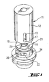
- Gripper 11 comprises a housing 12 having a top wall and a. side wall which has elongated openings 13 and 13 a (not shown) located on diametrically opposite sides of the side wall of housing 12, a first spring 14, and a gripper tool 21 which has a cylindrical upper part 16 which has a cavity 15 and a bottom wall connected to a shaft 25 which extends along the rotation axis of the cylindrical upper part 16 and has a lower end 24.
- Pin shaped projections 17 and 17 a radially extend in opposite directions from the side wall of cylindrical upper part 16.
- Shaft 25 has at its lower end pin shaped projections 22, 23 which radially extend in opposite directions.
- An annular disk 19 is free to glide along shaft 25 between the bottom wall of cylindrical upper part 16 and pin shaped projections 22, 23. Disk 19 is however pressed against projections 22, 23 by a second spring 18 arranged with respect to shaft 25 as shown by Fig. 2.
- spring 14 and cylindrical part 16 are so arranged within housing 12 that pin shaped projections 17 and 17 a pass through respective openings 13, 13 a of housing 12, and spring 14 transmits force exerted on it by housing 12 to cylindrical upper part 16. In this way depending on the magnitude of the force applied, cylindrical upper part 16 can move within housing 12 within limits defined by the length of openings 13, 13 a.
- gripper tool 21 rotates with it.
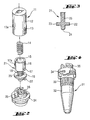
- Figures 1 and 2 show a cap 34 of a sample cup according to the invention.
- FIGS 4 to 7 show in more detail a sample cup 31 according to the invention.
- a sample cup 31 comprises a removable screwable cap 34 which has a recess located in the top and central part of the cap. This recess comprises a slot 37 which extends along the length axis of the sample cup 31 and which ends in two annular channel segments 35, 36 which extend in opposite angular directions with respect to the length axis of the sample cup 31.
- Sample cup 31 has an outer wall 32 which has a zone 33 the shape of which is adapted to cooperate with the shape of a corresponding zone of the inner surface of a chamber of a sample cup holder in order to prevent rotation of the sample cup 31 when the lower part thereof is inserted in that chamber.
- An essential feature of an apparatus according to the invention is that it comprises a rotatable gripper tool 21 which is configured and dimensioned to enter and engage with a recess 35, 36 of said cap 34 to form a connection which can be locked by rotating the gripper tool 21 in a first sense with respect to said sample cup 31 and which can be unlocked by rotating the gripper tool 21 with respect to said sample cup 31 in a second sense opposite to the first.
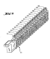
- an apparatus is used to handle a plurality of sample cups 51-69 each of which is inserted in one of a corresponding plurality of chambers of a sample cup holder 41 which has e.g. the shape shown by Fig. 8.
- the inner surface of each of said chambers has to have a zone the shape of which is apt to cooperate with zone 33 of the outer wall of sample cup 31 in such a way that when such a sample cup is inserted in one of the chambers of sample cup holder 41, sample cup 31 is held stationary by said chamber and is not free to rotate around its length axis.
- each of the sample cups 51-69 shown in Fig. 8 is closed with a removable screwable cap and the lower part of which is inserted in one of said chambers of the sample cup holder 41.
- the outer wall of each of said cups 51-69 has a zone which cooperates with a corresponding zone of the inner surface of the chamber of the sample cup holder 41 to prevent rotation of the sample cup 51-69 inserted in said chamber.
- each of sample cups 51-69 has a recess located in the top and central part of the cap, said recess comprising a slot which extends along the length axis of the sample cup and which ends in two annular channel segments which extend in opposite angular directions with respect to the length axis of the sample cup.
- An apparatus according to the invention for the above mentioned use with reference to Fig. 8 comprises a gripper of the type described above with reference to Figures 1-3, that is a gripper like gripper 11 movable in three orthogonal directions by a transport device.
- a gripper comprises a rotatable gripper tool which has an end part having a shape and dimensions which match the shape and dimensions of the recess of the cap of each sample cup in such a way that the end part of the gripper tool can enter through the slot of the cap's recess and by rotation enter into and engage the annular channel segments of said recess.
- the transport device for moving the latter gripper is suitable for moving it in said three orthogonal directions, and for positioning and rotating the gripper tool of the gripper of a predetermined angle within the recess of the cap of each of the sample cups 51-69.
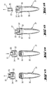
- Such a method comprises transporting a sample cup 31 by means of a transportable and rotatable gripper which includes a gripper tool 21 apt to enter a recess 35, 36, 37 of said cap 34, said transporting being effected by positioning said gripper tool 21 in said recess 35, 36, 37; by rotating said gripper tool 21 within said recess 35, 36, 37 with respect to said sample cup 31 until it engages and locks into said recess 35, 36, 37; and by transporting the gripper tool and thereby the sample cup 31 from a first position to a second position.
- gripper tool 21 In order to position gripper tool in the recess of cap 34, gripper tool 21 is lowered by the transport means (see Fig. 9) until it contacts the upper surface of cap 34. When that contact is established gripper tool 21 is rotated by the above mentioned controlled motor means while the transport means still exert a gentle downwards force on gripper tool 21. In this way, when the angular position of projections 22, 23 of gripper tool 21 coincides with the angular position of slot 37 of cap 34, the latter projections enter slot 37 and upon further rotation projections 22, 23 engage with annular channel segments 35, 36 of cap 34 (see Fig. 10), and in this way establish a locked connection between gripper tool 21 and cap 34, and thereby between gripper tool 21 and sample cup 31.
- Figures 11 and 12 illustrate upward and downward transport of sample cup 31 by means of gripper tool 21.
- a method for removing the screwable sample cap 34 of a sample cup 31 with an apparatus according to the invention is now described with reference to Figure 13.
- Such a method comprises positioning said gripper tool 21 in said recess 35, 36, 37 and rotating said gripper tool 21 within said recess 35, 36, 37 in a first sense with respect to said sample cup 31, thereby unscrewing the cap 34 and removing it from the sample cup 31.
- a method for replacing, i.e. for screwing a screwable sample cap 34 on a sample cup 31 with an apparatus according to the invention is now described with reference to Figures 14 and 15.
- Such a method comprises positioning said gripper tool 21 in said recess 35, 36, 37 and rotating said gripper tool 21 within said recess 35, 36, 37 in a second sense with respect to said sample cup 31, said second sense being opposite to said first sense, thereby screwing the cap 34 and replacing it on the sample cup 31.
- Figure 16 illustrates how cap 34 and thereby sample cup 31 is released from gripper tool 21.
Landscapes
- Immunology (AREA)
- Engineering & Computer Science (AREA)
- Life Sciences & Earth Sciences (AREA)
- Pathology (AREA)
- Analytical Chemistry (AREA)
- Biochemistry (AREA)
- General Health & Medical Sciences (AREA)
- General Physics & Mathematics (AREA)
- Health & Medical Sciences (AREA)
- Physics & Mathematics (AREA)
- Chemical & Material Sciences (AREA)
- Mechanical Engineering (AREA)
- Automatic Analysis And Handling Materials Therefor (AREA)
- Sampling And Sample Adjustment (AREA)
- Apparatus Associated With Microorganisms And Enzymes (AREA)
- Investigating Or Analysing Biological Materials (AREA)
- Centrifugal Separators (AREA)
- Devices For Use In Laboratory Experiments (AREA)
- Closures For Containers (AREA)
Claims (3)
- Probenbehälter (31) mit einer Längsachse und einer abschraubbaren Kappe (34) mit einer Ausnehmung, die in dem oberen Teil und in dem zentralen Teil der Kappe angeordnet ist, wobei der Probenbehälter eine äußere Wand (32) mit einem Bereich (33) hat, der geeignet ist, um mit einem korrespondierenden Bereich einer inneren Oberfläche einer Kammer eines Probenbehälterträgers zusammenzuwirken, um eine Drehung des Probenbehälters (31) zu verhindern, wenn sein unterer Teil in die Kammer eingebracht ist,
dadurch gekennzeichnet, dass
die Ausnehmung eine Nut (37) aufweist, die sich entlang der Längsachse des Probenbehälters (31) erstreckt und in zwei ringförmigen Kanalsegmenten (35,36) endet, die sich in entgegengesetzte Winkelrichtungen in Bezug auf die Längsachse des Probenbehälters (31) erstrecken. - Vorrichtung zur automatischen Handhabung von Probenbehältern in einem System, in dem Teile biologischer Proben, die in Primärprobenröhren enthalten sind, automatisch in die Probenbehälter und aus den Probenbehältern pippetiert werden müssen, weiter umfassenda) einen Probenbehälterträger (41) mit einer Vielzahl von Kammern, von denen jede geeignet ist, den unteren Teil eines Probenbehälters (51-69) aufzunehmen und drehfest zu halten,
dadurch gekennzeichnet, dass die Vorrichtung umfasstb) eine Vielzahl von Probenbehältern (51-61) nach Anspruch 1, von denen jeder mit einer abschraubbaren Kappe (34) geschlossen ist und deren unterer Teil jeweils in eine der Kammern des Probenbehälterträgers (41) eingesetzt ist,
wobei die äußere Wand jedes der Behälter (51-69) einen Bereich aufweist, dessen Form geeignet ist, um mit einem korrespondierenden Bereich der inneren Oberfläche der Kammer des Probenbehälterträgers (41) zusammenzuwirken, um eine Drehung des in die Kammer eingesetzten Probenbehälters (51-69) zu verhindern,c) einen Greifer (11), der von einer Transportvorrichtung in drei orthogonale Richtungen bewegbar ist, und ein drehbares Greifwerkzeug (21) aufweist, das an einem Endteil eine Form und Abmessungen aufweist, die mit der Form und den Abmessungen der Ausnehmung der Kappe derart zusammenpassen, dass das Endteil des Greifwerkzeugs (21) durch die Nut der Ausnehmung der Kappe gelangt und durch Drehung in die ringförmigen Kanalsegmente der Ausnehmung hineingelangt und eingreift,d) eine Transportvorrichtung zum Bewegen des Greifers (11) in die drei orthogonalen Richtungen und zum Positionieren und Drehen des Greifwerkzeugs (21) in einem vorbestimmten Winkel innerhalb der Ausnehmung der Kappe eines Probenbehälters (51-69). - Verfahren zur automatischen Handhabung von Probenbehältern, von denen jeder eine Längsachse hat und mit einer schraubbaren Kappe (34) geschlossen ist, in einem System, in dem Teile biologischer Proben, die in Primärprobenröhren enthalten sind, automatisch in und aus den Probenbehältern pippetiert werden müssen,
wobei die schraubbare Kappe eine Ausnehmung hat, die in dem oberen Teil und dem zentralen Teil der Kappe angeordnet ist, und die Ausnehmung eine Nut (37) aufweist, die sich entlang der Längsachse des Probenbehälters erstreckt,
dadurch gekennzeichnet, dass
die Nut in zwei ringförmigen Kanalsegmenten (35,36) endet, die sich in entgegengesetzte Winkelrichtungen in Bezug auf die Längsachse des Probenbehälters erstrecken,
und dadurch, dass das Verfahren weiter umfasst
Transportieren eines Probenbehälters (31) mittels eines transportablen Greifers (11), der ein drehbares Greifwerkzeug (21) einschließt, das geeignet ist, in die Ausnehmung (35,36,37) der Kappe (34) zu gelangen, wobei das Transportieren durch Positionieren des Greifwerkzeugs (21) in der Ausnehmung (35,36,37) erfolgt, indem das Greifwerkzeug (21) innerhalb der Ausnehmung (35,36,37) in Bezug auf den Probenbehälter (31) gedreht wird, bis es in die Ausnehmung (35,36,37) eingreift und verrastet, und der Greifer (11) und damit der Probenbehälter (31) von einer ersten Position in eine zweite Position transportiert werden.
Priority Applications (1)
| Application Number | Priority Date | Filing Date | Title |
|---|---|---|---|
| EP98810932A EP0907083B1 (de) | 1997-10-02 | 1998-09-18 | Automatische Handhabung von mit einer abschraubbaren Kappe verschlossenen Probenbehältern |
Applications Claiming Priority (3)
| Application Number | Priority Date | Filing Date | Title |
|---|---|---|---|
| EP97117102 | 1997-10-02 | ||
| EP97117102 | 1997-10-02 | ||
| EP98810932A EP0907083B1 (de) | 1997-10-02 | 1998-09-18 | Automatische Handhabung von mit einer abschraubbaren Kappe verschlossenen Probenbehältern |
Publications (2)
| Publication Number | Publication Date |
|---|---|
| EP0907083A1 EP0907083A1 (de) | 1999-04-07 |
| EP0907083B1 true EP0907083B1 (de) | 2006-07-26 |
Family
ID=8227429
Family Applications (1)
| Application Number | Title | Priority Date | Filing Date |
|---|---|---|---|
| EP98810932A Expired - Lifetime EP0907083B1 (de) | 1997-10-02 | 1998-09-18 | Automatische Handhabung von mit einer abschraubbaren Kappe verschlossenen Probenbehältern |
Country Status (8)
| Country | Link |
|---|---|
| US (2) | US6216340B1 (de) |
| EP (1) | EP0907083B1 (de) |
| JP (1) | JP4007700B2 (de) |
| AT (1) | ATE334396T1 (de) |
| CA (1) | CA2247589C (de) |
| DE (1) | DE69835325T2 (de) |
| DK (1) | DK0907083T3 (de) |
| ES (1) | ES2268760T3 (de) |
Families Citing this family (65)
| Publication number | Priority date | Publication date | Assignee | Title |
|---|---|---|---|---|
| CA2247589C (en) * | 1997-10-02 | 2007-01-09 | F. Hoffmann-La Roche Ag | Automatic handling of sample cups closed with a screwable cap |
| DE19926937A1 (de) * | 1999-06-14 | 2001-01-04 | Biopsytec Gmbh | Vorrichtung zur Aufnahme von Labor Reaktionsgefäßen |
| FR2804510B1 (fr) * | 2000-01-28 | 2003-02-07 | Biomerieux Sa | Cuvettes, appareil d'analyse biologique automatise utilisant de telles cuvettes, moyen de transfert de cuvettes dans un tel appareil et procede de transfert |
| ATE265264T1 (de) * | 2000-07-18 | 2004-05-15 | Basf Ag | Verfahren und vorrichtung zur automatisierten herstellung und charakterisierung von flüssigen mehrkomponentensystemen |
| DE10034890A1 (de) | 2000-07-18 | 2002-01-31 | Basf Ag | Vorrichtung und Verfahren zur automatisierten Formulierung und automatisierten Charakterisierung von Dispersionen |
| ITMI20010691A1 (it) * | 2001-03-30 | 2002-09-30 | Ronchi Mario S R L | Dispositivo di aggancio/sgancio rapido di gruppi di applicazione di tappi a contenitori |
| JP3911589B2 (ja) * | 2002-04-01 | 2007-05-09 | 東洋ゴム工業株式会社 | 液体封入式防振マウントの部品組込および液体封入装置 |
| EP1361441A1 (de) * | 2002-05-10 | 2003-11-12 | F. Hoffmann-La Roche Ag | Verfahren und Vorrichtung zum Transportieren einer Vielzahl von Probenröhrchen in einem Messsystem |
| EP1419820A1 (de) * | 2002-11-14 | 2004-05-19 | F. Hoffmann-La Roche Ag | Verfahren, Vorrichtung und Reaktionbehälter zur Bearbeitung von biologischen Proben |
| DE10308362A1 (de) * | 2003-02-27 | 2004-09-09 | Roche Diagnostics Gmbh | System zum automatischen Öffnen von Reagenzgefäßen |
| DE20310332U1 (de) * | 2003-07-04 | 2004-11-11 | Mwg-Biotech Ag | Vorrichtung zum automatischen Öffnen und Schließen von Reaktionsgefäßen |
| US7846395B2 (en) * | 2003-07-16 | 2010-12-07 | Ortho-Clinical Diagnostics, Inc. | Container closure and device to install and remove closure |
| TWM249914U (en) * | 2003-12-17 | 2004-11-11 | Exon Science Inc | Fast opening/closing gate for biochemical facility |
| WO2005110600A2 (en) * | 2004-05-18 | 2005-11-24 | Nunc A/S | Tube, cap and rack for automatic handling of samples |
| EP2415524A2 (de) | 2005-03-30 | 2012-02-08 | F. Hoffmann-La Roche AG | Abgedichtete Vorrichtung |
| EP1882949B1 (de) * | 2006-07-26 | 2010-01-20 | The Automation Partnership (Cambridge) Limited | Vorrichtung zum automatischen Verschliessen und Öffnen von Probenröhrchen |
| WO2008067844A1 (en) * | 2006-12-04 | 2008-06-12 | Inpeco Ip Ltd. | Apparatus for removing caps from tubular containers |
| EP2125224A4 (de) * | 2007-02-21 | 2014-07-09 | William Brewer | Pipettenspitzen für extraktion, probenentnahe und probenreinigung sowie verfahren zu ihrer verwendung |
| US8703492B2 (en) | 2007-04-06 | 2014-04-22 | Qiagen Gaithersburg, Inc. | Open platform hybrid manual-automated sample processing system |
| US7985375B2 (en) * | 2007-04-06 | 2011-07-26 | Qiagen Gaithersburg, Inc. | Sample preparation system and method for processing clinical specimens |
| DE102007028429A1 (de) * | 2007-06-20 | 2008-12-24 | Krones Ag | Vorrichtung zum Verschließen von Behältern mit Schraubverschlüssen |
| EP2031407B1 (de) | 2007-08-29 | 2012-06-06 | F. Hoffmann-La Roche AG | Kappenentnahmesystem |
| RU2479836C2 (ru) * | 2007-11-30 | 2013-04-20 | Икс-Рей Оптикал Системс, Инк. | Предварительно покрытые пленкой ячейки точного дозирования для рентгеноструктурного анализатора |
| US20110017651A1 (en) * | 2008-01-10 | 2011-01-27 | Ide Technologies Ltd. | Vertical desalination element |
| DE102008023550B4 (de) * | 2008-05-14 | 2012-12-27 | Dirk Peters | Multifunktionseinheit zum Entnehmen und Bearbeiten von Gefäßen mit Schraubdeckel |
| DE102008062080A1 (de) * | 2008-12-12 | 2010-06-17 | Karlsruher Institut für Technologie | Vorrichtung zum Transport atmosphärenempfindlicher Proben und Verwendung derselben |
| EP2287621A1 (de) | 2009-08-19 | 2011-02-23 | Roche Diagnostics GmbH | Reagenzkit für eine Analysiervorrichtung |
| US9108832B2 (en) * | 2009-11-04 | 2015-08-18 | Hitachi High Technologies Corporation | Cover opener and automatic analyzing device using same |
| US9953141B2 (en) | 2009-11-18 | 2018-04-24 | Becton, Dickinson And Company | Laboratory central control unit method and system |
| DE102010000743A1 (de) * | 2010-01-08 | 2011-07-14 | Hamilton Bonaduz Ag | Probenbehälter |
| US8196375B2 (en) | 2010-05-27 | 2012-06-12 | Matrix Technologies Corporation | Handheld tube capper/decapper |
| JP5417353B2 (ja) * | 2011-01-31 | 2014-02-12 | 株式会社日立ハイテクノロジーズ | 自動分析システム |
| FI20116059A7 (fi) * | 2011-10-28 | 2013-04-29 | Thermo Fisher Scientific Oy | Reagenssipullo, järjestelmä, menetelmä ja laite suljinkorkkien ja vastaavien käsittelemiseksi |
| US9381524B2 (en) | 2011-11-08 | 2016-07-05 | Becton, Dickinson And Company | System and method for automated sample preparation |
| US9075039B2 (en) | 2011-11-08 | 2015-07-07 | Becton, Dickinson And Company | Container and cap for a biological specimen |
| EP2882677B1 (de) * | 2012-08-07 | 2018-12-26 | Cedrex A/S | Vorrichtung und verfahren zum schliessen und öffnen von prüfröhrchen |
| AU2013202778A1 (en) | 2013-03-14 | 2014-10-02 | Gen-Probe Incorporated | Systems, methods, and apparatuses for performing automated reagent-based assays |
| AU2013202805B2 (en) | 2013-03-14 | 2015-07-16 | Gen-Probe Incorporated | System and method for extending the capabilities of a diagnostic analyzer |
| CA2907824C (en) * | 2013-04-09 | 2021-05-04 | Qiagen Gmbh | Closing arrangement and method of closing tube |
| EP2886508B1 (de) * | 2013-12-20 | 2016-04-13 | CTC Analytics AG | Betätigungsvorrichtung für Schraubdeckel |
| US10493457B2 (en) | 2014-03-28 | 2019-12-03 | Brooks Automation, Inc. | Sample storage and retrieval system |
| DE102014108299B4 (de) * | 2014-06-12 | 2023-04-27 | Airbus Operations Gmbh | Vorrichtung und Verfahren zur Positionserfassung einer beweglichen Transporteinheit |
| EP2982439B1 (de) * | 2014-08-06 | 2017-10-11 | Yantai AusBio Laboratories Co., Ltd. | Reagenzträgereinheit mit Kopplungseinheit zur Pipettenarmkopplung und deren Anwendungen |
| CN104476488B (zh) * | 2014-11-11 | 2016-04-27 | 重庆颐洋企业发展有限公司 | 滤芯筒体的锁紧方法 |
| CN104526645B (zh) * | 2014-11-11 | 2016-03-23 | 重庆颐洋企业发展有限公司 | 筒体锁紧方法 |
| JP6399200B2 (ja) * | 2015-02-16 | 2018-10-03 | 株式会社島津製作所 | 試料気化ユニット及びガスクロマトグラフ |
| JP6662389B2 (ja) * | 2015-12-07 | 2020-03-11 | 株式会社島津製作所 | 開口封止構造体、試料気化ユニット及びガスクロマトグラフ |
| JP6540521B2 (ja) * | 2016-01-15 | 2019-07-10 | 株式会社島津製作所 | 部材連結機構 |
| CN107904833B (zh) * | 2017-12-20 | 2023-08-25 | 南通亿思特机器人科技有限公司 | 一种染纱胶管处理设备 |
| PL238611B1 (pl) * | 2018-02-01 | 2021-09-13 | Tomasz Janiak | Trzpień obrotowy do otwierania i zamykania nakrętek fiolek laboratoryjnych |
| IT201800009973A1 (it) * | 2018-10-31 | 2020-05-01 | Mbf Spa | Gruppo di trasmissione moto per teste tappatrici per tappi a vite e macchina tappatrice dotata di tale gruppo di trasmissione moto |
| EP3894869B1 (de) * | 2018-12-14 | 2022-08-24 | Project Management Limited | Prüfröhrchenmanipulationsvorrichtung |
| CN110550589B (zh) * | 2019-09-05 | 2022-04-05 | 北京埃索特核电子机械有限公司 | 一种样品瓶自动开合盖系统 |
| CN115335706A (zh) | 2020-03-20 | 2022-11-11 | 基础科学公司 | 用于直线运动的具有磁耦合的自动取样器轨道系统 |
| US12320821B2 (en) | 2020-03-20 | 2025-06-03 | Elemental Scientific, Inc. | Autosampler system with automated sample container cover removal and sample probe positioning |
| CN111607501A (zh) * | 2020-06-05 | 2020-09-01 | 重庆工商大学 | 一种蔬菜叶片微生物采集装置 |
| WO2022026265A1 (en) * | 2020-07-28 | 2022-02-03 | Elemental Scientific, Inc. | Autosampler system with automated sample container cover removal and sample probe positioning |
| CN113682643A (zh) * | 2021-07-15 | 2021-11-23 | 中国海洋石油集团有限公司 | 一种易拆卸防冲击管端保护帽 |
| KR20230041850A (ko) | 2021-09-17 | 2023-03-27 | 삼성전자주식회사 | 밀폐 구조체 및 이를 포함하는 물질 보유 장치 |
| CN113998301A (zh) * | 2021-09-30 | 2022-02-01 | 泰普生物科学(中国)有限公司 | 一种瓶盖组件 |
| CN113866067B (zh) * | 2021-10-27 | 2025-03-11 | 济南兰光机电技术有限公司 | 一种透湿杯旋紧装置、旋紧仪及旋紧方法 |
| CN114088963A (zh) * | 2021-11-29 | 2022-02-25 | 倍仪昇智能科技(苏州)有限公司 | 高通量病毒检测前处理系统及前处理方法 |
| CN114217086B (zh) * | 2022-02-22 | 2022-05-13 | 江苏睿玻生物科技有限公司 | 生物样本的自动分装系统及方法、脱帽组件、可读介质 |
| CN117817328B (zh) * | 2023-12-11 | 2025-12-09 | 江苏远闻科技有限公司 | 一种离心管全自动化装配装置 |
| CN117773844A (zh) * | 2024-01-10 | 2024-03-29 | 中国石油化工股份有限公司 | 一种拧盖工具 |
Citations (3)
| Publication number | Priority date | Publication date | Assignee | Title |
|---|---|---|---|---|
| FR2129254A5 (en) * | 1971-03-19 | 1972-10-27 | Commissariat Energie Atomique | Remote operated wrench mechanism - for screw capped isotope containers used in calorimetry |
| GB2187720A (en) * | 1986-03-11 | 1987-09-16 | Metal Box Plc | Capping or uncapping containers |
| US5826400A (en) * | 1996-08-21 | 1998-10-27 | Anderson-Martin Machine Company | Plastic bottle rotation restraint for capping machine |
Family Cites Families (14)
| Publication number | Priority date | Publication date | Assignee | Title |
|---|---|---|---|---|
| US2847139A (en) * | 1954-08-19 | 1958-08-12 | Christiansson Bror Gunnar | Screw cap |
| US3830390A (en) * | 1972-03-22 | 1974-08-20 | Sunbeam Plastics Corp | Safety closure for medicine bottles or the like |
| US3906706A (en) * | 1973-12-13 | 1975-09-23 | Dairy Cap Corp | Cap-tightener |
| US3955341A (en) * | 1975-10-14 | 1976-05-11 | Horix Manufacturing Company | Apparatus for screwing caps on containers |
| US4799599A (en) * | 1982-07-30 | 1989-01-24 | Ciba Corning Diagnostics Corp. | Specimen cup and cap assembly for clinical analyzer |
| US4984698A (en) * | 1988-01-26 | 1991-01-15 | Stuckey William C | Lockable closure cap |
| JP2522078B2 (ja) * | 1990-01-30 | 1996-08-07 | 株式会社島津製作所 | キャップ開閉装置 |
| US5366896A (en) * | 1991-07-30 | 1994-11-22 | University Of Virginia Alumni Patents Foundation | Robotically operated laboratory system |
| US5578494A (en) * | 1992-03-27 | 1996-11-26 | Abbott Laboratories | Cap actuator for opening and closing a container |
| GB9226153D0 (en) * | 1992-12-15 | 1993-02-10 | Canyon Europ Ltd | Closure caps for containers |
| FR2711243B1 (fr) * | 1993-10-14 | 1995-12-29 | Cogema | Ensemble de prélèvement d'échantillons liquides dans des cruchons obturés par des bouchons vissés. |
| DE4412286A1 (de) * | 1994-04-09 | 1995-10-12 | Boehringer Mannheim Gmbh | System zur kontaminationsfreien Bearbeitung von Reaktionsabläufen |
| US5464109A (en) * | 1994-08-15 | 1995-11-07 | Greenwald; Kenneth | Lockable bottle cap retainer |
| CA2247589C (en) * | 1997-10-02 | 2007-01-09 | F. Hoffmann-La Roche Ag | Automatic handling of sample cups closed with a screwable cap |
-
1998
- 1998-09-16 CA CA002247589A patent/CA2247589C/en not_active Expired - Fee Related
- 1998-09-18 ES ES98810932T patent/ES2268760T3/es not_active Expired - Lifetime
- 1998-09-18 AT AT98810932T patent/ATE334396T1/de active
- 1998-09-18 DE DE69835325T patent/DE69835325T2/de not_active Expired - Lifetime
- 1998-09-18 EP EP98810932A patent/EP0907083B1/de not_active Expired - Lifetime
- 1998-09-18 DK DK98810932T patent/DK0907083T3/da active
- 1998-09-29 US US09/162,550 patent/US6216340B1/en not_active Expired - Lifetime
- 1998-10-01 JP JP28000898A patent/JP4007700B2/ja not_active Expired - Lifetime
-
2001
- 2001-04-12 US US09/834,063 patent/US6651305B2/en not_active Expired - Lifetime
Patent Citations (3)
| Publication number | Priority date | Publication date | Assignee | Title |
|---|---|---|---|---|
| FR2129254A5 (en) * | 1971-03-19 | 1972-10-27 | Commissariat Energie Atomique | Remote operated wrench mechanism - for screw capped isotope containers used in calorimetry |
| GB2187720A (en) * | 1986-03-11 | 1987-09-16 | Metal Box Plc | Capping or uncapping containers |
| US5826400A (en) * | 1996-08-21 | 1998-10-27 | Anderson-Martin Machine Company | Plastic bottle rotation restraint for capping machine |
Also Published As
| Publication number | Publication date |
|---|---|
| ATE334396T1 (de) | 2006-08-15 |
| CA2247589C (en) | 2007-01-09 |
| DE69835325D1 (de) | 2006-09-07 |
| US20010013169A1 (en) | 2001-08-16 |
| US6216340B1 (en) | 2001-04-17 |
| JP4007700B2 (ja) | 2007-11-14 |
| CA2247589A1 (en) | 1999-04-02 |
| JPH11166933A (ja) | 1999-06-22 |
| EP0907083A1 (de) | 1999-04-07 |
| DE69835325T2 (de) | 2007-09-20 |
| ES2268760T3 (es) | 2007-03-16 |
| US6651305B2 (en) | 2003-11-25 |
| DK0907083T3 (da) | 2006-11-20 |
Similar Documents
| Publication | Publication Date | Title |
|---|---|---|
| EP0907083B1 (de) | Automatische Handhabung von mit einer abschraubbaren Kappe verschlossenen Probenbehältern | |
| EP2031407B1 (de) | Kappenentnahmesystem | |
| EP1452869B1 (de) | Vorrichtung zum automatischen Öffnen von Reagenzbehältern | |
| EP2390223B1 (de) | Tragbarer Verschlusskappenaufsetzer/-abnehmer | |
| EP3236267B1 (de) | Entstopfer und vorrichtung | |
| KR102369640B1 (ko) | 패키징 및 자동화 시스템에서 스크류탑 용기에 접근하기 위한 장치 | |
| HK1126277B (zh) | 去盖系统 | |
| HK1126277A (en) | Decapping system | |
| IES20190209A2 (en) | A test tube manipulation system |
Legal Events
| Date | Code | Title | Description |
|---|---|---|---|
| PUAI | Public reference made under article 153(3) epc to a published international application that has entered the european phase |
Free format text: ORIGINAL CODE: 0009012 |
|
| AK | Designated contracting states |
Kind code of ref document: A1 Designated state(s): AT BE CH DE DK ES FR GB IT LI NL |
|
| AX | Request for extension of the european patent |
Free format text: AL;LT;LV;MK;RO;SI |
|
| 17P | Request for examination filed |
Effective date: 19990615 |
|
| AKX | Designation fees paid |
Free format text: AT BE CH DE DK ES FR GB IT LI NL |
|
| GRAP | Despatch of communication of intention to grant a patent |
Free format text: ORIGINAL CODE: EPIDOSNIGR1 |
|
| GRAS | Grant fee paid |
Free format text: ORIGINAL CODE: EPIDOSNIGR3 |
|
| GRAA | (expected) grant |
Free format text: ORIGINAL CODE: 0009210 |
|
| AK | Designated contracting states |
Kind code of ref document: B1 Designated state(s): AT BE CH DE DK ES FR GB IT LI NL |
|
| REG | Reference to a national code |
Ref country code: GB Ref legal event code: FG4D |
|
| REG | Reference to a national code |
Ref country code: CH Ref legal event code: EP |
|
| REF | Corresponds to: |
Ref document number: 69835325 Country of ref document: DE Date of ref document: 20060907 Kind code of ref document: P |
|
| REG | Reference to a national code |
Ref country code: CH Ref legal event code: NV Representative=s name: VENTOCILLA PATENT AG |
|
| REG | Reference to a national code |
Ref country code: DK Ref legal event code: T3 |
|
| REG | Reference to a national code |
Ref country code: ES Ref legal event code: FG2A Ref document number: 2268760 Country of ref document: ES Kind code of ref document: T3 |
|
| PLBE | No opposition filed within time limit |
Free format text: ORIGINAL CODE: 0009261 |
|
| STAA | Information on the status of an ep patent application or granted ep patent |
Free format text: STATUS: NO OPPOSITION FILED WITHIN TIME LIMIT |
|
| 26N | No opposition filed |
Effective date: 20070427 |
|
| REG | Reference to a national code |
Ref country code: CH Ref legal event code: NV Representative=s name: ROCHE DIAGNOSTICS AG |
|
| PGFP | Annual fee paid to national office [announced via postgrant information from national office to epo] |
Ref country code: DK Payment date: 20110825 Year of fee payment: 14 |
|
| PGFP | Annual fee paid to national office [announced via postgrant information from national office to epo] |
Ref country code: AT Payment date: 20110825 Year of fee payment: 14 Ref country code: ES Payment date: 20110905 Year of fee payment: 14 |
|
| PGFP | Annual fee paid to national office [announced via postgrant information from national office to epo] |
Ref country code: NL Payment date: 20110912 Year of fee payment: 14 Ref country code: IT Payment date: 20110922 Year of fee payment: 14 |
|
| PGFP | Annual fee paid to national office [announced via postgrant information from national office to epo] |
Ref country code: BE Payment date: 20110927 Year of fee payment: 14 |
|
| REG | Reference to a national code |
Ref country code: CH Ref legal event code: PFA Owner name: F. HOFFMANN-LA ROCHE AG, CH Free format text: FORMER OWNER: F. HOFFMANN-LA ROCHE AG, CH |
|
| BERE | Be: lapsed |
Owner name: F. *HOFFMANN-LA ROCHE A.G. Effective date: 20120930 |
|
| REG | Reference to a national code |
Ref country code: NL Ref legal event code: V1 Effective date: 20130401 |
|
| REG | Reference to a national code |
Ref country code: AT Ref legal event code: MM01 Ref document number: 334396 Country of ref document: AT Kind code of ref document: T Effective date: 20120918 |
|
| REG | Reference to a national code |
Ref country code: DK Ref legal event code: EBP |
|
| PG25 | Lapsed in a contracting state [announced via postgrant information from national office to epo] |
Ref country code: AT Free format text: LAPSE BECAUSE OF NON-PAYMENT OF DUE FEES Effective date: 20120918 Ref country code: BE Free format text: LAPSE BECAUSE OF NON-PAYMENT OF DUE FEES Effective date: 20120930 |
|
| PG25 | Lapsed in a contracting state [announced via postgrant information from national office to epo] |
Ref country code: IT Free format text: LAPSE BECAUSE OF NON-PAYMENT OF DUE FEES Effective date: 20120918 Ref country code: NL Free format text: LAPSE BECAUSE OF NON-PAYMENT OF DUE FEES Effective date: 20130401 |
|
| REG | Reference to a national code |
Ref country code: ES Ref legal event code: FD2A Effective date: 20131021 |
|
| PG25 | Lapsed in a contracting state [announced via postgrant information from national office to epo] |
Ref country code: ES Free format text: LAPSE BECAUSE OF NON-PAYMENT OF DUE FEES Effective date: 20120919 Ref country code: DK Free format text: LAPSE BECAUSE OF NON-PAYMENT OF DUE FEES Effective date: 20121001 |
|
| REG | Reference to a national code |
Ref country code: FR Ref legal event code: PLFP Year of fee payment: 19 |
|
| REG | Reference to a national code |
Ref country code: FR Ref legal event code: PLFP Year of fee payment: 20 |
|
| PGFP | Annual fee paid to national office [announced via postgrant information from national office to epo] |
Ref country code: FR Payment date: 20170823 Year of fee payment: 20 Ref country code: GB Payment date: 20170829 Year of fee payment: 20 Ref country code: CH Payment date: 20170725 Year of fee payment: 20 |
|
| PGFP | Annual fee paid to national office [announced via postgrant information from national office to epo] |
Ref country code: DE Payment date: 20170928 Year of fee payment: 20 |
|
| REG | Reference to a national code |
Ref country code: DE Ref legal event code: R071 Ref document number: 69835325 Country of ref document: DE |
|
| REG | Reference to a national code |
Ref country code: CH Ref legal event code: PL |
|
| REG | Reference to a national code |
Ref country code: GB Ref legal event code: PE20 Expiry date: 20180917 |
|
| PG25 | Lapsed in a contracting state [announced via postgrant information from national office to epo] |
Ref country code: GB Free format text: LAPSE BECAUSE OF EXPIRATION OF PROTECTION Effective date: 20180917 |