EP0907061B1 - Wärmeübertrager für eine Heiz- oder Klimaanlage eines Kraftfahrzeuges - Google Patents
Wärmeübertrager für eine Heiz- oder Klimaanlage eines Kraftfahrzeuges Download PDFInfo
- Publication number
- EP0907061B1 EP0907061B1 EP98118368A EP98118368A EP0907061B1 EP 0907061 B1 EP0907061 B1 EP 0907061B1 EP 98118368 A EP98118368 A EP 98118368A EP 98118368 A EP98118368 A EP 98118368A EP 0907061 B1 EP0907061 B1 EP 0907061B1
- Authority
- EP
- European Patent Office
- Prior art keywords
- heat exchanger
- accordance
- pipes
- compartments
- air
- Prior art date
- Legal status (The legal status is an assumption and is not a legal conclusion. Google has not performed a legal analysis and makes no representation as to the accuracy of the status listed.)
- Expired - Lifetime
Links
- 238000004378 air conditioning Methods 0.000 title claims description 9
- 238000010438 heat treatment Methods 0.000 claims description 24
- 239000002826 coolant Substances 0.000 claims description 12
- 238000001125 extrusion Methods 0.000 claims description 9
- 239000004033 plastic Substances 0.000 claims description 3
- 229920003023 plastic Polymers 0.000 claims description 3
- 230000001105 regulatory effect Effects 0.000 claims 2
- 230000003014 reinforcing effect Effects 0.000 claims 1
- 238000004519 manufacturing process Methods 0.000 description 5
- 238000001816 cooling Methods 0.000 description 4
- 239000006260 foam Substances 0.000 description 3
- 239000002984 plastic foam Substances 0.000 description 3
- 238000010276 construction Methods 0.000 description 2
- 239000000498 cooling water Substances 0.000 description 2
- 239000003351 stiffener Substances 0.000 description 2
- 229910052782 aluminium Inorganic materials 0.000 description 1
- XAGFODPZIPBFFR-UHFFFAOYSA-N aluminium Chemical compound [Al] XAGFODPZIPBFFR-UHFFFAOYSA-N 0.000 description 1
- 230000009286 beneficial effect Effects 0.000 description 1
- 239000012267 brine Substances 0.000 description 1
- 239000004744 fabric Substances 0.000 description 1
- 238000009408 flooring Methods 0.000 description 1
- 238000009434 installation Methods 0.000 description 1
- 229910052751 metal Inorganic materials 0.000 description 1
- 239000002184 metal Substances 0.000 description 1
- 238000000034 method Methods 0.000 description 1
- HPALAKNZSZLMCH-UHFFFAOYSA-M sodium;chloride;hydrate Chemical compound O.[Na+].[Cl-] HPALAKNZSZLMCH-UHFFFAOYSA-M 0.000 description 1
Images


Classifications
-
- F—MECHANICAL ENGINEERING; LIGHTING; HEATING; WEAPONS; BLASTING
- F28—HEAT EXCHANGE IN GENERAL
- F28F—DETAILS OF HEAT-EXCHANGE AND HEAT-TRANSFER APPARATUS, OF GENERAL APPLICATION
- F28F3/00—Plate-like or laminated elements; Assemblies of plate-like or laminated elements
- F28F3/12—Elements constructed in the shape of a hollow panel, e.g. with channels
-
- B—PERFORMING OPERATIONS; TRANSPORTING
- B60—VEHICLES IN GENERAL
- B60H—ARRANGEMENTS OF HEATING, COOLING, VENTILATING OR OTHER AIR-TREATING DEVICES SPECIALLY ADAPTED FOR PASSENGER OR GOODS SPACES OF VEHICLES
- B60H1/00—Heating, cooling or ventilating [HVAC] devices
- B60H1/00321—Heat exchangers for air-conditioning devices
- B60H1/00328—Heat exchangers for air-conditioning devices of the liquid-air type
-
- F—MECHANICAL ENGINEERING; LIGHTING; HEATING; WEAPONS; BLASTING
- F28—HEAT EXCHANGE IN GENERAL
- F28D—HEAT-EXCHANGE APPARATUS, NOT PROVIDED FOR IN ANOTHER SUBCLASS, IN WHICH THE HEAT-EXCHANGE MEDIA DO NOT COME INTO DIRECT CONTACT
- F28D7/00—Heat-exchange apparatus having stationary tubular conduit assemblies for both heat-exchange media, the media being in contact with different sides of a conduit wall
- F28D7/10—Heat-exchange apparatus having stationary tubular conduit assemblies for both heat-exchange media, the media being in contact with different sides of a conduit wall the conduits being arranged one within the other, e.g. concentrically
- F28D7/106—Heat-exchange apparatus having stationary tubular conduit assemblies for both heat-exchange media, the media being in contact with different sides of a conduit wall the conduits being arranged one within the other, e.g. concentrically consisting of two coaxial conduits or modules of two coaxial conduits
-
- F—MECHANICAL ENGINEERING; LIGHTING; HEATING; WEAPONS; BLASTING
- F28—HEAT EXCHANGE IN GENERAL
- F28F—DETAILS OF HEAT-EXCHANGE AND HEAT-TRANSFER APPARATUS, OF GENERAL APPLICATION
- F28F1/00—Tubular elements; Assemblies of tubular elements
- F28F1/02—Tubular elements of cross-section which is non-circular
- F28F1/022—Tubular elements of cross-section which is non-circular with multiple channels
-
- F—MECHANICAL ENGINEERING; LIGHTING; HEATING; WEAPONS; BLASTING
- F28—HEAT EXCHANGE IN GENERAL
- F28F—DETAILS OF HEAT-EXCHANGE AND HEAT-TRANSFER APPARATUS, OF GENERAL APPLICATION
- F28F3/00—Plate-like or laminated elements; Assemblies of plate-like or laminated elements
- F28F3/02—Elements or assemblies thereof with means for increasing heat-transfer area, e.g. with fins, with recesses, with corrugations
- F28F3/04—Elements or assemblies thereof with means for increasing heat-transfer area, e.g. with fins, with recesses, with corrugations the means being integral with the element
-
- F—MECHANICAL ENGINEERING; LIGHTING; HEATING; WEAPONS; BLASTING
- F28—HEAT EXCHANGE IN GENERAL
- F28D—HEAT-EXCHANGE APPARATUS, NOT PROVIDED FOR IN ANOTHER SUBCLASS, IN WHICH THE HEAT-EXCHANGE MEDIA DO NOT COME INTO DIRECT CONTACT
- F28D21/00—Heat-exchange apparatus not covered by any of the groups F28D1/00 - F28D20/00
- F28D2021/0019—Other heat exchangers for particular applications; Heat exchange systems not otherwise provided for
- F28D2021/008—Other heat exchangers for particular applications; Heat exchange systems not otherwise provided for for vehicles
- F28D2021/0091—Radiators
- F28D2021/0092—Radiators with particular location on vehicle, e.g. under floor or on roof
Definitions
- the invention relates to a heat exchanger for a heating or Air conditioning system of a motor vehicle according to the features of independent patent claim 1.
- Heat exchangers of the type mentioned are known (Behr Air conditioners, brochure of Behr GmbH & Co., Stuttgart). In these heating or air conditioning systems for people and commercial vehicles is, as with the corresponding heating or Air conditioners from other manufacturers, always a central in known Way constructed of a finned tube block heat exchanger intended for the heating medium.
- the temperature to be tempered Air is supplied to the heat exchanger via a blower.
- the air to be tempered which may also be too Cooling purposes performed by an additional heat exchanger becomes, then through further flow channels to exhaust nozzles continued on the dashboard and below it, and distributed in the rear room are arranged. It will in addition, usually necessary for reasons of stability to arrange a support tube in the cockpit, so that thereby a very large space requirement in the vehicle, especially in the field of Center console, results.
- FR-A-2339830 discloses a method of manufacturing a heat exchanger.
- WO 93/17290 discloses a heat exchanger whose core is formed of modules is.
- the present invention has for its object to provide a heat exchanger for a heating or air conditioning of a motor vehicle in such a way that the Space requirements and the cost of the air duct kept much smaller can be.
- the heat exchanger becomes a unit with the necessary flow channels.
- the as supply and discharge lines serving pipes provide along with the rest Training of the profile also for the necessary stability.
- the profiles can be attached to the sides of them so bend the seated pipes in a relatively simple manner and relocate as desired.
- the tubes form also stiffeners and can by further, for example inserted pipes expanded to a rigid support structure his. This support structure can also be used as a load-bearing component, e.g. Serve in the area of the dashboard so that they part of the carrying skeleton are.
- the profile can be designed as an extruded profile his. But his production is also possible from two sheet metal shells and two layers of a corrugated fin sheet, the be soldered.
- the areas of the flat tube, in which the webs between the chambers are removed are, i. So the inflow and outflow areas as rectangular Triangles be formed, the catheters each of the openings of the associated pipe and of a closed Wall and the hypotenuse as one of the free ends of the Webs connecting straight line are formed.
- the inlet and the outlet area of the Mehrschachrohres each formed the same, but arranged so is that the respective associated final line parallel to each other. This way results namely the same flow length for the guide channels of the Mehrschachprofiles, so that in all places of same heat transfer can take place.
- the Flow channels for the air-forming ribs zigzagging have, so that the flow paths for the heat transfer get longer. It is known in the extrusion process, that you outside areas of an extruded profile corresponding transversely by corresponding moving parts deform to the extrusion direction and thereby a zigzag course can reach.
- the outer shell which covers the ribs, advantageously as a Plastic foam housing e.g. formed of EPP, which at the Outside can be beautifully designed.
- the new heat pipes can also be used immediately as insulating covering parts, for example for the Cockpit, but also for other areas of the interior, e.g. be formed in the rear room. In all cases it is too possible, the air flowing through the flow channels in countercurrent to heat or cool and the heat loss of the Inlet and outlet pipes are used to heat the air.
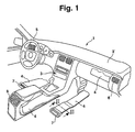
- Fig. 1 is a schematic part of the cockpit 1 with the running transversely under a windshield not shown in detail Dashboard 2 and a center console 3 shown and it can be seen that within the fitting stem 2 Flow channels 4, e.g. facing away from the steering wheel 5 Outlet nozzle 6 and more such flow channels 4 to the other unspecified exhaust nozzles in the area of Armature stem 2 and to discharge nozzles 7 and 8 in the area of the fondraumes are led.
- Flow channels 4 e.g. facing away from the steering wheel 5 Outlet nozzle 6 and more such flow channels 4 to the other unspecified exhaust nozzles in the area of Armature stem 2 and to discharge nozzles 7 and 8 in the area of the fondraumes are led.
- Fig. 2 shows that the flow channels 4 from one of the rest in Figs. 4 and 5 even closer extrusion shown 9, which consists essentially of a central flat tube 10 with several delimited by webs 11 from each other Chambers 12 exists, all in a common plane next to each other lie and run parallel to each other.
- the extrusion 9 is on the two laterally to each outermost chamber 12 adjacent edges with parallel to the chambers 12 extending tubes 13 and 14 are provided, the in the embodiment in one piece with the extruded profile 9 are formed.
- the tubes 13 and 14 project beyond the middle one Multi-chamber flat profile up to a height in the free outer edges of ribs 15 which ends on both sides of Flat chamber profile 10 protrude outwards.
- the ones of these Ribs 15 enclosed spaces 16 are of an outer jacket 17 covered, for example, from a plastic foam is formed of EPP and forms a housing whose Outside surfaces can be beautifully formed.
- the rooms 16 between the ribs 15 form flow channels for through the fan conveyed air, which then at the discharge nozzles. 6 or 7 or 8 can enter the vehicle interior.
- Fig. 6 shows that the ribs 15 ', here a have triangular cross-section, but also the Shape of the ribs 15 of FIG. 2 may have, together with the Tubes 13 and 14 of a shell 30 in the form of a network or cloth, of which only the left half is shown, surrounded are those that allow the heat exchanger to foam, without affecting the flow channels 16, or him in a insert prefabricated foam mold.
- the ribs 15 are at the production of the extruded profile 9 as running in a zigzag Ribs formed so that the flow channels 16 zigzagging.
- This embodiment is in the Production by extrusion by the arrangement movable Tool parts possible.
- the laterally arranged from the chambers 12 tubes 13 and 14th form stiffeners for the profile and can as support tubes serve for the construction, as exemplified in Figs. 7 and 8 is explained. They let themselves through at their ends extend plugged pipes to a suitable support structure.
- the tubes 13 and 14 are also used for supply and discharge the heating or cooling medium, i. So for the supply of heated engine cooling water for the purpose of heating or, if a cooling is required to supply one with a Cooling system in connection cooling medium (brine).
- connection cooling medium (brine).
- the Heating or cooling medium itself is from the tubes 13 and 14 in the chambers 12 out, as clearly with reference to FIG. 3 should be made.
- FIG. 3 shows that in the tube 13 a cap 18th and a similar end cap pressed into the tube 14 is, so that in each case a lead portion 19 to the open End of the respective tube 13 and 14 can be placed and so for example, heating medium only over the length l corresponding Part of the pipe 13 and discharged over the area 20 'and can be supplied via the supply line 19'.
- the Tubes 13 and 14 are for this purpose over the length 1 in the area 20 provided with slit-like openings 21.
- the new flow channels which can also be heat exchangers at the same time itself, in particular if the extruded aluminum has been prepared, relatively easily deform and thus adapt to the desired flow pattern.
- the Plastic cover 17 is also readily in certain Limits deformable. But it is also possible from the outset the plastic foam housing in the desired manner interpreted when the tubes 13 and 14, a stiffening and Exercise support function, as previously mentioned. So can the case e.g. be designed as a Bodenhell Faculty that between Body floor and carpet of the interior of a vehicle is arranged. It is also possible, the top of the Housing, if there are two parts of a top and bottom is constructed, between which arranged the heat exchanger is to conceal immediately with the flooring and the To let vehicle floor form. The top can also be formed as a cover shell of an instrument panel, whereby the lateral tubes at the same time the supporting structure form for at least part of the dashboard.
- the invention opens up a variety of uses for Air conditioning systems of motor vehicles.
- FIGS. 7 and 8 simulate the use of the heat exchangers the invention as part of the support structure clearly.
- Fig. 7 shows a heat exchanger, as in principle in 2 and 3 or 6 is shown, but with the difference that the tubes 13 'and 14' to the supply and discharge the heating or cooling medium, i. for feeding the heated Engine cooling water for the purpose of heating or even if one Cooling should be required to supply a cooling medium serve, not a round cross-section, but a rectangular, have in particular square cross-section.
- the rest of the embodiment does not deviate from that of FIGS. 2 and 3 from.
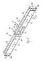
- FIG. 8 now shows that four heat exchangers 32, all in of the type shown in Fig. 7 are formed by connecting pipes 33 and end pieces 34 assembled to a cross member 35 who are with his two outer attachment ends 36 directly to the A-pillars of a motor vehicle can be attached.
- the carrier 35 therefore forms a supporting skeleton in the area of the dashboard, and it forms at the same time the basic framework for the arrangement of heat exchangers 32, used for heating and air conditioning of the vehicle interior can be used in the sense of FIG. 1.
- there the supply of heating or cooling medium takes place in each case Sense of the arrows 37 and the discharge in the sense of the arrows 38.
- the Tube parts 33 are not the heating or cooling medium flowed through and can be sealed accordingly.
- the to be tempered air is in the direction of arrows 31 through the Heat exchanger in a not shown in detail, centrally located Blower running, and then it can be tempered Condition sideways or upwards in the area of the dashboard escape.
- the support structure shown in FIG therefore uses the structure of the heat exchanger of stable Tubes 13 ', 14' in addition, by additional tubes 33 in addition to the heat exchanger also a supporting structure too form.
Landscapes
- Engineering & Computer Science (AREA)
- Physics & Mathematics (AREA)
- Thermal Sciences (AREA)
- Mechanical Engineering (AREA)
- General Engineering & Computer Science (AREA)
- Geometry (AREA)
- Air-Conditioning For Vehicles (AREA)
- Heat-Exchange Devices With Radiators And Conduit Assemblies (AREA)
Description
- Fig. 1
- die schematische perspektivische Ansicht eines Teiles des Innenraumes eines Personenkraftwagens, der mit Wärmeübertragern nach der Erfindung ausgerüstet ist,
- Fig. 2
- die vergrößerte Darstellung des Schnittes nach der Linie II-II in Fig. 1 durch einen der Wärmeübertrager nach der Erfindung,
- Fig. 3
- die Schnittdarstellung des Wärmeübertragers der Fig. 2 längs der Schnittlinie III-III in Fig. 2,
- Fig. 4
- die vergrößerte Darstellung des für den Wärmeübertrager der Fig. 1 bis 3 verwendeten Strangpreßprofiles,
- Fig. 5
- die Schnitt- bzw. Ansichtdarstellung einer Teillänge des Strangpreßprofiles der Fig. 4 in Richtung der Linie V-V der Fig. 4 gesehen,
- Fig. 6
- die perspektivische Teildarstellung des aus dem Profil der Fig. 4 gebildeten Wärmeübertragers vor der Umschäumung,
- Fig. 7
- einen Wärmeübertrager in einer anderen Ausführungsform, und
- Fig. 8
- Wärmeübertrager nach Fig. 7 als Teil einer Tragkonstruktion für ein Armaturenbrett.
Claims (15)
- Wärmeübertrager für eine Heiz- oder Klimaanlage eines Kraftfahrzeuges bestehend aus mehreren parallel zueinander verlaufenden, in Sammelkästen mündenden Führungskanälen für ein Heiz- oder Kühlmedium und aus mit den Außenflächen dieser Führungskanäle in Berührung stehenden Strömungskanälen für die zu temperierende Luft, wobei die Führungskanäle von mehreren durch Stege (11) voneinander getrennten und nebeneinander liegenden Kammern (12) eines Profils (9) in der Form eines Flachrohres gebildet sind, das angrenzend an die Kammern (12) mit nach außen abstehenden Rippen (15) versehen ist,
dadurch gekennzeichnet, daß die zwischen den Rippen bestehenden Räume (16) durch einen Außenmantel (17) als Strömungskanäle für die zu temperierende Luft ausgebildet sind,
und daß seitlich an die äußersten Kammern angrenzende Rohre (13, 14) als Zu- und Ablauf für das Heiz- oder Kühlmedium vorgesehen sind, die parallel zu den Kammern ausgerichtet sind und die auf einer vorbestimmten, als Sammelkasten dienenden Länge (1) mit Öffnungen (21) ausgerüstet sind, die in Bereiche (22) des Flachrohres (10) münden, in denen die Stege (11) zwischen den Kammern (12) entfernt sind. - Wärmeübertrager nach Anspruch 1, dadurch gekennzeichnet, daß die Öffnungen in den Rohren (13, 14) als Schlitze (21) ausgebildet sind.
- Wärmeübertrager nach Anspruch 1, dadurch gekennzeichnet, daß die Rohre (13, 14) als versteifende Tragrohre ausgebildet sind.
- Wärmeübertrager nach Anspruch 1, dadurch gekennzeichnet, daß die Rohre (13, 14) Teil des Profiles (9) sind.
- Wärmeübertrager nach einem der Ansprüche 1 bis 4, dadurch gekennzeichnet, daß das Profil ein Strangpreßprofil (9) ist.
- Wärmeübertrager nach Anspruch 1, dadurch gekennzeichnet, daß die Bereiche (22), die Teile der Sammelräume sind, die Form von rechtwinkligen Dreiecken aufweisen, wobei die Katheten von dem mit den Öffnungen (21) versehenen Teilen der Rohre (13, 14) und von einer geschlossenen Kante (24) des Strangpreßprofiles (11) und die Hyptenuse als eine die freien Enden (11a) der Stege (11) verbindende Gerade (23 bzw. 23') ausgebildet sind.
- Wärmeübertrager nach Anspruch 6, dadurch gekennzeichnet, daß die Geraden (23, 23') unter 45° zu den Längsachsen der Kammern (12) verlaufen.
- Wärmeübertrager nach Anspruch 6, dadurch gekennzeichnet, daß der Zu- und Ablaufbereich (22) jeweils gleich, aber so angeordnet ist, daß die Abschlußgeraden (23, 23') zueinander parallel verlaufen.
- Wärmeübertrager nach Anspruch 1, dadurch gekennzeichnet, daß die Rippen (15) zickzackförmig angeordnet sind.
- Wärmeübertrager nach Anspruch 1, dadurch gekennzeichnet, daß der Außenmantel von einem Kunststoffschaumgehäuse (17) gebildet ist.
- Wärmeübertrager nach Anspruch 10, dadurch gekennzeichnet, daß die Rippen (15, 15') und die Rohre (13, 14, 13', 14') von einer Hülle (30) umgeben sind, die innerhalb des Kunststoffschaumgehäuses liegt.
- Wärmeübertrager nach Anspruch 1, dadurch gekennzeichnet, daß der Außenmantel mit einem unmittelbar die Innenfläche eines Teilbereiches des Innenraumes eines Kraftfahrzeuges bildenden Belag kaschiert ist.
- Wärmeübertrager nach Anspruch 12, dadurch gekennzeichnet, daß der Außenmantel zweischalig ausgebildet ist und eine Schale die Deckschale der Instrumententafel bildet.
- Wärmeübertrager nach Anspruch 3, dadurch gekennzeichnet, daß die Rohre mit weiteren Rohren zu einem tragenden Skelett zusammengefügt sind, das als Tragteil in ein Fahrzeug eingesetzt ist.
- Verwendung eines Wärmeübertragers nach einem der Ansprüche 1 bis 14 für eine Klimaanlage eines Kraftfahrzeuges.
Applications Claiming Priority (2)
| Application Number | Priority Date | Filing Date | Title |
|---|---|---|---|
| DE19743426A DE19743426A1 (de) | 1997-10-01 | 1997-10-01 | Wärmeübertrager für eine Heiz- oder Klimaanlage eines Kraftfahrzeuges |
| DE19743426 | 1997-10-01 |
Publications (3)
| Publication Number | Publication Date |
|---|---|
| EP0907061A2 EP0907061A2 (de) | 1999-04-07 |
| EP0907061A3 EP0907061A3 (de) | 2000-05-03 |
| EP0907061B1 true EP0907061B1 (de) | 2004-05-26 |
Family
ID=7844305
Family Applications (1)
| Application Number | Title | Priority Date | Filing Date |
|---|---|---|---|
| EP98118368A Expired - Lifetime EP0907061B1 (de) | 1997-10-01 | 1998-09-29 | Wärmeübertrager für eine Heiz- oder Klimaanlage eines Kraftfahrzeuges |
Country Status (3)
| Country | Link |
|---|---|
| EP (1) | EP0907061B1 (de) |
| DE (2) | DE19743426A1 (de) |
| ES (1) | ES2219821T3 (de) |
Cited By (1)
| Publication number | Priority date | Publication date | Assignee | Title |
|---|---|---|---|---|
| DE102017200624A1 (de) | 2017-01-17 | 2018-07-19 | Bayerische Motoren Werke Aktiengesellschaft | Wärmetauschereinrichtung für ein Fahrzeug, insbesondere für ein Kraftfahrzeug, sowie Fahrzeug mit einer solchen Wärmetauschereinrichtung |
Families Citing this family (11)
| Publication number | Priority date | Publication date | Assignee | Title |
|---|---|---|---|---|
| ATE224309T1 (de) * | 2000-04-22 | 2002-10-15 | Benteler Werke Ag | Instrumententafelträger |
| US7011142B2 (en) | 2000-12-21 | 2006-03-14 | Dana Canada Corporation | Finned plate heat exchanger |
| CA2372399C (en) * | 2002-02-19 | 2010-10-26 | Long Manufacturing Ltd. | Low profile finned heat exchanger |
| CA2392610C (en) | 2002-07-05 | 2010-11-02 | Long Manufacturing Ltd. | Baffled surface cooled heat exchanger |
| FR2843448B1 (fr) * | 2002-08-08 | 2005-04-29 | Valeo Thermique Moteur Sa | Echangeur de chaleur plan, en particulier pour vehicule automobile, et procede pour sa fabrication |
| DE10305031A1 (de) * | 2003-02-07 | 2004-09-09 | F.W. Brökelmann Aluminiumwerk GmbH & Co. KG | Wärmeübertrager mit wabenförmigen Strömungsspalten |
| CA2425233C (en) | 2003-04-11 | 2011-11-15 | Dana Canada Corporation | Surface cooled finned plate heat exchanger |
| US7182125B2 (en) | 2003-11-28 | 2007-02-27 | Dana Canada Corporation | Low profile heat exchanger with notched turbulizer |
| WO2008058734A1 (de) * | 2006-11-15 | 2008-05-22 | Behr Gmbh & Co. Kg | Wärmeübertrager für kraftfahrzeug mit stranggepresstem gekrümmten strömungskanal |
| DE102008013450B4 (de) | 2008-03-10 | 2023-08-03 | Volkswagen Ag | Fahrgastraumklimatisierung in einem Fahrzeug und Wärmeaustauscher-Einrichtung dafür |
| CN103348209B (zh) * | 2011-02-14 | 2016-04-13 | 松下知识产权经营株式会社 | 热交换器及其制造方法 |
Family Cites Families (10)
| Publication number | Priority date | Publication date | Assignee | Title |
|---|---|---|---|---|
| US1887035A (en) * | 1930-04-16 | 1932-11-08 | Modine Mfg Co | Vehicle heater and heat control device |
| DE1023574B (de) * | 1954-02-01 | 1958-01-30 | Westermann & Co Gmbh M | Hohlplattenheizkoerper aus zwei am Rand miteinander verbundenen duennen Blechplatten |
| DE1551448B2 (de) * | 1967-02-17 | 1971-07-08 | Daimler Benz Ag, 7000 Stuttgart | Waermeaustauscher mit achsparallelen rohren, die rechteckige enden aufweisen |
| FR2339830A1 (fr) * | 1976-01-29 | 1977-08-26 | Alsthom Cgee | Procede de fabrication d'une plaque d'echange de chaleur |
| DE3516444A1 (de) * | 1984-07-05 | 1986-01-16 | Süddeutsche Kühlerfabrik Julius Fr. Behr GmbH & Co KG, 7000 Stuttgart | Waermetauscher fuer den einbau am fussboden oder in seitenwaenden eines kfz |
| DE3615300A1 (de) * | 1986-05-06 | 1987-11-12 | Norsk Hydro As | Kuehlrohre, sowie verfahren und vorrichtung zu deren herstellung |
| JPH0492166U (de) * | 1990-12-04 | 1992-08-11 | ||
| AU663168B2 (en) * | 1992-02-28 | 1995-09-28 | Milne Jurisich | Heat exchanger assembly |
| WO1994023257A1 (en) * | 1993-03-29 | 1994-10-13 | Melanesia International Trust Company Limited | Heat exchanger assembly |
| DE19519511A1 (de) * | 1994-05-31 | 1995-12-07 | Tjiok Mouw Ching | Wärmeaustauscher |
-
1997
- 1997-10-01 DE DE19743426A patent/DE19743426A1/de not_active Withdrawn
-
1998
- 1998-09-29 DE DE59811452T patent/DE59811452D1/de not_active Expired - Lifetime
- 1998-09-29 EP EP98118368A patent/EP0907061B1/de not_active Expired - Lifetime
- 1998-09-29 ES ES98118368T patent/ES2219821T3/es not_active Expired - Lifetime
Non-Patent Citations (1)
| Title |
|---|
| Prospekt der Firma Süddeutsche Kühlerfabrik Julius Fr. Behr GmbH & Co.Kg, Klima-Anlagen für Kraftfahrzeuge * |
Cited By (1)
| Publication number | Priority date | Publication date | Assignee | Title |
|---|---|---|---|---|
| DE102017200624A1 (de) | 2017-01-17 | 2018-07-19 | Bayerische Motoren Werke Aktiengesellschaft | Wärmetauschereinrichtung für ein Fahrzeug, insbesondere für ein Kraftfahrzeug, sowie Fahrzeug mit einer solchen Wärmetauschereinrichtung |
Also Published As
| Publication number | Publication date |
|---|---|
| DE59811452D1 (de) | 2004-07-01 |
| EP0907061A3 (de) | 2000-05-03 |
| ES2219821T3 (es) | 2004-12-01 |
| DE19743426A1 (de) | 1999-04-08 |
| EP0907061A2 (de) | 1999-04-07 |
Similar Documents
| Publication | Publication Date | Title |
|---|---|---|
| DE69301831T2 (de) | Armaturenbrett für ein kraftfahrzeug | |
| EP0907061B1 (de) | Wärmeübertrager für eine Heiz- oder Klimaanlage eines Kraftfahrzeuges | |
| EP1317356B1 (de) | Heiz- und gegebenenfalls klimagerät für nutzfahrzeuge, z.b. omnibusse | |
| DE4305060C2 (de) | Gelöteter Wärmetauscher, insbesondere Verdampfer | |
| DE3216877C1 (de) | In ein Gehaeuse einbaubares Waermeaustauschelement | |
| EP0901601B1 (de) | Wärmetauscher | |
| DE10120483A1 (de) | Anordnung zur Kühlung | |
| DE19711336A1 (de) | Bodenaufbau an einem Kraftfahrzeug-Heck | |
| DE102008024634A1 (de) | Wohnmobil oder Wohnwagen mit Warmluft-Thermoboden | |
| DE19804389B4 (de) | Klimaanlage mit Trennwand zur Unterteilung von Luftdurchlässen | |
| EP1228907A2 (de) | Klimagerät für ein Kraftfahrzeug | |
| EP1149717B1 (de) | Instrumententafelträger | |
| DE4332578C2 (de) | Kombinierte Warmluft- und Flächenheizung eines Omnibusses | |
| DE3012286A1 (de) | Waermetauscher | |
| DE3317982C1 (de) | Wärmetauscher, insbesondere für die Beheizung eines Fahrgastraumes von Personenkraftwagen | |
| DE3128906C2 (de) | ||
| DE102005019578A1 (de) | Vorrichtung zum Heizen durch Fluidzirkulation | |
| WO2005085737A1 (de) | Vorrichtung zum austausch von wärme und verfahren zur herstellung einer solchen vorrichtung | |
| DE3111360A1 (de) | Lueftungsvorrichtung fuer raeume mit zwei getrennten stroemungswegen zur be- und entlueftung | |
| DE112015003901B4 (de) | Sammelkammer für einen Wärmetauscher, Verbindungssystem und Wärmetauscher | |
| EP0599107A2 (de) | Heizkörper für ein Kraftfahrzeug | |
| DE19832051C2 (de) | Heiz- bzw. Kühlkörper-Verteileranordnung | |
| DE10234212A1 (de) | Flächenwärmeübertrager, insbesondere für Kraftfahrzeuge | |
| DE19839995C2 (de) | Kunststoff-Eisspeicherelement | |
| DE102015113544A1 (de) | Klimagerät |
Legal Events
| Date | Code | Title | Description |
|---|---|---|---|
| PUAI | Public reference made under article 153(3) epc to a published international application that has entered the european phase |
Free format text: ORIGINAL CODE: 0009012 |
|
| AK | Designated contracting states |
Kind code of ref document: A2 Designated state(s): DE ES FR GB |
|
| AX | Request for extension of the european patent |
Free format text: AL;LT;LV;MK;RO;SI |
|
| RIN1 | Information on inventor provided before grant (corrected) |
Inventor name: WOLF, WALTER, DIPL.-ING. Inventor name: STEMMLER, MARTIN, DR. RER. NAT. Inventor name: SCHMID, MARKUS, DIPL.-ING. Inventor name: LUZ, KLAUS, DIPL.-ING. Inventor name: DERLETH, MARTIN, DIPL.-ING. (FH) Inventor name: DAMSOHN, HERBERT, DR. ING. |
|
| PUAL | Search report despatched |
Free format text: ORIGINAL CODE: 0009013 |
|
| AK | Designated contracting states |
Kind code of ref document: A3 Designated state(s): AT BE CH CY DE DK ES FI FR GB GR IE IT LI LU MC NL PT SE |
|
| AX | Request for extension of the european patent |
Free format text: AL;LT;LV;MK;RO;SI |
|
| 17P | Request for examination filed |
Effective date: 20000823 |
|
| AKX | Designation fees paid |
Free format text: DE ES FR GB |
|
| 17Q | First examination report despatched |
Effective date: 20020429 |
|
| GRAP | Despatch of communication of intention to grant a patent |
Free format text: ORIGINAL CODE: EPIDOSNIGR1 |
|
| GRAS | Grant fee paid |
Free format text: ORIGINAL CODE: EPIDOSNIGR3 |
|
| GRAA | (expected) grant |
Free format text: ORIGINAL CODE: 0009210 |
|
| AK | Designated contracting states |
Kind code of ref document: B1 Designated state(s): DE ES FR GB |
|
| REG | Reference to a national code |
Ref country code: GB Ref legal event code: FG4D Free format text: NOT ENGLISH |
|
| REF | Corresponds to: |
Ref document number: 59811452 Country of ref document: DE Date of ref document: 20040701 Kind code of ref document: P |
|
| GBT | Gb: translation of ep patent filed (gb section 77(6)(a)/1977) |
Effective date: 20040805 |
|
| REG | Reference to a national code |
Ref country code: ES Ref legal event code: FG2A Ref document number: 2219821 Country of ref document: ES Kind code of ref document: T3 |
|
| RAP2 | Party data changed (patent owner data changed or rights of a patent transferred) |
Owner name: BEHR GMBH & CO. KG |
|
| ET | Fr: translation filed | ||
| PLBE | No opposition filed within time limit |
Free format text: ORIGINAL CODE: 0009261 |
|
| STAA | Information on the status of an ep patent application or granted ep patent |
Free format text: STATUS: NO OPPOSITION FILED WITHIN TIME LIMIT |
|
| 26N | No opposition filed |
Effective date: 20050301 |
|
| PGFP | Annual fee paid to national office [announced via postgrant information from national office to epo] |
Ref country code: GB Payment date: 20050822 Year of fee payment: 8 |
|
| GBPC | Gb: european patent ceased through non-payment of renewal fee |
Effective date: 20060929 |
|
| PGFP | Annual fee paid to national office [announced via postgrant information from national office to epo] |
Ref country code: ES Payment date: 20070926 Year of fee payment: 10 |
|
| PG25 | Lapsed in a contracting state [announced via postgrant information from national office to epo] |
Ref country code: GB Free format text: LAPSE BECAUSE OF NON-PAYMENT OF DUE FEES Effective date: 20060929 |
|
| PGFP | Annual fee paid to national office [announced via postgrant information from national office to epo] |
Ref country code: FR Payment date: 20070914 Year of fee payment: 10 |
|
| REG | Reference to a national code |
Ref country code: FR Ref legal event code: ST Effective date: 20090529 |
|
| PG25 | Lapsed in a contracting state [announced via postgrant information from national office to epo] |
Ref country code: FR Free format text: LAPSE BECAUSE OF NON-PAYMENT OF DUE FEES Effective date: 20080930 |
|
| REG | Reference to a national code |
Ref country code: ES Ref legal event code: FD2A Effective date: 20080930 |
|
| PG25 | Lapsed in a contracting state [announced via postgrant information from national office to epo] |
Ref country code: ES Free format text: LAPSE BECAUSE OF NON-PAYMENT OF DUE FEES Effective date: 20080930 |
|
| PGFP | Annual fee paid to national office [announced via postgrant information from national office to epo] |
Ref country code: DE Payment date: 20101025 Year of fee payment: 13 |
|
| REG | Reference to a national code |
Ref country code: DE Ref legal event code: R119 Ref document number: 59811452 Country of ref document: DE Effective date: 20120403 |
|
| PG25 | Lapsed in a contracting state [announced via postgrant information from national office to epo] |
Ref country code: DE Free format text: LAPSE BECAUSE OF NON-PAYMENT OF DUE FEES Effective date: 20120403 |