EP0904941B1 - Drucker für Aufzeichnungsträger sowie Farbbandkassette zur Verwendung in einem Drucker - Google Patents
Drucker für Aufzeichnungsträger sowie Farbbandkassette zur Verwendung in einem Drucker Download PDFInfo
- Publication number
- EP0904941B1 EP0904941B1 EP98115024A EP98115024A EP0904941B1 EP 0904941 B1 EP0904941 B1 EP 0904941B1 EP 98115024 A EP98115024 A EP 98115024A EP 98115024 A EP98115024 A EP 98115024A EP 0904941 B1 EP0904941 B1 EP 0904941B1
- Authority
- EP
- European Patent Office
- Prior art keywords
- ink ribbon
- section
- ribbon cassette
- ribbon
- pressure bar
- Prior art date
- Legal status (The legal status is an assumption and is not a legal conclusion. Google has not performed a legal analysis and makes no representation as to the accuracy of the status listed.)
- Expired - Lifetime
Links
- 239000011159 matrix material Substances 0.000 claims 5
- 230000032258 transport Effects 0.000 description 9
- 239000000428 dust Substances 0.000 description 6
- 238000011109 contamination Methods 0.000 description 2
- 229910052782 aluminium Inorganic materials 0.000 description 1
- XAGFODPZIPBFFR-UHFFFAOYSA-N aluminium Chemical compound [Al] XAGFODPZIPBFFR-UHFFFAOYSA-N 0.000 description 1
- 239000011248 coating agent Substances 0.000 description 1
- 238000000576 coating method Methods 0.000 description 1
- 239000000356 contaminant Substances 0.000 description 1
- 230000001419 dependent effect Effects 0.000 description 1
- 238000011161 development Methods 0.000 description 1
- 230000018109 developmental process Effects 0.000 description 1
- 239000003292 glue Substances 0.000 description 1
- 230000007257 malfunction Effects 0.000 description 1
- 229910052751 metal Inorganic materials 0.000 description 1
- 239000002184 metal Substances 0.000 description 1
- 238000000034 method Methods 0.000 description 1
Images

Classifications
-
- B—PERFORMING OPERATIONS; TRANSPORTING
- B41—PRINTING; LINING MACHINES; TYPEWRITERS; STAMPS
- B41J—TYPEWRITERS; SELECTIVE PRINTING MECHANISMS, i.e. MECHANISMS PRINTING OTHERWISE THAN FROM A FORME; CORRECTION OF TYPOGRAPHICAL ERRORS
- B41J32/00—Ink-ribbon cartridges
- B41J32/02—Ink-ribbon cartridges for endless ribbons
-
- B—PERFORMING OPERATIONS; TRANSPORTING
- B41—PRINTING; LINING MACHINES; TYPEWRITERS; STAMPS
- B41J—TYPEWRITERS; SELECTIVE PRINTING MECHANISMS, i.e. MECHANISMS PRINTING OTHERWISE THAN FROM A FORME; CORRECTION OF TYPOGRAPHICAL ERRORS
- B41J35/00—Other apparatus or arrangements associated with, or incorporated in, ink-ribbon mechanisms
- B41J35/04—Ink-ribbon guides
Definitions
- the invention relates to a printer for recording media, with one across the transport path of the record carrier extending pressure beam, with at least one approximately over the entire length of the pressure beam extending ribbon cassette for recording and Transporting an endless ribbon, the two on their opposite End arranged deflector has between which is a section of ribbon outside the cassette runs, and with a between the pressure bar and the Ribbon cassette arranged, parallel to the print bar Movable printing device that a needle printhead for Printing on the record carrier and a guide device has a portion of the ribbon section passes the needle printhead.
- a ribbon cartridge for use in a printer Such a printer and one usable therein Ribbon cartridges are known from US 3 977 512.
- a printer of the type mentioned is used for printing of recording media such as individual sheets of paper, Continuous paper webs or fanfold paper webs used.
- recording media such as individual sheets of paper, Continuous paper webs or fanfold paper webs used.
- the pressure bar is usually made of metal manufactured profile element, whose at the back of the Record carrier adjacent printing surface with a elastic coating is provided.
- the Printer a ribbon cartridge in which an ink soaked Continuous ribbon is recorded, with the ink of the Recording medium is printed.
- the well-known ribbon cassette usually spans the entire Length of the pressure beam and has the pressure beam on it facing front two at their opposite Deflection elements arranged at the ends, for example arms or rollers, between which a ribbon section of the Continuous ribbon is stretched outside the cassette.
- the Ribbon Within the ribbon is layered in a meandering pattern and passed through a device in which is soaked in ink.
- the Printer transports one with the drive of the printer coupled transport device on the ribbon cassette the ribbon continuously through the ribbon cartridge through it.
- Between the print bar and the ribbon cassette is also a movable parallel to the pressure bar Arranged printing device that a printhead like one Needle print head or a type wheel print head used to print on the record carrier. To do this by means of a guide device provided on the printing device a portion of the outside of the Ribbon cassette arranged ribbon section on Printhead passed.
- the individual needles or types of Printhead according to image data supplied to the printer the ribbon against the one against the pressure bar Record carrier.
- the invention has for its object a printer or to specify a ribbon cassette of the type mentioned at the outset, in which the ribbon is soiled is protected.
- This task is solved for a printer in that the ribbon section running outside the ribbon cassette seen from the pressure bar behind the needle print head lies, and that on the needle printhead a housing is provided for the guide device in which the Section of the ribbon section is guided and that one facing the pressure bar in front of the printing device Opening that has the section of the ribbon section released for printing. Furthermore, the task by an ink ribbon cassette with the features of the claim 9 solved. Advantageous further developments result itself from the dependent subclaims.
- the outside of the ribbon cassette running ribbon section with the greatest possible distance held to the print bar when the ribbon cassette is inserted in the printer. Dust that accumulates during the transport of the record carrier by the printer from the recording medium in the area of the pressure bar triggers, due to the large distance of the Ribbon section to the print bar only negligible to a small extent up to the ribbon section. At the same time, this prevents the printer from working on the printer provided housing a contamination of the near the pressure beam held in the guide device Section of the ribbon.
- the ribbon section To protect against pollution is at least one near the outside of the ribbon cartridge running ribbon section, arranged above the same Provide web that is parallel to the pressure beam runs and with one of its narrow sides to the pressure beam shows. Through this additional web, the area between the printing device and the ribbon cassette protected from paper dust despite the large Distance to the ribbon section. Further is it is possible to add another web below the ribbon section to provide.
- the web is rectangular in cross section, with its other narrow side on a pressure bar facing Front of the ribbon cassette attached and stands perpendicular from this. By attaching the web directly on the ribbon cassette, for example Glue or by integrating the web with the ribbon cassette is formed, the web is replaced with every replacement the ribbon cassette with replaced. Another It is possible to arrange the web in the printer in attaching the bar to the frame of the printer.
- the printer has the guide device on the side facing away from the pressure beam Back of the printing device two rotatably mounted Guide rollers and two on both sides of the needle print head arranged, pivotally mounted, in front of the needle print head arranged section of the ribbon section exciting wings.
- One of the two leadership roles directs the section of the ribbon section in the housing of the guide device.
- the other of the two guide rollers leads the section from the Casing.
- the use is rotatably mounted Guide rollers advantageous because the continuous ribbon underneath comparatively low tensile forces in the pressure device redirected and issued by this.
- To the To further increase the positional accuracy of the section is also proposed at the management facility additionally between each leadership role and that to provide a further guide role for the adjacent rocker.
- the ribbon becomes through these additional guide rollers defined held to the wings.
- Both the first Leadership roles as well as the other leadership roles can be cylindrical or barrel-shaped his.
- the Ribbon section with such a small distance to the Ribbon section facing the front of the ribbon cassette, that with the ribbon cartridge installed in the printer seen from the pressure bar behind the printing device lies, causing soiling of the continuous ribbon is prevented.
- the two deflection elements on the opposite Ends of the ribbon cartridge preferably on the the front facing the ribbon section rotatably mounted Pulleys.
- the axes of rotation of the pulleys run parallel in this preferred embodiment to the front of the ribbon cartridge and are vertical aligned to the longitudinal direction of the ribbon section. Due to the rotatable bearing of the pulleys and their symmetrical arrangement to the longitudinal direction of the ribbon section the continuous ribbon is comparatively exposed to low tensile forces, increasing the lifespan of the continuous ribbon is increased.
- pulleys can also be used, the rounded arms free ends parallel to the front of the ribbon cartridge and perpendicular to the longitudinal direction of the ribbon section run.
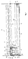
- FIGS. 1 and 2 show a printer 10 for printing of recording media such as single sheets of paper or continuous paper webs. For reasons of clarity are only components in FIGS. 1 and 2 of the printer 10, which is essential for the invention are.
- the printer 10 has a frame 12 that is only partially is shown, a transport device arranged in the frame 12 (not shown) and a controller (not shown).
- On frame 12 is made of aluminum manufactured pressure beam 14 attached, which is transverse to Direction of transport of the record carrier extends.
- the Pressure beam 14 is a hollow section with a rectangular cross section educated. There is one on its upper face inclined at an angle of about 5 ° to the pressure beam 14 Guide bar 16 formed in one piece, the Record carrier on the pressure bar 14 leads.
- Parallel to The pressure beam 14 on the frame 12 is round in cross section Guide 18 attached, along which a printing device 20 traversable across the transport path of the record carrier is.
- the printing device 20 has a print head carrier 22, the guide bushings 24 and 26 on the Guide 18 is slidably mounted.
- the print head carrier 22 has a carrier plate 28, on the top a needle print head 30 is attached centrally, the needle guide 32 faces the pressure bar 14.
- an ink ribbon cassette 34 Seen from the pressure bar 14 behind the printing device 20 is on the frame 12 by locking means (not shown) an ink ribbon cassette 34 is attached.
- the ribbon cartridge 34 runs parallel to the pressure beam 14 and extends over its entire length.
- an endless ink ribbon 36 is recorded, the one arranged in the ribbon cassette 34, from Printer 10 driven conveyor during printing (not shown) transported continuously becomes.
- the ribbon cassette has near each of its ends 34 each have a deflection roller 38 or 40, the Rotation axis parallel to the pressure surface of the pressure bar 14 and perpendicular to the direction of movement of the printing device 20 runs.
- the ribbon cassette 34 Immediately on each pulley 38 or 40, the ribbon cassette 34 has an opening 42 or 44, through which the continuous ribbon 36 from the ribbon cassette 34 is pulled or guided into this.
- the printing device 20 is also located a guide device 46 is provided, which is a section 36b of the ribbon section 36a on the needle guide 32 of the needle print head 30 passes.
- a guide device 46 is provided, which is a section 36b of the ribbon section 36a on the needle guide 32 of the needle print head 30 passes.
- the guide device 46 on the side facing away from the pressure beam 14
- two on the Carrier plate 28 rotatably mounted first guide rollers 48 and 50 and two arranged on both sides of the needle print head 30, on the support plate 28 pivotally mounted Swing 52 and 54.
- a second guide roller 56 and 58 is also arranged, which is also rotatable on the support plate 28 is stored.
- the printing device moves during the printing process 20 along the guide 18.
- the endless ribbon 36 continuously from that not shown Conveyor transported through the ribbon cassette 34.
- the first leadership roles enable 48 and 50 and the second guide rollers 56 and 58 a Relative movement between the continuous ribbon 36 and the Printing device 20.
- the printer 10 shown is a Printer type, which also includes continuous paper as a recording medium can print.
- continuous paper is for this purpose on the print head carrier 22 an additional knife wheel 59 rotatably mounted with a swiveling rail (not shown) can engage the paper to cut.
- the housing 60 surrounds a large part of the guide device 46 and the needle printhead 30.
- Front side 62 has the housing 60 immediately in front the needle printhead 30 an opening 64 that the portion 36b of the ribbon section 36a for printing releases.
- Through the housing 60 is in the guide device 46 guided section 36b of the ink-soaked Continuous ribbon 36 protected from paper dust, who transported himself past the pressure beam 14 Record carrier releases.
Landscapes
- Impression-Transfer Materials And Handling Thereof (AREA)
Description
- Fig. 1
- eine Draufsicht auf einen erfindungsgemäßen Drucker, und
- Fig. 2
- eine Seitenansicht des Druckers nach Fig. 1.
Claims (11)
- Drucker für Aufzeichnungsträger, mit einem quer zum Transportweg des Aufzeichnungsträgers verlaufenden Druckbalken (14), mit einer sich zumindest annähernd über die gesamte Länge des Druckbalkens (14) erstrekkenden Farbbandkassette (34) zur Aufnahme und zum Transport eines Endlosfarbbandes (36), die zwei an ihren entgegengesetzten Enden angeordnete Umlenkelemente (38 und 40) hat, zwischen denen ein Farbbandabschnitt (36a) außerhalb der Farbbandkassette (34) verläuft, und mit einer zwischen dem Druckbalken (14) und der Farbbandkassette (34) angeordneten, parallel zum Druckbalken (14) bewegbaren Druckeinrichtung (20), die einen Nadeldruckkopf (30) zum Bedrucken des Aufzeichnungsträgers und eine Führungseinrichtung (46) hat, die einen Teilabschnitt (36b) des Farbbandabschnittes (36a) am Nadeldruckkopf (30) vorbeiführt, dadurch gekennzeichnet, daß der außerhalb der Farbbandkassette (34) verlaufende Farbbandabschnitt (36a) vom Druckbalken (14) aus gesehen hinter der Druckeinrichtung (20), nahe der Farbbandkassette (34) liegt, und daß an der Druckeinrichtung (20) ein Gehäuse (60) für die Führungseinrichtung (46) vorgesehen ist, in dem der Teilabschnitt (36b) des Farbbandabschnittes (36a) geführt ist und das vor dem Nadeldruckkopf (30) eine dem Druckbalken (14) zugewandte Öffnung (64) hat, die den Teilabschnitt (36b) des Farbbandabschnittes (36a) für das Bedrucken freigibt.
- Drucker nach Anspruch 1, gekennzeichnet durch mindestens einen nahe dem außerhalb der Farbbandkassette (34) verlaufenden Farbbandabschnitt (36a), oberhalb desselben angeordneten Steg (68), der parallel zum Druckbalken (14) verläuft und mit einer seiner Schmalseiten zum Druckbalken (14) zeigt.
- Drucker nach Anspruch 2, dadurch gekennzeichnet, daß der im Querschnitt rechteckige Steg (68) mit seiner anderen Schmalseite an einer dem Druckbalken (14) zugewandten Vorderseite (66) der Farbbandkassette (34) befestigt ist und senkrecht von dieser absteht.
- Drucker nach Anspruch 2, dadurch gekennzeichnet, daß der Steg am Rahmen (12) des Druckers (10) befestigt ist.
- Drucker nach einem der Ansprüche 1 bis 4, dadurch gekennzeichnet, daß die beiden Umlenkelemente an den entgegengesetzten Enden der Farbbandkassette (34), an der dem Druckbalken (14) zugewandten Vorderseite (66) drehbar gelagerte Umlenkrollen (38 und 40) sind, deren Rotationsachsen parallel zur Vorderseite (66) der Farbbandkassette (34) und senkrecht zur Längsrichtung des Farbbandabschnittes (36a) verlaufen.
- Drucker nach einem der Ansprüche 1 bis 4, dadurch gekennzeichnet, daß die beiden Umlenkelemente (38 und 40) an den entgegengesetzten Enden der Farbbandkassette (34), an der dem Druckbalken (14) zugewandten Vorderseite (66) angeordnete Umlenkarme sind, deren abgerundete freie Enden parallel zur Vorderseite (66) der Farbbandkassette (34) und senkrecht zur Längsrichtung des Farbbandabschnittes (36a) verlaufen.
- Drucker nach einem der vorhergehenden Ansprüche, dadurch gekennzeichnet, daß die Führungseinrichtung (46) an der dem Druckbalken (14) abgewandten Rückseite der Druckeinrichtung (20) zwei drehbar gelagerte Führungsrollen (48 und 50) sowie zwei beidseitig des Nadeldruckkopfes (30) angeordnete, schwenkbar gelagerte, den vor dem Nadeldruckkopf (30) angeordneten Teilabschnitt (36b) des Farbbandabschnittes (36a) spannende Schwingen (52 und 54) hat, und daß der Teilabschnitt (36b) des Farbbandabschnittes (36a) von einer der beiden Führungsrollen (48) in das Gehäuse (60) der Führungseinrichtung (46) gelenkt und von der anderen der beiden Führungsrollen (50) aus diesem geführt ist.
- Drucker nach Anspruch 7, dadurch gekennzeichnet, daß die Führungseinrichtung (46) zwischen jeder Führungsrolle (48 bzw. 50) und der dieser benachbarten Schwinge (52 bzw. 54) eine weitere Führungsrolle (56 bzw. 58) hat.
- Farbbandkassette zur Verwendung in einem Drucker, der einen Druckbalken (14) und eine parallel zu diesem bewegbare Druckeinrichtung (20) hat, wobei die Farbbandkassette (34) zur Aufnahme und zum Transport eines Endlosfarbbandes (36) dient und an ihren entgegengesetzten Enden zwei Umlenkelemente (38 und 40) hat, zwischen denen ein Farbbandabschnitt (36a) außerhalb der Farbbandkassette (34) verläuft, dadurch gekennzeichnet, daß der außerhalb der Farbbandkassette (34) verlaufende Farbbandabschnitt (36a) mit so geringem Abstand zu einer dem Farbbandabschnitt (36a) zugewandten Vorderseite (66) der Farbbandkassette (34) gespannt ist, daß er bei in den Drucker eingebauter Farbbandkassette (34) vom Druckbalken (14) aus gesehen hinter der Druckeinrichtung (20) liegt und von einem Steg (68) überdeckt ist, der entlang einer seiner beiden Längsschmalseiten mit der Vorderseite (66) der Farbbandkassette (34) verbunden ist und senkrecht von dieser absteht.
- Farbbandkassette nach Anspruch 9, dadurch gekennzeichnet, daß die beiden Umlenkelemente an den entgegengesetzten Enden der Farbbandkassette (34), an der Vorderseite (66) der Farbbandkassette (34) drehbar gelagerte Umlenkrollen (38 und 40) sind, deren Rotationsachsen parallel zur Vorderseite (66) der Farbbandkassette (34) und senkrecht zur Längsrichtung des Farbbandabschnittes (36a) verlaufen.
- Farbbandkassette nach Anspruch 9, dadurch gekennzeichnet, daß die beiden Umlenkelemente (38 und 40) an den entgegengesetzten Enden der Farbbandkassette (34) an der Vorderseite (66) der Farbbandkassette (34) angeordnete Umlenkarme sind, deren abgerundete freie Enden parallel zur Vorderseite (66) der Farbbandkassette (34) senkrecht zur Längsrichtung des Farbbandabschnittes (36a) verlaufen.
Applications Claiming Priority (2)
| Application Number | Priority Date | Filing Date | Title |
|---|---|---|---|
| DE19743320 | 1997-09-30 | ||
| DE19743320A DE19743320C1 (de) | 1997-09-30 | 1997-09-30 | Drucker für Aufzeichnungsträger sowie Farbbandkassette zur Verwendung in einem Drucker |
Publications (3)
| Publication Number | Publication Date |
|---|---|
| EP0904941A2 EP0904941A2 (de) | 1999-03-31 |
| EP0904941A3 EP0904941A3 (de) | 1999-08-18 |
| EP0904941B1 true EP0904941B1 (de) | 2001-02-07 |
Family
ID=7844232
Family Applications (1)
| Application Number | Title | Priority Date | Filing Date |
|---|---|---|---|
| EP98115024A Expired - Lifetime EP0904941B1 (de) | 1997-09-30 | 1998-08-10 | Drucker für Aufzeichnungsträger sowie Farbbandkassette zur Verwendung in einem Drucker |
Country Status (4)
| Country | Link |
|---|---|
| EP (1) | EP0904941B1 (de) |
| AT (1) | ATE199075T1 (de) |
| DE (1) | DE19743320C1 (de) |
| ES (1) | ES2154485T3 (de) |
Family Cites Families (8)
| Publication number | Priority date | Publication date | Assignee | Title |
|---|---|---|---|---|
| DE1276057B (de) * | 1962-05-18 | 1968-08-29 | Siemens Ag | Einrichtung zur Fuehrung eines Farbbandes in Druckhammer- und aehnlichen Schreibmaschinen |
| US3977512A (en) * | 1975-06-30 | 1976-08-31 | The Singer Company | Ribbon cassette and ribbon advance |
| GB2146000B (en) * | 1983-07-23 | 1988-10-12 | Ricoh Kk | Printer and cassette |
| JPS6054882A (ja) * | 1983-09-06 | 1985-03-29 | Toshiba Corp | インクリボン調整装置 |
| JPS62140869A (ja) * | 1985-12-11 | 1987-06-24 | インタ−ナショナル ビジネス マシ−ンズ コ−ポレ−ション | リボンカートリッジ組立体 |
| JPS62123963U (de) * | 1986-01-30 | 1987-08-06 | ||
| JP2614784B2 (ja) * | 1990-04-17 | 1997-05-28 | セイコープレシジョン株式会社 | インクリボンカセット |
| DE9304113U1 (de) * | 1993-03-19 | 1993-05-13 | Siemens Nixdorf Informationssysteme AG, 4790 Paderborn | Farbbandführungsteil für elektronische Drucker |
-
1997
- 1997-09-30 DE DE19743320A patent/DE19743320C1/de not_active Expired - Fee Related
-
1998
- 1998-08-10 ES ES98115024T patent/ES2154485T3/es not_active Expired - Lifetime
- 1998-08-10 AT AT98115024T patent/ATE199075T1/de not_active IP Right Cessation
- 1998-08-10 EP EP98115024A patent/EP0904941B1/de not_active Expired - Lifetime
Also Published As
| Publication number | Publication date |
|---|---|
| ES2154485T3 (es) | 2001-04-01 |
| EP0904941A2 (de) | 1999-03-31 |
| EP0904941A3 (de) | 1999-08-18 |
| DE19743320C1 (de) | 1999-03-04 |
| ATE199075T1 (de) | 2001-02-15 |
Similar Documents
| Publication | Publication Date | Title |
|---|---|---|
| DE69612523T2 (de) | Medien-Förderung bei einem Tintenstrahldrucker | |
| DE69031873T2 (de) | Bandvorratskassette für Thermodruckapparat | |
| DE69810402T2 (de) | Drucker und Verfahren zum Schneiden von Aufzeichnungsträgern | |
| DE2853329C2 (de) | Farbbandkassette | |
| DE68921097T2 (de) | Halterung für einen Thermodruckkopf eines Thermodruckers für Preisschilder. | |
| EP0147730B1 (de) | Belegcodierer | |
| DE68923715T3 (de) | Thermo-Drucker | |
| DE3687198T2 (de) | Farbuebertragungsmaterialkassette und damit versehenes bildaufzeichnungsgeraet. | |
| DE69617845T2 (de) | Druckvorrichtung mit automatischem Schneider | |
| EP0195949B1 (de) | Drucker mit einer oder mehreren Druckstationen | |
| DE3225231C2 (de) | Vorrichtung zum Führen einer Papierbahn in einer Druckeinrichtung | |
| DE69720949T2 (de) | Thermodrucker | |
| DE4126460C2 (de) | Trägervorrichtung für einen Druckkopf eines Thermodruckers | |
| DE3214633C2 (de) | Einrichtung zur Führung eines auswechselbaren Farbbandes in einem Drucker | |
| DE4447824B4 (de) | Drucker mit einer öffen- und schließbaren Abdeckung des Gehäuses | |
| DE60103566T2 (de) | Druckwiderlager und Druckgerät | |
| EP0904941B1 (de) | Drucker für Aufzeichnungsträger sowie Farbbandkassette zur Verwendung in einem Drucker | |
| DE2921801A1 (de) | Farbband-vorschubvorrichtung fuer einen drucker | |
| DE2705328C3 (de) | Abdeckeinrichtung zum Bedecken der Düsen in einem Tintenschreibwerk | |
| EP1469998B1 (de) | Drucker für eine endlospapierbahn mit einer abschneidevorrichtung | |
| DE3421406C1 (de) | Farbbandkassette fuer Schreib- oder aehnliche Maschinen | |
| DE3131230C2 (de) | ||
| DE3400894C2 (de) | Formularabtrenneinrichtung für randgelochte Endlosformulare mit Abreißperforation | |
| DE2550285B2 (de) | Antriebsmechanismus für ein endloses Farbband | |
| DE2913980C2 (de) |
Legal Events
| Date | Code | Title | Description |
|---|---|---|---|
| PUAI | Public reference made under article 153(3) epc to a published international application that has entered the european phase |
Free format text: ORIGINAL CODE: 0009012 |
|
| AK | Designated contracting states |
Kind code of ref document: A2 Designated state(s): AT CH ES FR GB IT LI |
|
| AX | Request for extension of the european patent |
Free format text: AL;LT;LV;MK;RO;SI |
|
| PUAL | Search report despatched |
Free format text: ORIGINAL CODE: 0009013 |
|
| RIN1 | Information on inventor provided before grant (corrected) |
Inventor name: BRAEUTIGAM, ALFONS |
|
| AK | Designated contracting states |
Kind code of ref document: A3 Designated state(s): AT BE CH CY DE DK ES FI FR GB GR IE IT LI LU MC NL PT SE |
|
| AX | Request for extension of the european patent |
Free format text: AL;LT;LV;MK;RO;SI |
|
| RIC1 | Information provided on ipc code assigned before grant |
Free format text: 6B 41J 2/23 A, 6B 41J 32/02 B, 6B 41J 33/08 B, 6B 41J 33/54 B |
|
| 17P | Request for examination filed |
Effective date: 20000126 |
|
| AKX | Designation fees paid |
Free format text: AT CH ES FR GB IT LI |
|
| RBV | Designated contracting states (corrected) |
Designated state(s): AT CH DE ES GB IT LI |
|
| REG | Reference to a national code |
Ref country code: DE Ref legal event code: 8566 |
|
| GRAG | Despatch of communication of intention to grant |
Free format text: ORIGINAL CODE: EPIDOS AGRA |
|
| GRAG | Despatch of communication of intention to grant |
Free format text: ORIGINAL CODE: EPIDOS AGRA |
|
| GRAH | Despatch of communication of intention to grant a patent |
Free format text: ORIGINAL CODE: EPIDOS IGRA |
|
| 17Q | First examination report despatched |
Effective date: 20000630 |
|
| RAP1 | Party data changed (applicant data changed or rights of an application transferred) |
Owner name: WINCOR NIXDORF GMBH & CO KG |
|
| RBV | Designated contracting states (corrected) |
Designated state(s): AT CH ES FR GB IT LI |
|
| GRAH | Despatch of communication of intention to grant a patent |
Free format text: ORIGINAL CODE: EPIDOS IGRA |
|
| GRAA | (expected) grant |
Free format text: ORIGINAL CODE: 0009210 |
|
| AK | Designated contracting states |
Kind code of ref document: B1 Designated state(s): AT CH ES FR GB IT LI |
|
| REF | Corresponds to: |
Ref document number: 199075 Country of ref document: AT Date of ref document: 20010215 Kind code of ref document: T |
|
| REG | Reference to a national code |
Ref country code: CH Ref legal event code: EP |
|
| REG | Reference to a national code |
Ref country code: CH Ref legal event code: NV Representative=s name: ALTHOFF PATENTANWALTSBUERO |
|
| ET | Fr: translation filed | ||
| REG | Reference to a national code |
Ref country code: ES Ref legal event code: FG2A Ref document number: 2154485 Country of ref document: ES Kind code of ref document: T3 |
|
| ITF | It: translation for a ep patent filed | ||
| GBT | Gb: translation of ep patent filed (gb section 77(6)(a)/1977) |
Effective date: 20010410 |
|
| PLBE | No opposition filed within time limit |
Free format text: ORIGINAL CODE: 0009261 |
|
| STAA | Information on the status of an ep patent application or granted ep patent |
Free format text: STATUS: NO OPPOSITION FILED WITHIN TIME LIMIT |
|
| REG | Reference to a national code |
Ref country code: GB Ref legal event code: IF02 |
|
| 26N | No opposition filed | ||
| REG | Reference to a national code |
Ref country code: CH Ref legal event code: PFA Owner name: WINCOR NIXDORF INTERNATIONAL GMBH Free format text: WINCOR NIXDORF GMBH & CO KG#HEINZ-NIXDORF-RING 1#33106 PADERBORN (DE) -TRANSFER TO- WINCOR NIXDORF INTERNATIONAL GMBH#HEINZ-NIXDORF-RING 1#33106 PADERBORN (DE) |
|
| REG | Reference to a national code |
Ref country code: GB Ref legal event code: 732E |
|
| REG | Reference to a national code |
Ref country code: ES Ref legal event code: PC2A |
|
| REG | Reference to a national code |
Ref country code: FR Ref legal event code: TP |
|
| PGFP | Annual fee paid to national office [announced via postgrant information from national office to epo] |
Ref country code: ES Payment date: 20080922 Year of fee payment: 11 Ref country code: CH Payment date: 20080825 Year of fee payment: 11 |
|
| PGFP | Annual fee paid to national office [announced via postgrant information from national office to epo] |
Ref country code: FR Payment date: 20080818 Year of fee payment: 11 Ref country code: AT Payment date: 20080821 Year of fee payment: 11 |
|
| PGFP | Annual fee paid to national office [announced via postgrant information from national office to epo] |
Ref country code: GB Payment date: 20080822 Year of fee payment: 11 |
|
| REG | Reference to a national code |
Ref country code: CH Ref legal event code: PL |
|
| GBPC | Gb: european patent ceased through non-payment of renewal fee |
Effective date: 20090810 |
|
| PG25 | Lapsed in a contracting state [announced via postgrant information from national office to epo] |
Ref country code: LI Free format text: LAPSE BECAUSE OF NON-PAYMENT OF DUE FEES Effective date: 20090831 Ref country code: CH Free format text: LAPSE BECAUSE OF NON-PAYMENT OF DUE FEES Effective date: 20090831 |
|
| REG | Reference to a national code |
Ref country code: FR Ref legal event code: ST Effective date: 20100430 |
|
| PG25 | Lapsed in a contracting state [announced via postgrant information from national office to epo] |
Ref country code: AT Free format text: LAPSE BECAUSE OF NON-PAYMENT OF DUE FEES Effective date: 20090810 |
|
| PG25 | Lapsed in a contracting state [announced via postgrant information from national office to epo] |
Ref country code: FR Free format text: LAPSE BECAUSE OF NON-PAYMENT OF DUE FEES Effective date: 20090831 |
|
| REG | Reference to a national code |
Ref country code: ES Ref legal event code: FD2A Effective date: 20090811 |
|
| PG25 | Lapsed in a contracting state [announced via postgrant information from national office to epo] |
Ref country code: GB Free format text: LAPSE BECAUSE OF NON-PAYMENT OF DUE FEES Effective date: 20090810 |
|
| PG25 | Lapsed in a contracting state [announced via postgrant information from national office to epo] |
Ref country code: ES Free format text: LAPSE BECAUSE OF NON-PAYMENT OF DUE FEES Effective date: 20090811 |
|
| PGFP | Annual fee paid to national office [announced via postgrant information from national office to epo] |
Ref country code: IT Payment date: 20140822 Year of fee payment: 17 |
|
| PG25 | Lapsed in a contracting state [announced via postgrant information from national office to epo] |
Ref country code: IT Free format text: LAPSE BECAUSE OF NON-PAYMENT OF DUE FEES Effective date: 20150810 |