EP0904915A2 - Verfahren zur Herstellung eines Formteiles - Google Patents
Verfahren zur Herstellung eines Formteiles Download PDFInfo
- Publication number
- EP0904915A2 EP0904915A2 EP98108067A EP98108067A EP0904915A2 EP 0904915 A2 EP0904915 A2 EP 0904915A2 EP 98108067 A EP98108067 A EP 98108067A EP 98108067 A EP98108067 A EP 98108067A EP 0904915 A2 EP0904915 A2 EP 0904915A2
- Authority
- EP
- European Patent Office
- Prior art keywords
- shape
- bottom face
- space
- stamping
- molding
- Prior art date
- Legal status (The legal status is an assumption and is not a legal conclusion. Google has not performed a legal analysis and makes no representation as to the accuracy of the status listed.)
- Granted
Links
- 238000000465 moulding Methods 0.000 title claims description 42
- 238000000034 method Methods 0.000 title claims description 23
- 239000011347 resin Substances 0.000 claims abstract description 52
- 229920005989 resin Polymers 0.000 claims abstract description 52
- 238000010438 heat treatment Methods 0.000 claims description 11
- 238000007493 shaping process Methods 0.000 abstract description 2
- 238000007796 conventional method Methods 0.000 description 2
- 238000001125 extrusion Methods 0.000 description 2
- 238000012986 modification Methods 0.000 description 2
- 230000004048 modification Effects 0.000 description 2
- BZHJMEDXRYGGRV-UHFFFAOYSA-N Vinyl chloride Chemical compound ClC=C BZHJMEDXRYGGRV-UHFFFAOYSA-N 0.000 description 1
- 229920002877 acrylic styrene acrylonitrile Polymers 0.000 description 1
- 238000005034 decoration Methods 0.000 description 1
- 230000003247 decreasing effect Effects 0.000 description 1
- 230000001771 impaired effect Effects 0.000 description 1
- 239000000463 material Substances 0.000 description 1
- 229920003023 plastic Polymers 0.000 description 1
- QMRNDFMLWNAFQR-UHFFFAOYSA-N prop-2-enenitrile;prop-2-enoic acid;styrene Chemical compound C=CC#N.OC(=O)C=C.C=CC1=CC=CC=C1 QMRNDFMLWNAFQR-UHFFFAOYSA-N 0.000 description 1
- 239000002356 single layer Substances 0.000 description 1
- 230000008961 swelling Effects 0.000 description 1
Images


Classifications
-
- B—PERFORMING OPERATIONS; TRANSPORTING
- B29—WORKING OF PLASTICS; WORKING OF SUBSTANCES IN A PLASTIC STATE IN GENERAL
- B29C—SHAPING OR JOINING OF PLASTICS; SHAPING OF MATERIAL IN A PLASTIC STATE, NOT OTHERWISE PROVIDED FOR; AFTER-TREATMENT OF THE SHAPED PRODUCTS, e.g. REPAIRING
- B29C67/00—Shaping techniques not covered by groups B29C39/00 - B29C65/00, B29C70/00 or B29C73/00
- B29C67/0044—Shaping techniques not covered by groups B29C39/00 - B29C65/00, B29C70/00 or B29C73/00 for shaping edges or extremities
-
- B—PERFORMING OPERATIONS; TRANSPORTING
- B29—WORKING OF PLASTICS; WORKING OF SUBSTANCES IN A PLASTIC STATE IN GENERAL
- B29C—SHAPING OR JOINING OF PLASTICS; SHAPING OF MATERIAL IN A PLASTIC STATE, NOT OTHERWISE PROVIDED FOR; AFTER-TREATMENT OF THE SHAPED PRODUCTS, e.g. REPAIRING
- B29C43/00—Compression moulding, i.e. applying external pressure to flow the moulding material; Apparatus therefor
- B29C43/32—Component parts, details or accessories; Auxiliary operations
- B29C43/36—Moulds for making articles of definite length, i.e. discrete articles
- B29C43/38—Moulds for making articles of definite length, i.e. discrete articles with means to avoid flashes
-
- B—PERFORMING OPERATIONS; TRANSPORTING
- B29—WORKING OF PLASTICS; WORKING OF SUBSTANCES IN A PLASTIC STATE IN GENERAL
- B29C—SHAPING OR JOINING OF PLASTICS; SHAPING OF MATERIAL IN A PLASTIC STATE, NOT OTHERWISE PROVIDED FOR; AFTER-TREATMENT OF THE SHAPED PRODUCTS, e.g. REPAIRING
- B29C2793/00—Shaping techniques involving a cutting or machining operation
- B29C2793/0081—Shaping techniques involving a cutting or machining operation before shaping
-
- B—PERFORMING OPERATIONS; TRANSPORTING
- B29—WORKING OF PLASTICS; WORKING OF SUBSTANCES IN A PLASTIC STATE IN GENERAL
- B29L—INDEXING SCHEME ASSOCIATED WITH SUBCLASS B29C, RELATING TO PARTICULAR ARTICLES
- B29L2031/00—Other particular articles
- B29L2031/30—Vehicles, e.g. ships or aircraft, or body parts thereof
- B29L2031/3005—Body finishings
- B29L2031/302—Trim strips
Definitions
- the present invention relates to a method of forming a molding to be attached to a motor vehicle or the like.
- strip-belt moldings of plastic M1 and M2 are attached to the door on the side of a motor vehicle C in a longitudinal direction of a body thereof.
- each of the above moldings has a predetermined shape in order to prevent interference between the ends in door opening/closing or from the standpoint of design.
- Fig. 10 shows a section of the area designated by symbol A.
- Fig. 11 is a perspective view showing a front end M2f of the rear molding M2.
- the front end M2f of the rear molding M2 is formed in a "rear-cut shape" in which it extends from a shape changing area Mc composed of an end side thin area Mc1 and a thickness gradually changing area Mc2 to a common area Mo. This intends to avoid the interference between the molding M2 and a front door Df or the rear portion of the front molding M1 in opening a rear door Dr.
- the shape changing area Mc is also required in the other portion than the end portion.
- the molding used in the other application field than the motor vehicle may also require a shape changing area such as the rear cut shape in which a designing side is recessed to a rear side to form a required thin shape.
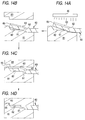
- One of conventional methods of forming a molding having the shape changing area is a stamping technique as shown in Figs. 12A to 12C and 14A to 14D.
- the bottom face 62 of an end portion 61 of an extruded strip 60 having a predetermined size molded by e.g. extrusion as shown in Fig. 12A is cut by a predetermined amount using an edged tool 70 in accordance with a desired molding to provide a shape imparting space 63 there as shown in Fig. 12B and 13A to 13D.
- This is a bottom face cutting (removal) step.
- Symbol 64 is a part which was made unnecessary by cutting.
- the end portion 61 is heated and softened by a heating means 80 such as a heater, and introduced into an end molding portion 82 of a fixed die 81 constituting one part of a stamping die.
- a heating means 80 such as a heater
- a movable die 83 constituting the other part of the stamping die is stamped to push the resin on the designing side of the end portion 61 toward the shape imparting space 63 on the bottom side to provide a die shape.
- This is a thermal stamping step.
- a molding M2 having a desired shape changing area at the end portion as shown in Fig. 12C is obtained.
- the resin on the designing side of the extruded strip is pushed into the shape imparting space on the bottom side to impart a required shape changing area. Therefore, in order to impart the shape easily and precisely, the shape imparting space on the bottom face side must be previously formed in a shape corresponding to the shape changing area after shape imparting.
- a cutting line 63a is made at a predetermined position on the bottom face 62 of the extruded strip 60 in a thickness direction perpendicular to the bottom face, and another cutting line 63b is made in the extruded strip 69 in parallel to the bottom face 62 so as to reach the cutting line 63a in the thickness direction.
- the bottom face area encircled by the cutting lines 63a and 63b in both directions is cut to form the shape imparting space 63.
- the shape imparting space thus formed is rectangular in a longitudinal sectional shape in a longitudinal direction of the extruded strip 60.
- Fig. 13C is a plan view showing the bottom face 62 of the extruded strip 60 shown in Fig. 13B.
- Fig. 13D is a side view viewed from arrow Z in Fig. 13C.
- the shape imparting space 63 on the bottom face does not correspond to the shape of the shape changing area after shape imparting, and non-cut area 65 is left because of using the holding jig. Therefore, in the thermal stamping step, a large amount of resin is extruded into the shape imparting space 63 on the bottom face side from the show face side, and is not completely received in the shape imparting space 63 to provide redundant resin. In this case, the redundant resin moves to the periphery of the shape changing area after shape imparting to provide a large amount of burrs 66 (Fig. 14D). This made complicate the work of removing the burrs after completing the molding.
- the redundant resin since the redundant resin must move the periphery of the shape changing area through the shape imparting space 63, the moving distance of the resin becomes long so that unequal stress is likely to occur within the shape changing area while the resin moves. The stress remains within the shape changing area after shape imparting so that distortion is generated within the shape changing area by releasing the stamping stress. Thus, the appearance of the molding was impaired.
- the present invention has been accomplished in view of the above problems, and intends to provide a method of forming a molding which can reduce the work of removing burrs after stamping, and without being influenced by a difference between the shape of a shape imparting space before shape imparting and that of a shape changing area after shape imparting, prevent unequal stress due to the movement of redundant resin from occurring in stamping, thereby providing a molding with a good appearance.
- a method for forming a molding comprising the steps of: removing a predetermined amount of a bottom face of a predetermined portion of an extruded strip to form a bottom face removal portion having a shape imparting space and a redundant resin accommodating concave area continuous thereto; and heating and softening said bottom face removal portion and stamping it by a stamping die having a predetermined shape to push resin on a show face side corresponding to said shape imparting space toward the shape imparting space on the bottom face side, thereby shaping said bottom face removal portion into a shape of the stamping die and accommodating redundant resin in said redundant resin accommodating concave area.
- said redundant resin accommodating concave area is formed on both sides and one end of said redundant resin accommodating area is continuous to said shape imparting space.
- Fig. 1 is a partial perspective view showing the step of removing the bottom face in a method of forming a molding according to an embodiment of the present invention.
- Fig. 2 is a perspective view showing an extruded strip after completion of the bottom face removing step in the embodiment.
- Fig. 3 is a sectional view along line 3 - 3.
- Fig. 4 is a sectional view showing a heating/softening step in the embodiment.
- Fig. 5 is a sectional view showing an initial stage of a stamping step in the embodiment.
- Fig. 6 is a sectional view showing how redundant resin is accommodated in a redundant resin accommodating concave area.
- Fig. 7 is a sectional view showing the manner when the stamping step has been completed in the embodiment.
- Fig. 8 is a sectional view showing a step of removing burrs in the embodiment.
- a required area of an extruded strip 10 molded successively by e.g. known extrusion technique, a bottom face 11a of an end portion in this embodiment is cut away by a predetermined amount using a suitable means such as a cutting tool or edged tool to form a shape imparting space 15 as shown in Fig. 2 and Fig. 3 showing its section taken along line 3 - 3.
- the above extruded strip 10 is made of known extrudable resin such as vinyl chloride resin (PVC) and acrylonitrile styrene acrylate copolymer (AAS) and is formed of a single or multiple layers.
- the cross sectional shape of the extruded strip 10 is a curved shape with a swelling designing side which conforms to the shape of a common area Mo of a molding M2 to be molded.
- the shape imparting space 15 is made not to obstruct shape imparting when the above end portion 11 is thermally stamped by the subsequent step.
- the shape imparting space 15 is formed by cutting the bottom face 11a using a rotary cutting tool 70 provided with an end mill Ce such as a ball end mill, flat end mill, etc at its tip while both ends 12, 12 are held by a holding jig (not shown) so as to be secured in a receiving die (not shown) so that the extruded strip 10 is not slipped.
- the shape imparting space may be formed in such a manner that a cutting line is made in a thickness direction perpendicular to the bottom face of the end portion by the edged tool, and another cutting line is made in parallel to the bottom face so as to reach the cutting line in the thickness direction and the bottom face area encircled by the cutting lines in both directions is cut (Figs. 13A to 13D).
- the shape of the shape imparting space 15 in this embodiment is composed of a first space 16 which is deep and a second space 17 which is gradually shallow which are continuous to each other. These spaces 16 and 17 correspond to the thin area Mc1 and thickness gradually changing area Mc2 of the shape changing portion Mc of the molding M2 to be molded.
- the shape of the shape imparting space 15 may not strictly correspond to the shape changing portion Mc because of the design of a redundant resin accommodating concave area 20 described later. Namely, the shape of the shape imparting space 15 may be slightly different from that of the shape changing portion after shape imparting.
- a redundant resin accommodating concave area 20 continuous to the shape imparting space 15 is formed.
- This redundant resin accommodating concave portion 20 is formed to accommodate (relieve) the redundant resin which cannot be received in the shape imparting space 15 at the time of thermal stamping described later. In this embodiment, it is formed using the above rotary cutting tool C when the shape imparting space 15 is formed.
- the redundant resin accommodating concave area 20 is formed so that its one end 21 is continuously oriented toward the common portion 13 from the shape imparting space 15 in order to shorten the moving distance of redundant resin at the time of thermal stamping, precisely, that of the redundant resin produced on the side of the common area 13 of the end portion 11 to be molded.
- the redundant resin accommodating concave area 20 is formed at the position where a large amount of redundant resin will be produced at the time of thermal stamping, i.e. a non-cut area not removed by the use of the holding jig B when the shape imparting space 15 is formed (i.e. in the vicinity of the above both ends 12, 12).
- redundant resin accommodating concave areas 20, 20 each having a predetermined length, depth and width are made continuously from both ends 16a, 16a of the first space 16 toward the common area 13, respectively.
- the length, depth and width of the redundant resin accommodating concave area 20 is set suitably taking into consideration the shape of the shape imparting space 15 and shape changing portion Mc after shape imparting. For example, they are set to be long, deep and large when the shape of the shape imparting space 15 is largely different from (not correspond to) that of the shape changing portion Mc after shape imparting, or when the non-cut areas 12, 12 are large.
- the bottom face removed portion (including the show face side as well as the bottom face side) with the shape imparting space 15 of the extruded strip 10 and the redundant resin accommodating concave area 20 is heated and softened by a suitable heating means 30 such as a heater, and introduced into a fixed die 41 of a stamping die 40 with the bottom face removal portion 11 located above.
- a suitable heating means 30 such as a heater
- the heating temperature varies according to the material of the extruded strip 10, heating time, etc.
- the temperature of the heating means although it depends on a heating source, is generally set at about 300 °C in hot air blow.
- the die face 42 of the fixed die 41 has a shape conforming to that of the show face of the shape changing portion Mc of the molding M2 to be machined.
- the above heating may be carried out outside the stamping die 40, or on the fixed die 41 of the stamping die 40.
- the bottom face removal portion 11 of the extruded strip 10 thus heated and softened is shaped into the shape of the die face 42 of the fixed die 42 in such a manner that a movable die 45 is stamped to the fixed die 41 of the stamping die so that the resin P on the show face side corresponding to the shape imparting space 15 of the bottom face removal portion 11 is pushed toward the shape imparting space on the bottom face side.
- the stamping die 40 in this embodiment has the space 46 (Fig. 7) to accommodate the blurrs 50 produced in stamping process, in which the blurrs 50 are on the end side of bottom face removal portion 11 of the extruded strip 10 and are forced out of a parting line of the above fixed mold and moval mold.
- the moving distance of the redundant resin Pe (particularly, the distance when the redundant resin Pe produced on the side of the common portion 13 of the bottom face removal portion 1 moves to the burrs accommodating space 46 formed in the stamping mold at the tip of the bottom face removal portion 1 is shortened, it is possible to prevent movement of the redundant resin from producing unequal stress in the shape changing area Mc. As a result, it is possible to prevent the stress from remaining within the shape changing area after shape imparting so that distortion is generated within the shape changing area after the stamping stress is released, thereby not impairing the appearance of the molding.
- the movable die 45 is elevated to open the stamping mold 40 so that the stamping stress is released, thereby taking out a molded product 10A as shown in Fig. 8. Finally, a small amount of burrs overflowed into the burrs accommodating space of the stamping die 40 at the time of stamping is removed, thereby providing a desired molding.
- the above embodiment was directed to the method of forming a molding for a motor vehicle having a shape changing area at its end area, but the molding method according to the present invention can be applied to the method of forming a molding having a shape changing area at the other portion than the end portion, and can also be applied to the method of forming a molding not used for the motor vehicle.
- the amount of burrs occurring on the periphery of the shape changing portion after shape imparting can be reduced so that the work of removing burrs after stamping.
- moving distance of the redundant resin can be decreased at the time of shape imparting, it is possible to prevent unequal stress due to the movement of redundant resin from occurring in stamping, thereby providing a molding with a good appearance.
Landscapes
- Engineering & Computer Science (AREA)
- Mechanical Engineering (AREA)
- Vehicle Interior And Exterior Ornaments, Soundproofing, And Insulation (AREA)
- Shaping Of Tube Ends By Bending Or Straightening (AREA)
- Casting Or Compression Moulding Of Plastics Or The Like (AREA)
- Blow-Moulding Or Thermoforming Of Plastics Or The Like (AREA)
Applications Claiming Priority (3)
| Application Number | Priority Date | Filing Date | Title |
|---|---|---|---|
| JP27977997A JP3865894B2 (ja) | 1997-09-25 | 1997-09-25 | モールディングの成形方法 |
| JP27977997 | 1997-09-25 | ||
| JP279779/97 | 1997-09-25 |
Publications (3)
| Publication Number | Publication Date |
|---|---|
| EP0904915A2 true EP0904915A2 (de) | 1999-03-31 |
| EP0904915A3 EP0904915A3 (de) | 2000-02-16 |
| EP0904915B1 EP0904915B1 (de) | 2004-11-17 |
Family
ID=17615812
Family Applications (1)
| Application Number | Title | Priority Date | Filing Date |
|---|---|---|---|
| EP19980108067 Expired - Lifetime EP0904915B1 (de) | 1997-09-25 | 1998-05-04 | Verfahren zur Herstellung eines Formteiles |
Country Status (3)
| Country | Link |
|---|---|
| EP (1) | EP0904915B1 (de) |
| JP (1) | JP3865894B2 (de) |
| DE (1) | DE69827574T2 (de) |
Families Citing this family (1)
| Publication number | Priority date | Publication date | Assignee | Title |
|---|---|---|---|---|
| KR102470394B1 (ko) * | 2017-09-29 | 2022-11-23 | 르노코리아자동차 주식회사 | 차량용 도어 몰딩 |
Family Cites Families (5)
| Publication number | Priority date | Publication date | Assignee | Title |
|---|---|---|---|---|
| DE909305C (de) * | 1949-04-30 | 1954-04-15 | Injection Molding Company | Gefaess und Verfahren zu dessen Herstellung |
| US3276941A (en) * | 1963-10-23 | 1966-10-04 | Shell Oil Co | Method for butt-welding thermoplastic members and product |
| US3684582A (en) * | 1970-08-25 | 1972-08-15 | Maurice Roberts | Electric storage batteries |
| JP3589729B2 (ja) * | 1995-02-15 | 2004-11-17 | 株式会社イノアックコーポレーション | モール端末部の加工方法 |
| JP2966314B2 (ja) * | 1995-04-28 | 1999-10-25 | 株式会社イノアックコーポレーション | モールディングの端末加工方法および装置 |
-
1997
- 1997-09-25 JP JP27977997A patent/JP3865894B2/ja not_active Expired - Fee Related
-
1998
- 1998-05-04 EP EP19980108067 patent/EP0904915B1/de not_active Expired - Lifetime
- 1998-05-04 DE DE1998627574 patent/DE69827574T2/de not_active Expired - Lifetime
Also Published As
| Publication number | Publication date |
|---|---|
| DE69827574T2 (de) | 2005-12-01 |
| EP0904915A3 (de) | 2000-02-16 |
| EP0904915B1 (de) | 2004-11-17 |
| DE69827574D1 (de) | 2004-12-23 |
| JPH1199566A (ja) | 1999-04-13 |
| JP3865894B2 (ja) | 2007-01-10 |
Similar Documents
| Publication | Publication Date | Title |
|---|---|---|
| JP3832927B2 (ja) | アクスルケースの製造方法 | |
| US5227108A (en) | Method of forming decorative trim strips | |
| JPH1016043A (ja) | 真空成形装置およびその方法 | |
| EP0904915A2 (de) | Verfahren zur Herstellung eines Formteiles | |
| CN113401070B (zh) | 一种汽车内饰板 | |
| JP3203870B2 (ja) | 樹脂製品の製造方法 | |
| JP4727306B2 (ja) | モールディングの製造方法およびモールディング | |
| EP0904914B1 (de) | Verfahren zur Herstellung eines Formteiles | |
| JP3805872B2 (ja) | モールディングの成形方法 | |
| KR101490753B1 (ko) | 차량용 인스트루먼트패널 제조방법 | |
| JP3751288B2 (ja) | 予備成形用シート折り曲げ型およびこれを用いたインサートシートの予備成形方法 | |
| US5143760A (en) | Extruded molding with desired contoured formation | |
| JP4135937B2 (ja) | 車両用の窓縁モール組立体及びその製造方法 | |
| JPS5914918A (ja) | 合成樹脂チユ−ブの曲げ加工法 | |
| JP2966314B2 (ja) | モールディングの端末加工方法および装置 | |
| JP2586951B2 (ja) | 多層構造体の製造方法 | |
| JPH09225960A (ja) | シートインサート成形用金型及び成形方法 | |
| JP2977755B2 (ja) | 車両用サンバイザの製造方法 | |
| JP2966315B2 (ja) | モールディングの端末加工方法および装置 | |
| JP2001080432A (ja) | 車両装着部材の成形方法 | |
| JP3495187B2 (ja) | モールディングの端末加工方法 | |
| JPH045571B2 (de) | ||
| JPH0620577Y2 (ja) | モール成形用金型装置 | |
| JP3020437B2 (ja) | モールディングの端末加工方法 | |
| JPS643638B2 (de) |
Legal Events
| Date | Code | Title | Description |
|---|---|---|---|
| PUAI | Public reference made under article 153(3) epc to a published international application that has entered the european phase |
Free format text: ORIGINAL CODE: 0009012 |
|
| AK | Designated contracting states |
Kind code of ref document: A2 Designated state(s): DE ES FR GB IT |
|
| AX | Request for extension of the european patent |
Free format text: AL;LT;LV;MK;RO;SI |
|
| PUAL | Search report despatched |
Free format text: ORIGINAL CODE: 0009013 |
|
| AK | Designated contracting states |
Kind code of ref document: A3 Designated state(s): AT BE CH CY DE DK ES FI FR GB GR IE IT LI LU MC NL PT SE |
|
| AX | Request for extension of the european patent |
Free format text: AL;LT;LV;MK;RO;SI |
|
| 17P | Request for examination filed |
Effective date: 20000405 |
|
| AKX | Designation fees paid |
Free format text: DE ES FR GB IT |
|
| 17Q | First examination report despatched |
Effective date: 20021115 |
|
| GRAP | Despatch of communication of intention to grant a patent |
Free format text: ORIGINAL CODE: EPIDOSNIGR1 |
|
| GRAS | Grant fee paid |
Free format text: ORIGINAL CODE: EPIDOSNIGR3 |
|
| GRAA | (expected) grant |
Free format text: ORIGINAL CODE: 0009210 |
|
| AK | Designated contracting states |
Kind code of ref document: B1 Designated state(s): DE ES FR GB IT |
|
| PG25 | Lapsed in a contracting state [announced via postgrant information from national office to epo] |
Ref country code: IT Free format text: LAPSE BECAUSE OF FAILURE TO SUBMIT A TRANSLATION OF THE DESCRIPTION OR TO PAY THE FEE WITHIN THE PRE;WARNING: LAPSES OF ITALIAN PATENTS WITH EFFECTIVE DATE BEFORE 2007 MAY HAVE OCCURRED AT ANY TIME BEFORE 2007. THE CORRECT EFFECTIVE DATE MAY BE DIFFERENT FROM THE ONE RECORDED.SCRIBED TIME-LIMIT Effective date: 20041117 Ref country code: ES Free format text: LAPSE BECAUSE OF FAILURE TO SUBMIT A TRANSLATION OF THE DESCRIPTION OR TO PAY THE FEE WITHIN THE PRESCRIBED TIME-LIMIT Effective date: 20041117 |
|
| REG | Reference to a national code |
Ref country code: GB Ref legal event code: FG4D |
|
| REF | Corresponds to: |
Ref document number: 69827574 Country of ref document: DE Date of ref document: 20041223 Kind code of ref document: P |
|
| ET | Fr: translation filed | ||
| PLBE | No opposition filed within time limit |
Free format text: ORIGINAL CODE: 0009261 |
|
| STAA | Information on the status of an ep patent application or granted ep patent |
Free format text: STATUS: NO OPPOSITION FILED WITHIN TIME LIMIT |
|
| 26N | No opposition filed |
Effective date: 20050818 |
|
| PGFP | Annual fee paid to national office [announced via postgrant information from national office to epo] |
Ref country code: DE Payment date: 20130515 Year of fee payment: 16 Ref country code: GB Payment date: 20130501 Year of fee payment: 16 |
|
| PGFP | Annual fee paid to national office [announced via postgrant information from national office to epo] |
Ref country code: FR Payment date: 20130531 Year of fee payment: 16 |
|
| REG | Reference to a national code |
Ref country code: DE Ref legal event code: R119 Ref document number: 69827574 Country of ref document: DE |
|
| GBPC | Gb: european patent ceased through non-payment of renewal fee |
Effective date: 20140504 |
|
| REG | Reference to a national code |
Ref country code: FR Ref legal event code: ST Effective date: 20150130 |
|
| REG | Reference to a national code |
Ref country code: DE Ref legal event code: R119 Ref document number: 69827574 Country of ref document: DE Effective date: 20141202 |
|
| PG25 | Lapsed in a contracting state [announced via postgrant information from national office to epo] |
Ref country code: DE Free format text: LAPSE BECAUSE OF NON-PAYMENT OF DUE FEES Effective date: 20141202 |
|
| PG25 | Lapsed in a contracting state [announced via postgrant information from national office to epo] |
Ref country code: GB Free format text: LAPSE BECAUSE OF NON-PAYMENT OF DUE FEES Effective date: 20140504 Ref country code: FR Free format text: LAPSE BECAUSE OF NON-PAYMENT OF DUE FEES Effective date: 20140602 |