EP0904914B1 - Verfahren zur Herstellung eines Formteiles - Google Patents
Verfahren zur Herstellung eines Formteiles Download PDFInfo
- Publication number
- EP0904914B1 EP0904914B1 EP19980108066 EP98108066A EP0904914B1 EP 0904914 B1 EP0904914 B1 EP 0904914B1 EP 19980108066 EP19980108066 EP 19980108066 EP 98108066 A EP98108066 A EP 98108066A EP 0904914 B1 EP0904914 B1 EP 0904914B1
- Authority
- EP
- European Patent Office
- Prior art keywords
- bottom face
- extruded strip
- molding
- shape
- area
- Prior art date
- Legal status (The legal status is an assumption and is not a legal conclusion. Google has not performed a legal analysis and makes no representation as to the accuracy of the status listed.)
- Expired - Lifetime
Links
- 238000000465 moulding Methods 0.000 title claims description 59
- 238000000034 method Methods 0.000 title claims description 18
- 238000010438 heat treatment Methods 0.000 claims description 21
- QZGJNFBMYYEFGM-UHFFFAOYSA-N 1-ethyl-n-(phenylmethyl)-4-(tetrahydro-2h-pyran-4-ylamino)-1h-pyrazolo[3,4-b]pyridine-5-carboxamide Chemical compound C=1C=CC=CC=1CNC(=O)C1=CN=C2N(CC)N=CC2=C1NC1CCOCC1 QZGJNFBMYYEFGM-UHFFFAOYSA-N 0.000 description 13
- CUKZXTKQBXLMDO-UHFFFAOYSA-N 2-[(5-hex-1-yn-1-ylfuran-2-yl)carbonyl]-n-methylhydrazinecarbothioamide Chemical compound CCCCC#CC1=CC=C(C(=O)NNC(=S)NC)O1 CUKZXTKQBXLMDO-UHFFFAOYSA-N 0.000 description 8
- 239000011347 resin Substances 0.000 description 8
- 229920005989 resin Polymers 0.000 description 8
- KQNZSZNDAMAKFF-UHFFFAOYSA-N n-(2-aminoethoxymethyl)aniline Chemical compound NCCOCNC1=CC=CC=C1 KQNZSZNDAMAKFF-UHFFFAOYSA-N 0.000 description 7
- 238000010079 rubber tapping Methods 0.000 description 5
- 238000012986 modification Methods 0.000 description 3
- 230000004048 modification Effects 0.000 description 3
- BZHJMEDXRYGGRV-UHFFFAOYSA-N Vinyl chloride Chemical compound ClC=C BZHJMEDXRYGGRV-UHFFFAOYSA-N 0.000 description 2
- 230000008878 coupling Effects 0.000 description 2
- 238000010168 coupling process Methods 0.000 description 2
- 238000005859 coupling reaction Methods 0.000 description 2
- 238000005034 decoration Methods 0.000 description 2
- 229920003023 plastic Polymers 0.000 description 2
- 238000007796 conventional method Methods 0.000 description 1
- 230000000694 effects Effects 0.000 description 1
- 239000000463 material Substances 0.000 description 1
- 238000007493 shaping process Methods 0.000 description 1
- 239000007787 solid Substances 0.000 description 1
Images


Classifications
-
- B—PERFORMING OPERATIONS; TRANSPORTING
- B29—WORKING OF PLASTICS; WORKING OF SUBSTANCES IN A PLASTIC STATE IN GENERAL
- B29C—SHAPING OR JOINING OF PLASTICS; SHAPING OF MATERIAL IN A PLASTIC STATE, NOT OTHERWISE PROVIDED FOR; AFTER-TREATMENT OF THE SHAPED PRODUCTS, e.g. REPAIRING
- B29C43/00—Compression moulding, i.e. applying external pressure to flow the moulding material; Apparatus therefor
- B29C43/32—Component parts, details or accessories; Auxiliary operations
- B29C43/36—Moulds for making articles of definite length, i.e. discrete articles
- B29C43/38—Moulds for making articles of definite length, i.e. discrete articles with means to avoid flashes
-
- B—PERFORMING OPERATIONS; TRANSPORTING
- B23—MACHINE TOOLS; METAL-WORKING NOT OTHERWISE PROVIDED FOR
- B23C—MILLING
- B23C3/00—Milling particular work; Special milling operations; Machines therefor
-
- B—PERFORMING OPERATIONS; TRANSPORTING
- B29—WORKING OF PLASTICS; WORKING OF SUBSTANCES IN A PLASTIC STATE IN GENERAL
- B29C—SHAPING OR JOINING OF PLASTICS; SHAPING OF MATERIAL IN A PLASTIC STATE, NOT OTHERWISE PROVIDED FOR; AFTER-TREATMENT OF THE SHAPED PRODUCTS, e.g. REPAIRING
- B29C67/00—Shaping techniques not covered by groups B29C39/00 - B29C65/00, B29C70/00 or B29C73/00
- B29C67/0044—Shaping techniques not covered by groups B29C39/00 - B29C65/00, B29C70/00 or B29C73/00 for shaping edges or extremities
-
- B—PERFORMING OPERATIONS; TRANSPORTING
- B29—WORKING OF PLASTICS; WORKING OF SUBSTANCES IN A PLASTIC STATE IN GENERAL
- B29C—SHAPING OR JOINING OF PLASTICS; SHAPING OF MATERIAL IN A PLASTIC STATE, NOT OTHERWISE PROVIDED FOR; AFTER-TREATMENT OF THE SHAPED PRODUCTS, e.g. REPAIRING
- B29C2793/00—Shaping techniques involving a cutting or machining operation
- B29C2793/0081—Shaping techniques involving a cutting or machining operation before shaping
-
- B—PERFORMING OPERATIONS; TRANSPORTING
- B29—WORKING OF PLASTICS; WORKING OF SUBSTANCES IN A PLASTIC STATE IN GENERAL
- B29L—INDEXING SCHEME ASSOCIATED WITH SUBCLASS B29C, RELATING TO PARTICULAR ARTICLES
- B29L2031/00—Other particular articles
- B29L2031/30—Vehicles, e.g. ships or aircraft, or body parts thereof
- B29L2031/3005—Body finishings
- B29L2031/302—Trim strips
Definitions
- the present invention relates to a method for forming a molding having a shape changing area at a predetermined position.
- strip-belt moldings M1 and M2 of plastic are attached to the area of doors Df and Dr on the side of a motor vehicle C in a longitudinal direction of a body.
- each of the above moldings M1 and M2 has a predetermined shape in order to prevent interference between the ends in door opening/closing or from the standpoint of design.
- the front end M2f of the rear molding M2 is formed in a "rear-cut shape" in which it extends from a shape changing area Mc composed of an end side thin area Mc1 and a thickness gradually changing area Mc2 to a common area Mo. This intends to avoid the interference between the molding M2 and a front door Df or the rear portion of the front molding M1 when a rear door Dr is opened.
- the shape changing area Mc may be provided in the other area than the end portion.
- the molding used in the other application field than the motor vehicle also may also require a shape changing area in which a designing side is recessed to a rear side to form a required thin shape.
- a thermal stamping is a thermal stamping.
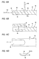
- a cutting line 94 is made in the bottom face 62 extending over a predetermined distance from the end face 92 of an end portion 91 in a thickness direction perpendicular to the bottom face 93, and using another edged tool 100, a cutting line 95 is made in parallel to the bottom face 93 of the end portion 91 from the end face thereof so as to reach an internal end of the cutting line 63a in the thickness direction.
- the bottom face area 96 sectioned by the parting lines 94 and 95 in both directions as shown in Figs. 10A and 10B is removed. This is a bottom face removal step.
- Fig. 10C is a plan view showing the bottom face 93 of the extruded strip 90 shown in Figs. 10B.
- Fig. 10D is a side view viewed from arrow Z in Fig. 10C.
- Fig. 11 is a perspective view of the extruded strip 90 with the bottom face thus removed.
- Reference numeral 97 denotes a removed unnecessary portion, and reference numeral 98 denotes a recessed bottom face removal area formed by removal.
- a heating/softening step is performed which heats/softens the bottom face removal portion 98 formed in the extruded strip 90 using a heating device 101 such as a heater
- a stamping step is performed which stamps the extruded strip 90 by a stamping die 105 with a die face 106 having a desired molding end portion shape to push a show face side of the end portion 91 to the bottom face removal portion side so that the end portion is shaped into the die shape.
- a molding having a desired end portion shape is shaped.
- the space accommodating burrs is located outside position set with extruded strip within the stamping die to accommodate the burrs in pressing the extruded strip.
- the above conventional molding technique removes the bottom face area which is sectioned by a cutting face perpendicular to the bottom face of the extruded strip and another cutting face in parallel to the bottom face. Therefore, as shown in Fig. 11, the bottom face removal portion 98 after an unnecessary portion 97 has been removed is always a hollow having a shape substantially in parallel to the longitudinal direction of the extruded strip.
- the shape of the shape changing area after molding is uncertain since it has different shapes according to a required function and decoration.
- the end portion of a molding M2 for a motor vehicle shown in Fig. 8 includes a gradually changing area Mc2 whose thickness becomes gradually thin and show face is inclined, and a constant thin area whose thickness remains substantially thin. The tip of the end portion is a chamfered area Md.
- the conventional molding technique removes the bottom face in a predetermined shape and thickness (depth) by both cutting lines in perpendicular and parallel directions to the bottom face of the extruded strip. Therefore, the shape of the bottom face removal portion did not conform to that of the objective shape changing area of the molding.
- the stamping step after heating/softening when the resin on the show face side is pushed toward the bottom face removal portion for its shaping, the shape is changed forcibly. This gives rise to inconveniences such as difficulty of being shaped into a prescribed shape, generation of unequal stress to give a distortion to the shape changing area of the resultant molding, abundance of resin on the designing side pushed to the bottom face removal portion to produce of high amounts of burrs, etc.
- the device used in the above bottom face removal apparatus includes a vertical edged tool which moves perpendicularly to the bottom face of the extruded strip held on a stand and horizontal edged tool which moves in parallel to the bottom face of the extruded strip. Therefore, the above vertical and horizontal edged tools could not freely remove the bottom face of the extruded strip. Accordingly, it was difficult to cause the bottom face removal portion to conform to the shape changing portion.
- JP 08300473 A refers to a method of forming a molding with a shape changing area at a predetermined portion of a extruded strip.
- the method comprises a bottom face removal step, a heating/softening step and a stamping step.
- predetermined portion of the extruded strip is removed.
- the bottom face area which is removed from the extruded strip has a cutting face perpendicular to the bottom face of the extruded strip.
- the shape of the bottom face removal portion does not correspond to that of the molding die and the finished extruded strip.
- the present invention has been accomplished under the above circumstance, and intends to provide a method and apparatus for forming a molding which is excellent in appearance of the shape changing portion, difficult to give a distortion to a shape changing portion, and further capable of reducing the generated amount of burrs.
- a rotary cutting blade is moved three-dimensionally while it is put on the bottom face of the predetermined portion of the extruded strip to remove bottom face to have a shape and depth corresponding to the shape of the shape changing area.
- a molding device 10 according to an embodiment of the present invention as shown in Figs. 1 and 2 is used for a bottom face removal step when a molding having a shape changing area at its end portion is thermally stamped from an extruded strip.
- the molding device 10 is provided with receiving sections 20A, 20B; pressing/securing means 30A, 30B; and rotating/cutting means 40A, 40B on a stand 11.
- the stand 11 serves to hold the respective components of the molding device such as the receiving sections 20A, 20B, and has a box shape with a prescribed height in this embodiment.
- the one attaching plate 13B is attached on a rail R arranged on the upper surface of the stand 11 so that it can move from and to the other attaching plate 13A. The movement of the one attaching plate 13B permits its distance from the other attaching plate 13A to vary.
- the attaching plate 13B can move forward and backward in such a manner that a cylinder device (not shown) is attached to the stand 11 so that its operating member is in parallel to the direction between both attaching plates 13A, 13B and the tip of the operating member is secured to the attaching plate 13B.
- the receiving sections 20A and 20B serve to support the end portion of an extruded strip continuously extruded to have a prescribed length, i.e. a portion constituting a shape changing area so that its bottom face is oriented upward.
- the receiving section 20A (20B) has, on the upper surface of a substantial rectangular solid, a concave groove 21A (21B) is formed which has a sectional shape conforming to that on the designing side of the extruded strip.
- These receiving sections 20A, 20B are attached to the attaching plates 13A, 13B, respectively so that the concave grooves 21A, 21B are linear.
- two grooves, i.e. the above concave grooves 21A and 21B are formed in parallel on the corresponding receiving sections 20A and 20B so that those for the left and right doors of a motor vehicle can be simultaneously machined.
- the pressing/securing means 30A (30B) serves to press the bottom face of the end portion of the extruded strip arranged on the concave groove 21A (21B) of the receiving section 20A (20B) to secure the end portion of the extruded strip.
- the pressing/securing means 30A (30B) includes a pressing plate 31A (31B) located above the receiving section 20A (20B) and a vertical movement device 35A (35B) for supporting the pressing plate 31A (31B) so as to be vertically movable over the receiving section 20A (20B).
- the pressing/securing plate 31A (31B) is shaped in a planar shape having a larger than the receiving section 20A (20B).
- the pressing/securing plate 31A (31B) has a rectangular opening 32A (32B) corresponding to the concave groove 21A (21B) of the receiving section 20A (20B).
- the opening 32A (32B) has a width D which is smaller than the width d of the convex groove 21A (21B) of the receiving section 20A (20B) (size in a direction orthogonal to the longitudinal direction) so that the edges in the width direction of the bottom face of the extruded strip arranged in the concave groove 21A (21B) can be pressed.
- the length L of the opening 32A (32B) is determined so that the end portion 65 of the extruded strip 60 is located within the opening 32A (32B) so that a cutting blade 48A (48B) which is to be inserted into the opening 32A (32B) from above can cut an end tip 66 of the extruded strip 60 (Figs. 3A and 3B).
- the vertical movement device 35A (35B) includes a cylinder device 36A (36B) with an operating member 37A (37B) oriented downward on the bottom face of the attaching plate 13A, a rectangular plate 38A (38B) attached to the lower end of the operating member 37A (37B) and coupling rods 39A (39B) which are attached upward at four corners of the plate 38A (38B) to penetrate through the upper surface of the stand 11 and pass outside the four corners of the receiving section 20A (20B) to extend upwards.
- the pressing plate 31A (31B) is secured to the upper ends of the coupling rods 39A (39B), and is adapted to move from and to the receiving section 20A (20B) by the rise/fall of the operating member 37A (37B) of the cylinder device 36A (36B).
- a rotary cutting means 40A (40B) serves to machine the bottom face of the end portion of the extruded strip arranged in the concave groove 21A (21B) of the receiving section 20A (20B) so that the bottom face has a planar shape and depth conforming to the shape changing portion of a molding.
- the rotary cutting means 40A (40B) includes a pillar-shaped supporting member 41A secured to the attaching plate 13A (13B), a movable member 42A (42B) attached to the supporting member 41A and a rotary cutting blade driving member 47A (47B).
- One of the two rotary cutting means 40A (40B) serves to cut the bottom face of one end portion of one of two extruded strips arranged in parallel on the receiving section 20A (20B), whereas the other of the rotary cutting means 40A (40B) serves to cut the one end portion of another extruded strip on the opposite side to the one end portion of the above one extruded strip.
- the movable member 42A which is called “three-axis robot" serves to move the rotary cutting blade driving member 47A (47B) for the bottom face of the end portion of the extruded strip arranged on the receiving section 20A (20B) by a desired degree three-dimensionally in orthogonal three axial directions (i.e. X-, Y- and Z-directions in Fig. 2) in accordance with the shape changing portion of the molding.
- the movable member 42A (42B) includes a first movable component 43A (43B), which is arm-shaped, attached to the upper end of the supporting member 41A (41B) so as to be in parallel to the upper face of the supporting member 41A (41B) and is rotatable by a desired angle on the supporting member 41A (41B), and a second movable member 46A (46B), which is pillar-shaped and attached to the first movable member 43A (43B) so as to be movable by a desired distance between the tip 44A (44B) and stem 45A (45B) of the first movable member 43A (43B) in a horizontal direction and movable by a desired distance in a vertical direction.
- a first movable component 43A (43B) which is arm-shaped, attached to the upper end of the supporting member 41A (41B) so as to be in parallel to the upper face of the supporting member 41A (41B) and is rotatable by a desired angle on the supporting
- the rotation, horizontal movement and vertical movement of the movable member 42A (42B) are carried out by a driving motor (not shown), and its movable amount is controlled by a known electrical control means in accordance with a program previously determined correspondingly to the shape changing area of the molding.
- the rotary cutting blade driving member 47A (47B) includes a driving motor (not shown) for rotating a rotary shaft oriented downward (not shown) and a rotary cutting blade 48A (48B) attached to the rotary shaft, and serves to machine (cut/remove) the bottom face of the end portion of the extruded strip arranged on the receiving section 20A (20B) by its three-dimensional movement by the movable member 42A (42B) so that the bottom face has a planar shape and depth conforming to the shape changing portion of the molding.
- the rotary cutting blade 48A (48B) which is equipped with blades on the side and bottom of its shaft, may be a ball-end mill, or flat end mill which is simply called "end mill". In order to perform the cutting at high precision, the ball-end mill is preferably used as the rotary cutting blade 48A (48B).
- a positioning means 50 for positioning the tip of the end portion of the extruded strip is provided on the attaching plate 13A (13B).
- the positioning means 50A (50B) includes a tapping member 51A (51B) which moves from and to the outer end 22A (22B) of the concave groove 21A (21B) of the receiving section 20A (20B) and a cylinder device 52A (52B) for moving the tapping member 51A (51B).
- the extruded strip is positioned in such a manner that it is arranged on the receiving section 20A (20B) while the tip of its end portion is caused to put on the tapping member 51A moved forward to a prescribed position.
- the tapping member 51A (51B) is left from the outer end of the receiving section 20A (20B) so that the cutting of the tip of the end portion of the extruded strip is not obstructed by the tapping member 51A (51B).
- the one attaching plate 13B is moved forward and backward on the rail R to adjust its distance from the other attaching plate 13A so that the interval between the receiving sections 20A and 20B and between others can be optimally set.
- the molding apparatus can be operated by an operating section which is electrically connected to the respective members described above and arranged on the stand 11.
- the method for forming a molding according to the present invention uses a thermal stamping used conventionally, and comprises a bottom face removal step, a heating/softening step and a stamping step.
- an extruded strip 60 of plastic such as vinyl chloride resin is prepared which is continuously extruded in accordance with a desired molding shape and cut in a prescribed length.
- the extruded strip 60 is similar to the extruded strip 90 shown in Fig. 9 in connection with the description of the prior art.
- the end portion 65 of the extruded strip 60 is arranged in the concave groove 21A (21B) of the receiving section 20A (20B) of the molding apparatus 10.
- the one attaching plate 13B moves forward or backward by the operation of the cylinder device to shift the receiving section 20A (20B), pressing/securing means 30A (30B), rotary cutting means 40A (40B) and positioning means 50A (50B) are moved to right positions for the length of the extruded strip so that the end portion 65 of the extruded strip 60 can be rightly arranged in the concave groove 21A (21B) of the receiving section 20A (20B).
- the pressing plate 31A (31B) of the pressing/securing means 30A (30B) is lowered to press the bottom face 67 of the end portion 65 of the extruded strip 60 on the receiving section 20A (20B) downward so that the extruded strip is secured to the receiving section 20A (20B).
- the opening 32A (32B) of the pressing plate 31A (31B) the bottom face 67 of the end portion 65 of the extruded strip 60 is exposed.
- the securing member 51A (51B) of the positioning means 50A (50B) retracts from the end face 66 of the extruded strip 60.
- the rotary cutting blade 48A (48B) of the rotary cutting means 40A (40B) is lowered into the opening 32A (32B) of the pressing plate 31A (31B) by the operation of the second movable component 46A (46B) so as to cut/remove the bottom face 67 of the end portion 65 of the extruded strip in the opening 32A (32B) while it moves three-dimensionally in accordance with a program prepared so as to correspond to a desired shape changing area, i.e. end shape of the molding.
- the cutting/removal of the bottom face of the extruded strip corresponding to the shape changing area of the molding is to not only cut/remove the area corresponding to the shape changing area having a large or small thickness by a shallow or a deep degree, but also cut/remove the shape changing area in accordance with its planar shape.
- the rotary cutting blade 48A (48B) and the pressing plate 31A (31B) are successively elevated so that the extruded strip after the bottom face removal is detached from the receiving section 20A (20B) of the molding apparatus 10.
- the extruded strip with the bottom face removal area 68 formed as shown in Fig. 4 is formed.
- the bottom face removal area of the extruded strip 60 acquired by the bottom face removal step is heated by a heating means such as a heater as shown in Fig. 5 so that it is softened.
- the heating temperature at this time is a temperature enough to deform the vicinity of the bottom face removal area 68 of the extruded strip 60 by stamping. It differs according to a material, heating time, etc. of the extruded strip.
- the temperature of the heating means 70 although it depends on a heating source, is set at about 300 °C in the case of hot air blow.
- the heating/softening step can be carried out on a heating jig (not shown).
- the bottom face removal area 68 of the extruded strip 60 after the above heating/softening step is stamped by the stamping die 80 as shown in Fig. 6 and shaped in a desired shape changing area (end area).
- the stamping die 80 conforms to the shape of the shape changing area (end area) of the molding. It includes a receiving die 81 having a die face 82 on which the show face 68 of the bottom face removal area of the extruded strip 60 is arranged, and also a pressing die 85 for pressing the bottom face of the extruded strip 60.
- the pressing die 85 can be risen or fallen for the receiving die 81 by a known stamping apparatus (not shown).
- the bottom face removal area 68 of the extruded strip 60 in a softened state whose bottom face has been removed in a shape and depth corresponding to the objective shape changing area of the molding
- the resin on the side of the show face 68a moves smoothly into the space (the area designated by numeral 69 in Fig. 5) cut in the bottom face removal area 68 so that it is shaped in a shape of the die face 82, thus producing the objective shape changing area Mc with a good appearance.
- the forcible movement of resin is reduced so that unequal stress such as sharing stress is not stored in the shape changing area Mc, thereby making it to generate distortion in the resultant shape changing area Mc difficult.
- the resin overflowing from the space 69 cut in the bottom face removal area 68 is reduced so that minor amounts of burrs is generated, thus making the subsequent work of removing the burrs easy.
- the molding method and apparatus according to the present invention is not limited to the case where the shape changing are is formed at the end portion. This can be easily understood from the description hitherto made and can be put into practice in some modifications as necessity requires.
- the method of forming a molding according to the present invention when a molding having a shape changing area at a desired position is formed from an extruded strip by thermal stamping, performs the bottom face removal step by cutting the bottom face of the extruded strip in a planar shape and depth corresponding to the shape changing area. For this reason, in the stamping step after the heating/softening step, the bottom face removal portion can be shaped easily and precisely in a desired shape changing area. In addition, unequal stress due to forcible movement and deformation of the resin is difficult to occur so that deformation of the shape changing area due to the stress can be suppressed, thereby permitting the molding with a good appearance to be provided. Further, the amount of burrs due to redundant resin which will be produced in the stamping step after the heating/softening can be reduced. This simplifies the work of removing the burrs.
- the molding apparatus described above unlike moving an edged tool perpendicularly and in parallel to the bottom face of the extruded strip according to the prior art, moves a rotary cutting blade called "end mill" three-dimensionally for the bottom face of the extruded strip.
- the bottom face of the extruded strip can be cut/removed so as to correspond to the planar shape and depth of the objective shape changing area.
- the molding having a shape changing area with a good appearance can be easily obtained, and the work of removing the burrs in the molding can be simplified.
Landscapes
- Engineering & Computer Science (AREA)
- Mechanical Engineering (AREA)
- Vehicle Interior And Exterior Ornaments, Soundproofing, And Insulation (AREA)
- Casting Or Compression Moulding Of Plastics Or The Like (AREA)
- Shaping Of Tube Ends By Bending Or Straightening (AREA)
Claims (2)
- Verfahren zum Formen eines Formteils mit einem Formveränderungsbereich in einem vorgegebenen Teil eines extrudierten Streifens (60), in dem sich die Form einer Gestaltungsseite (62) des vorgegebenen Teils verändert, umfassend die folgenden Schritte:dadurch gekennzeichnet, dass in dem Bodenseitenentfernungsschritt der vorgegebene Teil des extrudierten Streifens (60) so entfernt wird, dass er eine ebene Form und eine Tiefe entsprechend der einer Werkzeugoberfläche eines Presswerkzeugs (80) und des Formveränderungsbereichs aufweist.einen Bodenseitenentfernungsschritt zur Entfernung der Bodenseite (67) eines vorgegebenen Teils des extrudierten Streifens (60), um einen Bodenseitenentfernungsteil (68) auszubilden;einen Erhitzungs-/Erweichungsschritt zum Erhitzen/Erweichen des Bodenseitenentfernungsteils des extrudierten Streifens (60); undeinen Pressschritt zum Pressen des Bodenseitenentfernungsteils (68) des extrudierten Streifens (60) durch das Presswerkzeug, dessen Oberfläche (82) dem Formveränderungsbereich entspricht, um diesen in der Form des Werkzeugs zu formen,
- Verfahren zum Formen eines Formteils gemäß Anspruch 1, wobei in dem Bodenseitenentfernungsschritt eine rotierende, spanabhebende Klinge (48A, B) dreidimensional bewegt wird, während sie auf der Bodenseite (67) des vorgegebenen Teils des extrudierten Streifens (60) aufgesetzt ist, wodurch die Bodenseite (67) so entfernt wird, dass sie eine ebene Form und eine Tiefe entsprechend der Form des Formeränderungsbereichs ausbildet.
Applications Claiming Priority (3)
| Application Number | Priority Date | Filing Date | Title |
|---|---|---|---|
| JP27978097A JP3865895B2 (ja) | 1997-09-25 | 1997-09-25 | モールディングの成形方法 |
| JP27978097 | 1997-09-25 | ||
| JP279780/97 | 1997-09-25 |
Publications (3)
| Publication Number | Publication Date |
|---|---|
| EP0904914A2 EP0904914A2 (de) | 1999-03-31 |
| EP0904914A3 EP0904914A3 (de) | 2000-02-16 |
| EP0904914B1 true EP0904914B1 (de) | 2005-09-14 |
Family
ID=17615826
Family Applications (1)
| Application Number | Title | Priority Date | Filing Date |
|---|---|---|---|
| EP19980108066 Expired - Lifetime EP0904914B1 (de) | 1997-09-25 | 1998-05-04 | Verfahren zur Herstellung eines Formteiles |
Country Status (3)
| Country | Link |
|---|---|
| EP (1) | EP0904914B1 (de) |
| JP (1) | JP3865895B2 (de) |
| DE (1) | DE69831542T2 (de) |
Families Citing this family (3)
| Publication number | Priority date | Publication date | Assignee | Title |
|---|---|---|---|---|
| US6224145B1 (en) * | 1998-10-30 | 2001-05-01 | Inoac Corporation | Roof molding for an automobile and method of trimming the same |
| US9174519B2 (en) | 2011-10-18 | 2015-11-03 | Henniges Automotive Sealing Systems North America Inc. | Weatherstrip assembly having a variable length shim |
| KR102470394B1 (ko) * | 2017-09-29 | 2022-11-23 | 르노코리아자동차 주식회사 | 차량용 도어 몰딩 |
Family Cites Families (5)
| Publication number | Priority date | Publication date | Assignee | Title |
|---|---|---|---|---|
| FR2503023A1 (fr) * | 1981-04-01 | 1982-10-08 | Essilor Int | Monture de lunette en materiau stratifie et son procede de fabrication |
| DE3802396A1 (de) * | 1988-01-25 | 1989-08-03 | Tokiwa Chem Ind Ltd | Ornamentalband aus synthetischem harz und verfahren zu seiner herstellung |
| JPH06190619A (ja) * | 1992-12-22 | 1994-07-12 | Iwai Tangata Seisakusho:Yugen | 三次元倣いフライス盤と彫成方法 |
| JP3589729B2 (ja) * | 1995-02-15 | 2004-11-17 | 株式会社イノアックコーポレーション | モール端末部の加工方法 |
| JP2966314B2 (ja) * | 1995-04-28 | 1999-10-25 | 株式会社イノアックコーポレーション | モールディングの端末加工方法および装置 |
-
1997
- 1997-09-25 JP JP27978097A patent/JP3865895B2/ja not_active Expired - Fee Related
-
1998
- 1998-05-04 DE DE1998631542 patent/DE69831542T2/de not_active Expired - Lifetime
- 1998-05-04 EP EP19980108066 patent/EP0904914B1/de not_active Expired - Lifetime
Also Published As
| Publication number | Publication date |
|---|---|
| DE69831542T2 (de) | 2006-06-22 |
| JPH1199567A (ja) | 1999-04-13 |
| EP0904914A2 (de) | 1999-03-31 |
| JP3865895B2 (ja) | 2007-01-10 |
| DE69831542D1 (de) | 2005-10-20 |
| EP0904914A3 (de) | 2000-02-16 |
Similar Documents
| Publication | Publication Date | Title |
|---|---|---|
| DE102008011808B4 (de) | Verfahren und Vorrichtung zum Entfernen der Glasformnähte mit Polieren der Nahtstellen sowie dadurch bearbeitetes Glasprodukt | |
| KR100773848B1 (ko) | 박판 성형 방법 및 장치 | |
| DE112012003796B4 (de) | Bearbeitungsdatenerzeugungsverfahren für kombinierte Ultrapräzisionsbearbeitungsvorrichtung und kombinierte Ultrapräzisionsbearbeitungsvorrichtung | |
| US20020100750A1 (en) | Rapid prototyping method using 3-D laser inner cutting | |
| JP2001058295A (ja) | 成形用プレス装置 | |
| EP0904914B1 (de) | Verfahren zur Herstellung eines Formteiles | |
| CN104249242A (zh) | 用于批量生产热压印冷切边的压模及其制造方法 | |
| US5398572A (en) | Press die assembly and method for producing the same | |
| WO2001064415A1 (de) | Vorrichtung zum herstellen eines zumindest einseitig mit einem textil versehenen spritzgussteils | |
| KR20040086090A (ko) | 순차 성형가공방법 및 장치 | |
| US6007280A (en) | Production method of pattern for casting | |
| US11034077B2 (en) | Thermoforming mold trimming system and process | |
| JP3564778B2 (ja) | 金型の切削加工方法 | |
| CN100431784C (zh) | 切削装置 | |
| JP2000153336A (ja) | ステアリングラックの製造方法 | |
| CN112828153B (zh) | 可旋转切削去毛刺的切边整形模具 | |
| US5230910A (en) | Apparatus for the cold deep drawing of films | |
| EP0904915B1 (de) | Verfahren zur Herstellung eines Formteiles | |
| CN214489588U (zh) | 一种模内加工模具 | |
| JP2600475B2 (ja) | パネルの切断成形機 | |
| JP2006021253A (ja) | 板金製品の製造方法 | |
| JP3405077B2 (ja) | プレス装置とプレス成形部材及びその成形加工方法 | |
| JP2022021578A (ja) | 基材および基材の製造方法 | |
| KR20020069598A (ko) | 버어 제거장치 | |
| JP2007098822A (ja) | 三次元造形方法 |
Legal Events
| Date | Code | Title | Description |
|---|---|---|---|
| PUAI | Public reference made under article 153(3) epc to a published international application that has entered the european phase |
Free format text: ORIGINAL CODE: 0009012 |
|
| AK | Designated contracting states |
Kind code of ref document: A2 Designated state(s): DE ES FR GB IT |
|
| AX | Request for extension of the european patent |
Free format text: AL;LT;LV;MK;RO;SI |
|
| PUAL | Search report despatched |
Free format text: ORIGINAL CODE: 0009013 |
|
| AK | Designated contracting states |
Kind code of ref document: A3 Designated state(s): AT BE CH CY DE DK ES FI FR GB GR IE IT LI LU MC NL PT SE |
|
| AX | Request for extension of the european patent |
Free format text: AL;LT;LV;MK;RO;SI |
|
| 17P | Request for examination filed |
Effective date: 20000405 |
|
| AKX | Designation fees paid |
Free format text: DE ES FR GB IT |
|
| 17Q | First examination report despatched |
Effective date: 20021115 |
|
| GRAP | Despatch of communication of intention to grant a patent |
Free format text: ORIGINAL CODE: EPIDOSNIGR1 |
|
| RTI1 | Title (correction) |
Free format text: METHOD FOR FORMING A MOLDING |
|
| RIN1 | Information on inventor provided before grant (corrected) |
Inventor name: MURAGUCHI, KOICHI,C/O INOAC CORPORATION Inventor name: INOUE, KOJI,C/O INOAC CORPORATION Inventor name: SUGIURA, MASATOSHI,C/O INOAC CORPORATION |
|
| GRAS | Grant fee paid |
Free format text: ORIGINAL CODE: EPIDOSNIGR3 |
|
| GRAA | (expected) grant |
Free format text: ORIGINAL CODE: 0009210 |
|
| AK | Designated contracting states |
Kind code of ref document: B1 Designated state(s): DE ES FR GB IT |
|
| PG25 | Lapsed in a contracting state [announced via postgrant information from national office to epo] |
Ref country code: IT Free format text: LAPSE BECAUSE OF FAILURE TO SUBMIT A TRANSLATION OF THE DESCRIPTION OR TO PAY THE FEE WITHIN THE PRESCRIBED TIME-LIMIT;WARNING: LAPSES OF ITALIAN PATENTS WITH EFFECTIVE DATE BEFORE 2007 MAY HAVE OCCURRED AT ANY TIME BEFORE 2007. THE CORRECT EFFECTIVE DATE MAY BE DIFFERENT FROM THE ONE RECORDED. Effective date: 20050914 |
|
| REG | Reference to a national code |
Ref country code: GB Ref legal event code: FG4D |
|
| REF | Corresponds to: |
Ref document number: 69831542 Country of ref document: DE Date of ref document: 20051020 Kind code of ref document: P |
|
| PG25 | Lapsed in a contracting state [announced via postgrant information from national office to epo] |
Ref country code: ES Free format text: LAPSE BECAUSE OF FAILURE TO SUBMIT A TRANSLATION OF THE DESCRIPTION OR TO PAY THE FEE WITHIN THE PRESCRIBED TIME-LIMIT Effective date: 20051225 |
|
| PLBE | No opposition filed within time limit |
Free format text: ORIGINAL CODE: 0009261 |
|
| STAA | Information on the status of an ep patent application or granted ep patent |
Free format text: STATUS: NO OPPOSITION FILED WITHIN TIME LIMIT |
|
| 26N | No opposition filed |
Effective date: 20060615 |
|
| PG25 | Lapsed in a contracting state [announced via postgrant information from national office to epo] |
Ref country code: FR Free format text: LAPSE BECAUSE OF FAILURE TO SUBMIT A TRANSLATION OF THE DESCRIPTION OR TO PAY THE FEE WITHIN THE PRESCRIBED TIME-LIMIT Effective date: 20061020 |
|
| EN | Fr: translation not filed | ||
| EN | Fr: translation not filed | ||
| PG25 | Lapsed in a contracting state [announced via postgrant information from national office to epo] |
Ref country code: FR Free format text: LAPSE BECAUSE OF FAILURE TO SUBMIT A TRANSLATION OF THE DESCRIPTION OR TO PAY THE FEE WITHIN THE PRESCRIBED TIME-LIMIT Effective date: 20050914 |
|
| PGFP | Annual fee paid to national office [announced via postgrant information from national office to epo] |
Ref country code: GB Payment date: 20130501 Year of fee payment: 16 Ref country code: DE Payment date: 20130515 Year of fee payment: 16 |
|
| REG | Reference to a national code |
Ref country code: DE Ref legal event code: R119 Ref document number: 69831542 Country of ref document: DE |
|
| GBPC | Gb: european patent ceased through non-payment of renewal fee |
Effective date: 20140504 |
|
| REG | Reference to a national code |
Ref country code: DE Ref legal event code: R119 Ref document number: 69831542 Country of ref document: DE Effective date: 20141202 |
|
| PG25 | Lapsed in a contracting state [announced via postgrant information from national office to epo] |
Ref country code: DE Free format text: LAPSE BECAUSE OF NON-PAYMENT OF DUE FEES Effective date: 20141202 |
|
| PG25 | Lapsed in a contracting state [announced via postgrant information from national office to epo] |
Ref country code: GB Free format text: LAPSE BECAUSE OF NON-PAYMENT OF DUE FEES Effective date: 20140504 |