EP0904850A2 - Dispositif d'application - Google Patents
Dispositif d'application Download PDFInfo
- Publication number
- EP0904850A2 EP0904850A2 EP98113961A EP98113961A EP0904850A2 EP 0904850 A2 EP0904850 A2 EP 0904850A2 EP 98113961 A EP98113961 A EP 98113961A EP 98113961 A EP98113961 A EP 98113961A EP 0904850 A2 EP0904850 A2 EP 0904850A2
- Authority
- EP
- European Patent Office
- Prior art keywords
- ribs
- support tube
- insert
- tube
- paint
- Prior art date
- Legal status (The legal status is an assumption and is not a legal conclusion. Google has not performed a legal analysis and makes no representation as to the accuracy of the status listed.)
- Withdrawn
Links
- 239000003973 paint Substances 0.000 claims abstract description 20
- 230000004323 axial length Effects 0.000 claims abstract description 4
- 239000007788 liquid Substances 0.000 claims description 6
- 238000004140 cleaning Methods 0.000 description 2
- 239000002131 composite material Substances 0.000 description 1
- 238000010276 construction Methods 0.000 description 1
- 230000003670 easy-to-clean Effects 0.000 description 1
Images


Classifications
-
- B—PERFORMING OPERATIONS; TRANSPORTING
- B05—SPRAYING OR ATOMISING IN GENERAL; APPLYING FLUENT MATERIALS TO SURFACES, IN GENERAL
- B05C—APPARATUS FOR APPLYING FLUENT MATERIALS TO SURFACES, IN GENERAL
- B05C17/00—Hand tools or apparatus using hand held tools, for applying liquids or other fluent materials to, for spreading applied liquids or other fluent materials on, or for partially removing applied liquids or other fluent materials from, surfaces
- B05C17/02—Rollers ; Hand tools comprising coating rollers or coating endless belts
- B05C17/03—Rollers ; Hand tools comprising coating rollers or coating endless belts with feed system for supplying material from an external source or with a reservoir or container for liquid or other fluent material located in or on the hand tool outside the coating roller
- B05C17/0308—Rollers ; Hand tools comprising coating rollers or coating endless belts with feed system for supplying material from an external source or with a reservoir or container for liquid or other fluent material located in or on the hand tool outside the coating roller the liquid being supplied to the inside of the coating roller
Definitions
- the invention relates to a device for applying liquids, especially of paint on a wall, consisting of one on a conveyor line connectable support tube provided with radially directed outlet openings, a color distributor rotatably arranged on this and one on this held application roller provided with a perforated support tube.
- the color distributor is here a variety of modular Sections formed with a regular polygonal cross section, the one enclose large interior and arranged angularly next to each other are. From the interior communicating with the support tube via bores the sections clamped together by tie rods flows through the Paint to be fed through the open slots in the outer grooves of the adjacent sections and from these to the roller.
- the object of the invention is therefore a device for applying Form liquids of the aforementioned type in such a way that always satisfactory color distribution over a long period of operation is given. Furthermore, it should be achieved that a complete cleaning of the Color distributor can be made in a short time without difficulty and that only a small amount of paint has to be rinsed out. In addition, the Color distributor and thus the device in operation a low weight have so that even over a long period of fatigue-free work is made possible.
- the application device by means of which this can be accomplished is thereby characterized in that the color distributor by a over the axial length of the Carrier tube extending polygonal insert is formed from a pipe piece that can be plugged onto the carrier tube and two or more this integrally formed radially projecting ribs on which the Support tube of the applicator roller abuts that in the inner surface of the pipe section of the color distributor axially directed recesses are worked together connected to the outer surface of the support tube with its interior Form throttle channels, and that between the adjacent ribs of the Each piece has a free space for receiving the color to be processed is provided, the radially directed holes machined into the pipe section or the like. Are connected to the throttle channels.
- the ribs of the insert as the front to design sealed large-volume air chambers and the throttle channels forming recesses of the pipe section between two of these projecting ribs.
- the insert can also be made up of individual ones nested segments can be assembled, each on the one Side with offset attachments and on the other side with the Attachments of the neighboring segment containing recesses are provided, wherein the segments by means of at least two in the air chambers the ribs inserted and supported in end caps with each other connected and provided in these, the throttle channels with the free spaces connecting bores half each in two abutting segments should be incorporated.
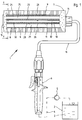
- the device shown in FIG. 1 and designated 1 is used for application of liquids, such as paint 3 on a wall, and consists in essentially from a support pipe 11 connectable to a delivery line 4, a on this rotatably arranged color distributor 21 and one on this held with a perforated support tube 8 formed from floor 9 Applicator roller 7.
- the ink 3 to be applied is removed by means of a pump 5 a reservoir 2 introduced into the conveyor tube 4, in which one with a handle piece 6 optionally shown to open the shut-off valve is inserted.
- the application roller 7 is on the Support tube 11, on which the handle 6 is fastened by means of a bracket 16, tense.
- the color distributor 21 as can be seen in particular in FIG. 2, from a triangular insert 22, which consists of a tube piece 23 and three this integrally formed projecting ribs 24 is composed.
- the ribs 24 are in this case designed as large-volume air chambers 25 which are closed at the end and on the outside each with centrally arranged molded-on contact strips 26 equipped for holding the support tube 8 of the applicator roller 7. Between Ribs 24 are thus free spaces 29, which serve as storage spaces for the color 3 to be applied.
- Pipe piece 23 of insert 22 For feeding the color to be processed into the free spaces 29 are in the Pipe piece 23 of insert 22 has axially extending recesses 27 incorporated, which together with the outer surface of the support tube 11 in this incorporated outlet openings 13 with the interior 12 of the Carrier tube 11 form connected throttle channels 28.
- radial holes 30 incorporated so that the Color 3 by the pressure built up by the pump 5 from the interior 12 of the carrier tube 11 via the outlet openings 13 into the throttle channels 28 and of these can get into the free spaces 29 through the bores 30.
- the throttle channels 28 and the free spaces 29 over the axial length of the Extend roller 8 it is always ensured that the paint to be applied 3rd the floor 9 of the application roller 7 is supplied evenly and almost without pressure.
- the paint distributor 21 and the support tube 11 are easy to clean. At from this removed color distributor 21, namely the throttle channels 28 partially delimiting recesses 27 exposed and, like that smooth support tube 11 are rinsed off. And since the insert 22 no If there are undercuts, paint residues can also be easily removed from it remove.
- the ribs 24 provided with air chambers 25 furthermore achieved that the free spaces 29 filling with color 3 have only a small volume have and the weight of the application device 1 thus low in operation can be held.
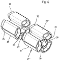
- the insert 22' '' of the Color distributor 21 '' 'composed of individual segments 31, 31' ... which are inserted into each other and by two tie rods 34 which are in the end caps 14th and 15 are supported and reach through the air chambers 25, held together become.
- the segments 31, 31 '... are this, as can be seen in particular from FIG. 6, on one Each end face with an extension 32 and on the other end face with one Provide clearance 33 that the insert 32 of the adjacent segment 31st or 31 'record.
- the holes 30 are each half in two abutting segments 31, 31 'incorporated so that the Forming the segments 31, 31 '... the holes 30 without any special Measures can be provided.
Landscapes
- Engineering & Computer Science (AREA)
- Mechanical Engineering (AREA)
- Coating Apparatus (AREA)
- Spray Control Apparatus (AREA)
Applications Claiming Priority (2)
| Application Number | Priority Date | Filing Date | Title |
|---|---|---|---|
| DE19742888A DE19742888A1 (de) | 1997-09-29 | 1997-09-29 | Auftragsvorrichtung |
| DE19742888 | 1997-09-29 |
Publications (2)
| Publication Number | Publication Date |
|---|---|
| EP0904850A2 true EP0904850A2 (fr) | 1999-03-31 |
| EP0904850A3 EP0904850A3 (fr) | 2002-01-02 |
Family
ID=7843947
Family Applications (1)
| Application Number | Title | Priority Date | Filing Date |
|---|---|---|---|
| EP98113961A Withdrawn EP0904850A3 (fr) | 1997-09-29 | 1998-07-25 | Dispositif d'application |
Country Status (4)
| Country | Link |
|---|---|
| US (1) | US6059476A (fr) |
| EP (1) | EP0904850A3 (fr) |
| JP (1) | JPH11169779A (fr) |
| DE (1) | DE19742888A1 (fr) |
Cited By (1)
| Publication number | Priority date | Publication date | Assignee | Title |
|---|---|---|---|---|
| US11950677B2 (en) | 2019-02-28 | 2024-04-09 | L'oreal | Devices and methods for electrostatic application of cosmetics |
Families Citing this family (5)
| Publication number | Priority date | Publication date | Assignee | Title |
|---|---|---|---|---|
| DE19943324B4 (de) * | 1998-09-16 | 2005-04-21 | Thomas Dietlmeier | Roller zum Auftragen von Farben oder dergleichen Auftragsmassen |
| DE10238503A1 (de) * | 2002-08-17 | 2004-02-26 | Klaus Steinhauser | Auftragungsgerät für Flüssigkeiten, insbesondere Farbe |
| US7255509B2 (en) * | 2005-07-28 | 2007-08-14 | Miguel Wang | Paint roller assembly |
| US20100014908A1 (en) * | 2008-07-18 | 2010-01-21 | Campbell Shawn O | Joint compound tool |
| US9339826B2 (en) | 2012-08-07 | 2016-05-17 | Chem-Trend L.P. | Low-profile rolling spray applicator |
Citations (1)
| Publication number | Priority date | Publication date | Assignee | Title |
|---|---|---|---|---|
| DE3719171A1 (de) | 1986-06-09 | 1987-12-10 | Graco Inc | Druckbeaufschlagte auftragrolle |
Family Cites Families (6)
| Publication number | Priority date | Publication date | Assignee | Title |
|---|---|---|---|---|
| US3826581A (en) * | 1972-08-10 | 1974-07-30 | B Henderson | Fountain liquid applicator |
| JPS5791773A (en) * | 1980-11-27 | 1982-06-08 | Kimurashin Kk | Method for sending paint to roller type painting apparatus under pressure |
| US4588318A (en) * | 1980-12-22 | 1986-05-13 | Black & Decker Inc. | Painting applicator with remote transmitter control |
| US4599009A (en) * | 1984-06-22 | 1986-07-08 | Black & Decker Inc. | Paint roller sealing system |
| DE8525264U1 (de) * | 1985-09-04 | 1985-10-17 | Lebau Elemente Lehmkuhl GmbH & Co KG, 6832 Hockenheim | Farbroller |
| JPH09192584A (ja) * | 1996-01-17 | 1997-07-29 | Fuji Heavy Ind Ltd | ローラ式塗布装置 |
-
1997
- 1997-09-29 DE DE19742888A patent/DE19742888A1/de not_active Withdrawn
-
1998
- 1998-07-25 EP EP98113961A patent/EP0904850A3/fr not_active Withdrawn
- 1998-09-11 US US09/151,929 patent/US6059476A/en not_active Expired - Fee Related
- 1998-09-28 JP JP10273690A patent/JPH11169779A/ja active Pending
Patent Citations (1)
| Publication number | Priority date | Publication date | Assignee | Title |
|---|---|---|---|---|
| DE3719171A1 (de) | 1986-06-09 | 1987-12-10 | Graco Inc | Druckbeaufschlagte auftragrolle |
Cited By (1)
| Publication number | Priority date | Publication date | Assignee | Title |
|---|---|---|---|---|
| US11950677B2 (en) | 2019-02-28 | 2024-04-09 | L'oreal | Devices and methods for electrostatic application of cosmetics |
Also Published As
| Publication number | Publication date |
|---|---|
| JPH11169779A (ja) | 1999-06-29 |
| EP0904850A3 (fr) | 2002-01-02 |
| US6059476A (en) | 2000-05-09 |
| DE19742888A1 (de) | 1999-04-01 |
Similar Documents
| Publication | Publication Date | Title |
|---|---|---|
| EP0599087B1 (fr) | Dispositif pour la lubrification et le nettoyage des chaînes et des rails | |
| EP0357538A2 (fr) | Appareil pour mettre un agent nettoyant liquide sur un tapis | |
| DD210838A5 (de) | Geraet zum auftragen fluider medien mittels kunststoffborsten und verfahren zur herstellung solcher geraete | |
| DE2529380C2 (de) | Bohrwerkzeug mit Spülungsschürze | |
| CH615329A5 (fr) | ||
| EP0045370A2 (fr) | Appareil pour la teinture partielle des cheveux | |
| EP0626141A1 (fr) | Procédé de mise en place de faisceaux de soies | |
| EP0904850A2 (fr) | Dispositif d'application | |
| DE3636013C2 (fr) | ||
| EP1749586A1 (fr) | Procédé et dispositif de régulation de la largeur et/ou de la densité d'une masse liquide | |
| DE60308956T3 (de) | Applikatoraufsatz und Vorrichtung zum Aufbewahren und Auftragen eines kosmetischen Produkts, welches einen solchen Aufsatz umfasst | |
| DE2914030A1 (de) | Anstreichrolle | |
| EP1608247B1 (fr) | Élément pour appliquer un agent capillaire cosmétique | |
| DE29714564U1 (de) | Vorrichtung zum Vernebeln von Flüssigkeiten | |
| DE19943324B4 (de) | Roller zum Auftragen von Farben oder dergleichen Auftragsmassen | |
| EP0553441B1 (fr) | Appareil pour appliquer un liquide | |
| EP2312056B1 (fr) | Dispositif de production de lignes de marquage constituées d'une multitude de portions de matériau de marquage individuelles | |
| DE8119211U1 (de) | "Applikator zum Anfärben von Haarstränen" | |
| DE9410470U1 (de) | Walzenförmiges Werkzeug für das Verteilen von Flüssigkeiten auf Flächen | |
| EP0743904B1 (fr) | Procede et dispositif de nettoyage d'applicateurs | |
| DE19937534B4 (de) | Kasten aus Kunststoff | |
| DE19700445B4 (de) | Verfahren und Vorrichtung zur Aufbringung unterschiedlichfarbiger Flocke auf Dichtungsprofile | |
| DE8628473U1 (de) | Vorrichtung zur Leimangabe an zu verleimende Holzflächen | |
| DE202004005249U1 (de) | Farbenwalze | |
| DE10163535A1 (de) | Aufnahmebehälter |
Legal Events
| Date | Code | Title | Description |
|---|---|---|---|
| PUAI | Public reference made under article 153(3) epc to a published international application that has entered the european phase |
Free format text: ORIGINAL CODE: 0009012 |
|
| AK | Designated contracting states |
Kind code of ref document: A2 Designated state(s): AT BE CH CY DE DK ES FI FR GB GR IE IT LI LU MC NL PT SE Kind code of ref document: A2 Designated state(s): DE DK ES FR GB IT NL |
|
| AX | Request for extension of the european patent |
Free format text: AL;LT;LV;MK;RO;SI |
|
| PUAL | Search report despatched |
Free format text: ORIGINAL CODE: 0009013 |
|
| AK | Designated contracting states |
Kind code of ref document: A3 Designated state(s): AT BE CH CY DE DK ES FI FR GB GR IE IT LI LU MC NL PT SE |
|
| AX | Request for extension of the european patent |
Free format text: AL;LT;LV;MK;RO;SI |
|
| 17P | Request for examination filed |
Effective date: 20020201 |
|
| GRAH | Despatch of communication of intention to grant a patent |
Free format text: ORIGINAL CODE: EPIDOS IGRA |
|
| AKX | Designation fees paid |
Free format text: DE DK ES FR GB IT NL |
|
| STAA | Information on the status of an ep patent application or granted ep patent |
Free format text: STATUS: THE APPLICATION IS DEEMED TO BE WITHDRAWN |
|
| 18D | Application deemed to be withdrawn |
Effective date: 20021219 |