EP0904850A2 - Application device - Google Patents
Application device Download PDFInfo
- Publication number
- EP0904850A2 EP0904850A2 EP98113961A EP98113961A EP0904850A2 EP 0904850 A2 EP0904850 A2 EP 0904850A2 EP 98113961 A EP98113961 A EP 98113961A EP 98113961 A EP98113961 A EP 98113961A EP 0904850 A2 EP0904850 A2 EP 0904850A2
- Authority
- EP
- European Patent Office
- Prior art keywords
- ribs
- support tube
- insert
- tube
- paint
- Prior art date
- Legal status (The legal status is an assumption and is not a legal conclusion. Google has not performed a legal analysis and makes no representation as to the accuracy of the status listed.)
- Withdrawn
Links
Images


Classifications
-
- B—PERFORMING OPERATIONS; TRANSPORTING
- B05—SPRAYING OR ATOMISING IN GENERAL; APPLYING FLUENT MATERIALS TO SURFACES, IN GENERAL
- B05C—APPARATUS FOR APPLYING FLUENT MATERIALS TO SURFACES, IN GENERAL
- B05C17/00—Hand tools or apparatus using hand held tools, for applying liquids or other fluent materials to, for spreading applied liquids or other fluent materials on, or for partially removing applied liquids or other fluent materials from, surfaces
- B05C17/02—Rollers ; Hand tools comprising coating rollers or coating endless belts
- B05C17/03—Rollers ; Hand tools comprising coating rollers or coating endless belts with feed system for supplying material from an external source or with a reservoir or container for liquid or other fluent material located in or on the hand tool outside the coating roller
- B05C17/0308—Rollers ; Hand tools comprising coating rollers or coating endless belts with feed system for supplying material from an external source or with a reservoir or container for liquid or other fluent material located in or on the hand tool outside the coating roller the liquid being supplied to the inside of the coating roller
Definitions
- the invention relates to a device for applying liquids, especially of paint on a wall, consisting of one on a conveyor line connectable support tube provided with radially directed outlet openings, a color distributor rotatably arranged on this and one on this held application roller provided with a perforated support tube.
- the color distributor is here a variety of modular Sections formed with a regular polygonal cross section, the one enclose large interior and arranged angularly next to each other are. From the interior communicating with the support tube via bores the sections clamped together by tie rods flows through the Paint to be fed through the open slots in the outer grooves of the adjacent sections and from these to the roller.
- the object of the invention is therefore a device for applying Form liquids of the aforementioned type in such a way that always satisfactory color distribution over a long period of operation is given. Furthermore, it should be achieved that a complete cleaning of the Color distributor can be made in a short time without difficulty and that only a small amount of paint has to be rinsed out. In addition, the Color distributor and thus the device in operation a low weight have so that even over a long period of fatigue-free work is made possible.
- the application device by means of which this can be accomplished is thereby characterized in that the color distributor by a over the axial length of the Carrier tube extending polygonal insert is formed from a pipe piece that can be plugged onto the carrier tube and two or more this integrally formed radially projecting ribs on which the Support tube of the applicator roller abuts that in the inner surface of the pipe section of the color distributor axially directed recesses are worked together connected to the outer surface of the support tube with its interior Form throttle channels, and that between the adjacent ribs of the Each piece has a free space for receiving the color to be processed is provided, the radially directed holes machined into the pipe section or the like. Are connected to the throttle channels.
- the ribs of the insert as the front to design sealed large-volume air chambers and the throttle channels forming recesses of the pipe section between two of these projecting ribs.
- the insert can also be made up of individual ones nested segments can be assembled, each on the one Side with offset attachments and on the other side with the Attachments of the neighboring segment containing recesses are provided, wherein the segments by means of at least two in the air chambers the ribs inserted and supported in end caps with each other connected and provided in these, the throttle channels with the free spaces connecting bores half each in two abutting segments should be incorporated.
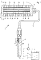
- the device shown in FIG. 1 and designated 1 is used for application of liquids, such as paint 3 on a wall, and consists in essentially from a support pipe 11 connectable to a delivery line 4, a on this rotatably arranged color distributor 21 and one on this held with a perforated support tube 8 formed from floor 9 Applicator roller 7.
- the ink 3 to be applied is removed by means of a pump 5 a reservoir 2 introduced into the conveyor tube 4, in which one with a handle piece 6 optionally shown to open the shut-off valve is inserted.
- the application roller 7 is on the Support tube 11, on which the handle 6 is fastened by means of a bracket 16, tense.
- the color distributor 21 as can be seen in particular in FIG. 2, from a triangular insert 22, which consists of a tube piece 23 and three this integrally formed projecting ribs 24 is composed.
- the ribs 24 are in this case designed as large-volume air chambers 25 which are closed at the end and on the outside each with centrally arranged molded-on contact strips 26 equipped for holding the support tube 8 of the applicator roller 7. Between Ribs 24 are thus free spaces 29, which serve as storage spaces for the color 3 to be applied.
- Pipe piece 23 of insert 22 For feeding the color to be processed into the free spaces 29 are in the Pipe piece 23 of insert 22 has axially extending recesses 27 incorporated, which together with the outer surface of the support tube 11 in this incorporated outlet openings 13 with the interior 12 of the Carrier tube 11 form connected throttle channels 28.
- radial holes 30 incorporated so that the Color 3 by the pressure built up by the pump 5 from the interior 12 of the carrier tube 11 via the outlet openings 13 into the throttle channels 28 and of these can get into the free spaces 29 through the bores 30.
- the throttle channels 28 and the free spaces 29 over the axial length of the Extend roller 8 it is always ensured that the paint to be applied 3rd the floor 9 of the application roller 7 is supplied evenly and almost without pressure.
- the paint distributor 21 and the support tube 11 are easy to clean. At from this removed color distributor 21, namely the throttle channels 28 partially delimiting recesses 27 exposed and, like that smooth support tube 11 are rinsed off. And since the insert 22 no If there are undercuts, paint residues can also be easily removed from it remove.
- the ribs 24 provided with air chambers 25 furthermore achieved that the free spaces 29 filling with color 3 have only a small volume have and the weight of the application device 1 thus low in operation can be held.
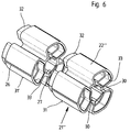
- the insert 22' '' of the Color distributor 21 '' 'composed of individual segments 31, 31' ... which are inserted into each other and by two tie rods 34 which are in the end caps 14th and 15 are supported and reach through the air chambers 25, held together become.
- the segments 31, 31 '... are this, as can be seen in particular from FIG. 6, on one Each end face with an extension 32 and on the other end face with one Provide clearance 33 that the insert 32 of the adjacent segment 31st or 31 'record.
- the holes 30 are each half in two abutting segments 31, 31 'incorporated so that the Forming the segments 31, 31 '... the holes 30 without any special Measures can be provided.
Abstract
Description
Die Erfindung bezieht sich auf eine Vorrichtung zum Auftragen von Flüssigkeiten, insbeondere von Farbe auf eine Wand, bestehend aus einem an einer Förderleitung anschließbaren mit radial gerichteten Austrittsöffnungen versehenen Trägerrohr, einem auf diesem drehbar angeordneten Farbverteiler sowie einer auf diesem gehaltenen mit einem perforierten Stützrohr versehenen Auftragswalze.The invention relates to a device for applying liquids, especially of paint on a wall, consisting of one on a conveyor line connectable support tube provided with radially directed outlet openings, a color distributor rotatably arranged on this and one on this held application roller provided with a perforated support tube.
Durch die DE 37 19 171 A1 ist eine druckbeaufschlagte Auftragswalze dieser Art bekannt. Der Farbverteiler ist hierbei durch eine Vielzahl von modulartigen Abschnitten mit jeweils regelmäßigem polygonalen Querschnitt gebildet, die einen großen Innenraum einschließen und winkelig versetzt nebeneinander angeordnet sind. Aus den über Bohrungen mit dem Trägerrohr kommunizierenden Innenraum der durch Zugstangen miteinander verspannten Abschnitte strömt die der Auftragswalze zuzuführende Farbe über seitlich offene Schlitze in Außennuten der benachbarten Abschnitte und von diesen der Walze zu.DE 37 19 171 A1 is a pressurized application roller of this type known. The color distributor is here a variety of modular Sections formed with a regular polygonal cross section, the one enclose large interior and arranged angularly next to each other are. From the interior communicating with the support tube via bores the sections clamped together by tie rods flows through the Paint to be fed through the open slots in the outer grooves of the adjacent sections and from these to the roller.
Abgesehen davon, daß der Bauaufwand dieser aus einer großen Anzahl von Bauteilen zusammengesetzten Auftragsrolle erheblich ist und die Montage der einzelnen Abschnitte einen erheblichen Zeitaufwand erfordert, ist eine zufriedenstellende Farbzuführung oftmals nicht gegeben. Die Farbe muß nämlich durch den Förderdruck durch die im Durchmesser kleinen in das Trägerrohr eingearbeiteten Bohrungen in die einzelnen Abschnitte gedrückt werden und aus deren Schlitze wiederum durch in den Seitenwänden der Abschnitte vorgesehene Bohrungen in die Außennuten der versetzt angeordneten benachbarten Abschnitte, bevor eine Einspeisung in die Walze möglich ist. Da die im Durchmesser klein bemessenen Bohrungen des Trägerrohres, die als Drosselbohrungen einen erheblichen Druckabfall hervorrufen, im Betrieb oftmals nach kurzer Zeit verstopfen, ist es vielfach unvermeidbar, daß einzelne Abschnitte unzureichend mit Farbe versorgt werden und somit keine gute Farbverteilung gegeben ist. Vor allem aber ist in diesem Zusammenhang von Nachteil, daß durch die verwinkelte Ausgestaltung des Farbverteilers dieser nur unter Schwierigkeiten mit einem erheblichen Zeitaufwand zu reinigen und daß dabei, bedingt durch den großen Innenraum, ein erheblicher Farbverlust in Kauf zu nehmen ist. Und da die Auftragsvorrichtung durch die Bauteile des Farbverteilers sowie durch Farbe gänzlich ausgefüllt ist, weist die bekannte Auftragsvorrichtung ein hohes Eigengewicht auf, so daß diese auch schwierig zu handhaben ist.In addition to the fact that the construction of this from a large number of Components composite order role is significant and the assembly of the individual sections requires a considerable amount of time is one satisfactory ink supply is often not given. The color has to be through the delivery pressure through the small diameter in the carrier tube machined holes in the individual sections and pressed out the slots of which in turn are provided in the side walls of the sections Bores in the outer grooves of the staggered adjacent sections, before it can be fed into the roller. Because it's small in diameter dimensioned bores of the support tube, which as a throttle bores cause considerable pressure drop, often clog after a short time during operation, it is often unavoidable that individual sections are inadequate with color are supplied and thus there is no good color distribution. But most of all is disadvantageous in this context that due to the angular design of the color distributor this is difficult with a significant Time to clean and that, due to the large interior, a considerable loss of color is accepted. And since the application device through the components of the paint distributor as well as completely filled with paint, the known application device on a high weight, so that this too is difficult to handle.
Aufgabe der Erfindung ist es demnach, eine Vorrichtung zum Auftragen von Flüssigkeiten der vorgenannten Gattung in der Weise auszubilden, daß eine stets zufriedenstellende Farbverteilung über einen längeren Betriebszeitraum gegeben ist. Des weiteren soll erreicht werden, daß eine vollständige Reinigung des Farbverteilers ohne Schwierigkeiten in kurzer Zeit vorgenommen werden kann und daß dabei nur eine geringe Restmenge an Farbe auszuspülen ist. Außerdem soll der Farbverteiler und damit die Vorrichtung im Betrieb ein geringes Eigengewicht aufweisen, so daß auch über einen langen Zeitraum ein ermüdungsfreies Arbeiten ermöglicht wird.The object of the invention is therefore a device for applying Form liquids of the aforementioned type in such a way that always satisfactory color distribution over a long period of operation is given. Furthermore, it should be achieved that a complete cleaning of the Color distributor can be made in a short time without difficulty and that only a small amount of paint has to be rinsed out. In addition, the Color distributor and thus the device in operation a low weight have so that even over a long period of fatigue-free work is made possible.
Die Auftragsvorrichtung, mittels der dies zu bewerkstelligen ist, ist dadurch gekennzeichnet, daß der Farbverteiler durch ein sich über die axiale Länge des Trägerrohres erstreckendes mehreckig geformtes Einsatzstück gebildet ist, das aus einem auf dem Trägerrohr aufsteckbaren Rohrstück und zwei oder mehreren an diesem angeformten radial abstehenden Rippen zusammengesetzt ist, an denen das Stützrohr der Auftragswalze anliegt, daß in die Innenmantelfläche des Rohrstückes des Farbverteilers axial gerichtete Ausnehmungen eingearbeit sind, die zusammen mit der Außenmantelfläche des Trägerrohres mit dessen Innenraum verbundene Drosselkanäle bilden, und daß zwischen den benachbarten Rippen des Einsatsstückes jeweils ein Freiraum zur Aufnahme der zu verarbeitenden Farbe vorgesehen ist, die über in das Rohrstück eingearbeitete radial gerichtete Bohrungen oder dgl. mit den Drosselkanälen verbunden sind.The application device by means of which this can be accomplished is thereby characterized in that the color distributor by a over the axial length of the Carrier tube extending polygonal insert is formed from a pipe piece that can be plugged onto the carrier tube and two or more this integrally formed radially projecting ribs on which the Support tube of the applicator roller abuts that in the inner surface of the pipe section of the color distributor axially directed recesses are worked together connected to the outer surface of the support tube with its interior Form throttle channels, and that between the adjacent ribs of the Each piece has a free space for receiving the color to be processed is provided, the radially directed holes machined into the pipe section or the like. Are connected to the throttle channels.
Zweckmäßig ist es hierbei, die Rippen des Einsatzstückes als stirnseitig verschlossene großvolumige Luftkammern zu gestalten und die die Drosselkanäle bildenden Ausnehmungen des Rohrstückes jeweils zwischen zwei von diesem abstehenden Rippen anzuordnen.It is useful here, the ribs of the insert as the front to design sealed large-volume air chambers and the throttle channels forming recesses of the pipe section between two of these projecting ribs.
Nach einer Ausführungsvariante kann das Einsatzstück auch aus einzelnen ineinandersteckbaren Segmenten zusammengesetzt sein, die jeweils auf der einen Seite mit abgesetzten Ansatzstücken und auf der anderen Seite mit die Ansatzstücke des benachbarten Segmentes aufnehmenden Freisparungen versehen sind, wobei die Segmente mittels mindestens zweier in die Luftkammern der Rippen eingesetzter und in Endkappen abgestützter Zugstangen miteinander verbunden und die in diesen vorgesehenen, die Drosselkanäle mit den Freiräumen verbindenden Bohrungen jeweils zur Hälfte in zwei aneinanderstoßende Segmente eingearbeitet sein sollten.According to one embodiment variant, the insert can also be made up of individual ones nested segments can be assembled, each on the one Side with offset attachments and on the other side with the Attachments of the neighboring segment containing recesses are provided, wherein the segments by means of at least two in the air chambers the ribs inserted and supported in end caps with each other connected and provided in these, the throttle channels with the free spaces connecting bores half each in two abutting segments should be incorporated.
Wird eine Vorrichtung zum Auftragen von Flüssigkeiten gemäß der Erfindung ausgebildet, so ist stets gewährleistet, daß die Auftragswalze auf ihrer gesamten Länge ausreichend mit Farbe versorgt wird, da sich die Drosselkanäle über die Länge des Trägerrohres erstrecken und die zwischen den einzelnen Rippen vorgesehenen als Vorratsraum wirksamen Freiräume unmittelbar miteinander verbunden sind. Selbst wenn die eine oder andere Austrittsöffnung des Trägerrohres verstopft sein sollte, ist dennoch eine ausreichende Versorgung der Freiräume und somit der Auftragswalze mit Farbe sichergestellt.Becomes a liquid application device according to the invention trained, it is always ensured that the applicator roller on its entire Sufficient length is supplied with paint, since the throttle channels extend over the Length of the support tube and between the individual ribs provided free spaces effective as storage space directly with each other are connected. Even if one or the other outlet opening of the support tube should be congested, there is still an adequate supply of free spaces and thus ensuring the application roller with paint.
Vor allem aber ist von Vorteil, daß die Reinigung des Farbverteilers auf sehr einfache Weise zu bewerkstelligen ist. Da die Drosselkanäle durch das Einsatzstück und das Trägerrohr begrenzt sind, werden durch Herausnehmen des Einsatzstückes die in dieses eingearbeiteten Ausnehmungen freigelegt, diese und auch die Freiräume können somit problemlos von Farbe gereinigt werden. Durch die als großvolumige Luftkammern ausgebildeten Rippen ist dabei nicht nur von Vorteil, daß die in dem Farbverteiler verbliebene Farbrestmenge gering ist, sondern durch die Luftkammer wird auch das Gewicht der Auftragsvorrichtung beim Auftragen von Farbe, da von dieser lediglich die Freiräume ausgefüllt werden, in einem erheblichen Maße reduziert. Die vorschlagsgemäß ausgebildete Auftragsvorrichtung ist demnach auch über einen langen Zeitraum, ohne zu ermüden, einsetzbar und einfach zu warten.Above all, however, it is advantageous that the cleaning of the paint distributor is very easy is easy to do. Because the throttle channels through the insert and the support tube are limited by removing the insert the exposed recesses in this, this and also the Free spaces can thus be easily cleaned of paint. Through the as large-volume air chambers trained ribs is not only advantageous that the remaining amount of color remaining in the color distributor is small, but due to the Air chamber is also the weight of the applicator when applying Color, since this only fills the free spaces in a considerable amount Reduced dimensions. The application device designed according to the proposal is accordingly can also be used over a long period of time without tiring, and is easy to use waiting.
In der Zeichnung ist ein Ausführungsbeispiel der erfindungsgemäß ausgebildeten Vorrichtung zum Auftragen von Flüssigkeiten dargestellt, das nachfolgend im einzelnen erläutert ist. Hierbei zeigt:
Figur 1- die an einer Farbförderleitung angeschlossene Auftragsvorrichtung, in einem Längsschnitt,
Figur 2- einen Schnitt nach der Linie II - II der
Figur 1, Figuren 3 und 4- unterschiedliche Ausgestaltungen des bei der Auftragsvorrichtung
nach
Figur 1 vorgesehenen Farbverteilers, in Schnittdarstellungen nachFigur 2, Figur 5- eine Ausführungsvariante des bei der Auftragsvorrichtung
nach
Figur 1 vorgesehenen Farbverteilers, in einem Axialschnitt, und Figur 6- den Farbverteiler nach
Figur 5, in einer perspektivischen Darstellung.
- Figure 1
- the applicator connected to a paint feed line, in a longitudinal section,
- Figure 2
- 2 shows a section along the line II-II of FIG. 1,
- Figures 3 and 4
- different configurations of the color distributor provided in the application device according to FIG. 1, in sectional representations according to FIG. 2,
- Figure 5
- an embodiment of the color distributor provided in the application device according to Figure 1, in an axial section, and
- Figure 6
- the color distributor according to Figure 5, in a perspective view.
Die in Figur 1 dargestellte und mit 1 bezeichnete Vorrichtung dient zum Auftragen
von Flüssigkeiten, beispielsweise von Farbe 3 auf einer Wand, und besteht im
wesentlichen aus einem an eine Förderleitung 4 anschließbare Trägerrohr 11, einem
auf diesem drehbar angeordneten Farbverteiler 21 sowie einem auf diesem
gehaltenen mit einem perforierten Stützrohr 8 versehenen aus Floor 9 gebildeten
Auftragswalze 7. Die aufzutragende Farbe 3 wird hierbei mittels einer Pumpe 5 aus
einem Vorratsbehälter 2 in das Förderrohr 4 eingebracht, in das ein mit einem nicht
dargestellten wahlweise zu öffnenden Absperrventil ausgestattetes Griffstück 6
eingesetzt ist. Mittels Endkappen 14 und 15 ist die Auftragswalze 7 auf dem
Trägerrohr 11, an dem mittels eines Bügels 16 das Griffstück 6 befestigt ist,
verspannt.The device shown in FIG. 1 and designated 1 is used for application
of liquids, such as
Der Farbverteiler 21 besteht, wie dies insbesondere der Figur 2 zu entnehmen ist,
aus einem dreieckigen Einsatzstück 22, das aus einem Rohrstück 23 und drei an
diesem angeformten abstehenden Rippen 24 zusammengesetzt ist. Die Rippen 24
sind hierbei als großvolumige stirnseitig verschlossene Luftkammern 25 ausgebildet
und auf den Außenseiten jeweils mit mittig angeordneten angeformten Anlageleisten
26 zur Halterung des Stützrohres 8 der Auftragswalze 7 ausgestattet. Zwischen den
Rippen 24 sind somit Freiräume 29 geschaffen, die als Vorratsräume für die
aufzutragende Farbe 3 dienen.The
Zur Zuführung der zu verarbeitenden Farbe in die Freiräume 29 sind in das
Rohrstück 23 des Einsatzstückes 22 axial verlaufende Ausnehmungen 27
eingearbeitet, die zusammen mit der Außenmantelfläche des Trägerrohres 11 über
in dieses eingearbeitete Austrittsöffnungen 13 mit dem Innenraum 12 des
Trägerrohres 11 verbundene Drosselkanäle 28 bilden. Außerdem sind zwischen den
Rippen 24 in das Rohrstück 23 radiale Bohrungen 30 eingearbeitet, so daß die
Farbe 3 durch den von der Förderpunpe 5 aufgebauten Druck aus dem Innenraum
12 des Trägerrohres 11 über die Austrittsöffnungen 13 in die Drosselkanäle 28 und
von diesen durch die Bohrungen 30 in die Freiräume 29 gelangen kann.For feeding the color to be processed into the
Da sich die Drosselkanäle 28 und die Freiräume 29 über die axiale Länge der
Auftragswalze 8 erstrecken, ist stets gewährleistet, daß die aufzutragende Farbe 3
gleichmäßig und nahezu drucklos dem Floor 9 der Auftragswalze 7 zugeführt wird.
Außerdem sind der Farbverteiler 21 und das Trägerrohr 11 leicht zu reinigen. Bei
von diesem abgenommenem Farbverteiler 21 sind nämlich die die Drosselkanäle 28
teilweise begrenzenden Ausnehmungen 27 freigelegt und können, wie auch das
glatte Trägerrohr 11, abgespült werden. Und da das Einsatzstück 22 keine
Hinterschneidungen aufweist, sind von diesem ebenfalls problemlos Farbreste zu
entfernen. Durch die mit Luftkammern 25 versehenen Rippen 24 wird ferner
erreicht, daß die sich mit Farbe 3 füllenden Freiräume 29 nur ein geringes Volumen
aufweisen und das Eigengewicht der Auftragsvorrichtung 1 somit im Betrieb gering
gehalten werden kann.Since the
Bei den Ausführungsvarianten nach den Figuren 3 und 4 sind die Einsatzstücke 22'
bzw. 22'' der Farbverteiler 21' bzw. 21'' mit zwei bzw. fünf an den Rohrstücken 23
angeformten Rippen 24' bzw. 24'' versehen. Auf diese Weise kann je nach
Einsatzzweck der Auftragsvorrichtung 1 die Größe der zwischen den Rippen 24'
bzw. 24'' vorgesehenen Freiräume 29' bzw. 29'' variiert werden.In the embodiment variants according to FIGS. 3 and 4, the insert pieces 22 'are
or 22 ″ of the
Bei der Auftragsvorrichtung 1' nach Figur 5 ist das Einsatzstück 22''' des
Farbverteilers 21''' aus einzelnen Segmengen 31, 31' ... zusamengesetzt, die
ineinander gesteckt sind und durch zwei Zugstangen 34, die in den Endkappen 14
und 15 abgestützt sind und die Luftkammern 25 durchgreifen, zusammengehalten
werden. Zum flüssigkeitsdichten Zusammenfügen der Segmente 31, 31' ... sind
diese, wie dies insbesondere auch der Figur 6 zu entnehmen ist, auf der einen
Stirnseite jeweils mit einem Ansatzstück 32 und auf der anderen Stirnseite mit einer
Freisparung 33 versehen, die das Einsatzstück 32 des benachbarten Segmentes 31
bzw. 31' aufnehmen. Außerdem sind hierbei die Bohrungen 30 jeweils zur Hälfte in
zwei aneinanderstoßende Segmente 31, 31' eingearbeitet, so daß bei der
Ausformung der Segmente 31, 31' ... die Bohrungen 30 ohne besondere
Maßnahmen mit vorgesehen werden können.In the application device 1 'according to FIG. 5, the insert 22' '' of the
Color distributor 21 '' 'composed of
Claims (7)
dadurch gekennzeichnet,
characterized,
dadurch gekennzeichnet,
characterized,
dadurch gekennzeichnet,
characterized,
Ansprüche 1 bis 3,
dadurch gekennzeichnet,
Claims 1 to 3,
characterized,
dadurch gekennzeichnet,
characterized,
dadurch gekennzeichnet,
characterized,
der Ansprüche 1 bis 6,
dadurch gekennzeichnet,
of claims 1 to 6,
characterized,
Applications Claiming Priority (2)
| Application Number | Priority Date | Filing Date | Title |
|---|---|---|---|
| DE19742888A DE19742888A1 (en) | 1997-09-29 | 1997-09-29 | Application device |
| DE19742888 | 1997-09-29 |
Publications (2)
| Publication Number | Publication Date |
|---|---|
| EP0904850A2 true EP0904850A2 (en) | 1999-03-31 |
| EP0904850A3 EP0904850A3 (en) | 2002-01-02 |
Family
ID=7843947
Family Applications (1)
| Application Number | Title | Priority Date | Filing Date |
|---|---|---|---|
| EP98113961A Withdrawn EP0904850A3 (en) | 1997-09-29 | 1998-07-25 | Application device |
Country Status (4)
| Country | Link |
|---|---|
| US (1) | US6059476A (en) |
| EP (1) | EP0904850A3 (en) |
| JP (1) | JPH11169779A (en) |
| DE (1) | DE19742888A1 (en) |
Cited By (1)
| Publication number | Priority date | Publication date | Assignee | Title |
|---|---|---|---|---|
| US11950677B2 (en) | 2019-02-28 | 2024-04-09 | L'oreal | Devices and methods for electrostatic application of cosmetics |
Families Citing this family (5)
| Publication number | Priority date | Publication date | Assignee | Title |
|---|---|---|---|---|
| DE19943324B4 (en) * | 1998-09-16 | 2005-04-21 | Thomas Dietlmeier | Roller for applying paints or the like application masses |
| DE10238503A1 (en) * | 2002-08-17 | 2004-02-26 | Klaus Steinhauser | Application appliance as paint roller has paint drawn from inside of appliance in controlled manner through handle and especially through suction pipe running through it |
| US7255509B2 (en) * | 2005-07-28 | 2007-08-14 | Miguel Wang | Paint roller assembly |
| US20100014908A1 (en) * | 2008-07-18 | 2010-01-21 | Campbell Shawn O | Joint compound tool |
| US9339826B2 (en) | 2012-08-07 | 2016-05-17 | Chem-Trend L.P. | Low-profile rolling spray applicator |
Citations (1)
| Publication number | Priority date | Publication date | Assignee | Title |
|---|---|---|---|---|
| DE3719171A1 (en) | 1986-06-09 | 1987-12-10 | Graco Inc | PRESSURIZED ORDER ROLL |
Family Cites Families (6)
| Publication number | Priority date | Publication date | Assignee | Title |
|---|---|---|---|---|
| US3826581A (en) * | 1972-08-10 | 1974-07-30 | B Henderson | Fountain liquid applicator |
| JPS5791773A (en) * | 1980-11-27 | 1982-06-08 | Kimurashin Kk | Method for sending paint to roller type painting apparatus under pressure |
| US4588318A (en) * | 1980-12-22 | 1986-05-13 | Black & Decker Inc. | Painting applicator with remote transmitter control |
| US4599009A (en) * | 1984-06-22 | 1986-07-08 | Black & Decker Inc. | Paint roller sealing system |
| DE8525264U1 (en) * | 1985-09-04 | 1985-10-17 | Lebau Elemente Lehmkuhl GmbH & Co KG, 6832 Hockenheim | Paint roller |
| JPH09192584A (en) * | 1996-01-17 | 1997-07-29 | Fuji Heavy Ind Ltd | Roller type coating device |
-
1997
- 1997-09-29 DE DE19742888A patent/DE19742888A1/en not_active Withdrawn
-
1998
- 1998-07-25 EP EP98113961A patent/EP0904850A3/en not_active Withdrawn
- 1998-09-11 US US09/151,929 patent/US6059476A/en not_active Expired - Fee Related
- 1998-09-28 JP JP10273690A patent/JPH11169779A/en active Pending
Patent Citations (1)
| Publication number | Priority date | Publication date | Assignee | Title |
|---|---|---|---|---|
| DE3719171A1 (en) | 1986-06-09 | 1987-12-10 | Graco Inc | PRESSURIZED ORDER ROLL |
Cited By (1)
| Publication number | Priority date | Publication date | Assignee | Title |
|---|---|---|---|---|
| US11950677B2 (en) | 2019-02-28 | 2024-04-09 | L'oreal | Devices and methods for electrostatic application of cosmetics |
Also Published As
| Publication number | Publication date |
|---|---|
| EP0904850A3 (en) | 2002-01-02 |
| US6059476A (en) | 2000-05-09 |
| JPH11169779A (en) | 1999-06-29 |
| DE19742888A1 (en) | 1999-04-01 |
Similar Documents
| Publication | Publication Date | Title |
|---|---|---|
| EP0599087B1 (en) | Device for lubricating and cleaning of chains and rails | |
| EP0357538A2 (en) | Apparatus for applying liquid detergents to a carpet | |
| DD210838A5 (en) | APPARATUS FOR APPLYING FLUIDER MEDIA USING PLASTIC BRISTLES AND METHOD FOR PRODUCING SUCH DEVICES | |
| DE2529380C2 (en) | Drilling tool with flushing apron | |
| CH615329A5 (en) | ||
| EP0626141A1 (en) | Method of setting bundles of bristles | |
| EP0045370A2 (en) | Apparatus for partially dying the hair | |
| EP0904850A2 (en) | Application device | |
| DE3636013C2 (en) | ||
| DE3145151C2 (en) | Drivable roller for grinding or polishing the surface of a vehicle body or the like | |
| DE60308956T3 (en) | Applicator attachment and device for storing and applying a cosmetic product comprising such an attachment | |
| DE2914030A1 (en) | Hollow paint roller supplied by paint pump - has hollow handle with valve at one end and supply tube connection at other end | |
| EP1608247B1 (en) | Attachment for applying a hair cosmetic agent | |
| EP1839874B1 (en) | System for servicing cartridges of inkjet printers | |
| EP0553441B1 (en) | Device for applying a liquid | |
| EP0638721A1 (en) | Feed pump | |
| EP2312056B1 (en) | Device for producing marking lines composed of several individual marking material portions | |
| DE19943324B4 (en) | Roller for applying paints or the like application masses | |
| DE8119211U1 (en) | "Applicator for coloring hair strands" | |
| EP0743904B1 (en) | Process and device for cleaning applicators | |
| WO2000002466A2 (en) | Device for the partial colouring of hair | |
| DE19937534B4 (en) | Plastic box | |
| DE19700445B4 (en) | Method and device for applying differently colored flake to sealing profiles | |
| DE202004005249U1 (en) | Paint roller has plastics handle connectable to plastics support part which has two extending support arms with support shafts and wheels to fit into hollow roller | |
| DE10163535A1 (en) | Industrial spray paint container has return-feed via top-mounted circular distribution channel |
Legal Events
| Date | Code | Title | Description |
|---|---|---|---|
| PUAI | Public reference made under article 153(3) epc to a published international application that has entered the european phase |
Free format text: ORIGINAL CODE: 0009012 |
|
| AK | Designated contracting states |
Kind code of ref document: A2 Designated state(s): AT BE CH CY DE DK ES FI FR GB GR IE IT LI LU MC NL PT SE Kind code of ref document: A2 Designated state(s): DE DK ES FR GB IT NL |
|
| AX | Request for extension of the european patent |
Free format text: AL;LT;LV;MK;RO;SI |
|
| PUAL | Search report despatched |
Free format text: ORIGINAL CODE: 0009013 |
|
| AK | Designated contracting states |
Kind code of ref document: A3 Designated state(s): AT BE CH CY DE DK ES FI FR GB GR IE IT LI LU MC NL PT SE |
|
| AX | Request for extension of the european patent |
Free format text: AL;LT;LV;MK;RO;SI |
|
| 17P | Request for examination filed |
Effective date: 20020201 |
|
| GRAH | Despatch of communication of intention to grant a patent |
Free format text: ORIGINAL CODE: EPIDOS IGRA |
|
| AKX | Designation fees paid |
Free format text: DE DK ES FR GB IT NL |
|
| STAA | Information on the status of an ep patent application or granted ep patent |
Free format text: STATUS: THE APPLICATION IS DEEMED TO BE WITHDRAWN |
|
| 18D | Application deemed to be withdrawn |
Effective date: 20021219 |