EP0904849A2 - Verfahren und Klebstoffsdüsen zum Besprühen eines Substrats mit Klebstoff nach einem Muster - Google Patents
Verfahren und Klebstoffsdüsen zum Besprühen eines Substrats mit Klebstoff nach einem Muster Download PDFInfo
- Publication number
- EP0904849A2 EP0904849A2 EP98307447A EP98307447A EP0904849A2 EP 0904849 A2 EP0904849 A2 EP 0904849A2 EP 98307447 A EP98307447 A EP 98307447A EP 98307447 A EP98307447 A EP 98307447A EP 0904849 A2 EP0904849 A2 EP 0904849A2
- Authority
- EP
- European Patent Office
- Prior art keywords
- fluid
- die assembly
- fluid dispensing
- dispensing orifices
- die
- Prior art date
- Legal status (The legal status is an assumption and is not a legal conclusion. Google has not performed a legal analysis and makes no representation as to the accuracy of the status listed.)
- Granted
Links
- 239000000853 adhesive Substances 0.000 title claims description 50
- 230000001070 adhesive effect Effects 0.000 title claims description 50
- 238000000034 method Methods 0.000 title abstract description 18
- 239000007921 spray Substances 0.000 title description 6
- 239000012530 fluid Substances 0.000 claims abstract description 286
- 230000000712 assembly Effects 0.000 claims abstract description 86
- 238000000429 assembly Methods 0.000 claims abstract description 86
- 239000000758 substrate Substances 0.000 claims abstract description 81
- 239000011800 void material Substances 0.000 claims abstract description 50
- 230000010355 oscillation Effects 0.000 claims abstract description 20
- 239000004831 Hot glue Substances 0.000 claims abstract description 5
- 230000007423 decrease Effects 0.000 claims abstract 5
- 230000003247 decreasing effect Effects 0.000 claims description 7
- 238000005507 spraying Methods 0.000 claims description 5
- 238000003491 array Methods 0.000 description 4
- 238000013459 approach Methods 0.000 description 3
- 230000000903 blocking effect Effects 0.000 description 3
- 210000001124 body fluid Anatomy 0.000 description 3
- 238000004519 manufacturing process Methods 0.000 description 3
- 206010021639 Incontinence Diseases 0.000 description 2
- 238000004891 communication Methods 0.000 description 2
- 239000002313 adhesive film Substances 0.000 description 1
- 239000012790 adhesive layer Substances 0.000 description 1
- 230000000295 complement effect Effects 0.000 description 1
- 238000005553 drilling Methods 0.000 description 1
- 230000000694 effects Effects 0.000 description 1
- 238000003780 insertion Methods 0.000 description 1
- 230000037431 insertion Effects 0.000 description 1
- 239000010410 layer Substances 0.000 description 1
- 239000000463 material Substances 0.000 description 1
Images
Classifications
-
- B—PERFORMING OPERATIONS; TRANSPORTING
- B05—SPRAYING OR ATOMISING IN GENERAL; APPLYING FLUENT MATERIALS TO SURFACES, IN GENERAL
- B05B—SPRAYING APPARATUS; ATOMISING APPARATUS; NOZZLES
- B05B1/00—Nozzles, spray heads or other outlets, with or without auxiliary devices such as valves, heating means
- B05B1/14—Nozzles, spray heads or other outlets, with or without auxiliary devices such as valves, heating means with multiple outlet openings; with strainers in or outside the outlet opening
- B05B1/16—Nozzles, spray heads or other outlets, with or without auxiliary devices such as valves, heating means with multiple outlet openings; with strainers in or outside the outlet opening having selectively- effective outlets
-
- B—PERFORMING OPERATIONS; TRANSPORTING
- B05—SPRAYING OR ATOMISING IN GENERAL; APPLYING FLUENT MATERIALS TO SURFACES, IN GENERAL
- B05C—APPARATUS FOR APPLYING FLUENT MATERIALS TO SURFACES, IN GENERAL
- B05C5/00—Apparatus in which liquid or other fluent material is projected, poured or allowed to flow on to the surface of the work
- B05C5/02—Apparatus in which liquid or other fluent material is projected, poured or allowed to flow on to the surface of the work the liquid or other fluent material being discharged through an outlet orifice by pressure, e.g. from an outlet device in contact or almost in contact, with the work
- B05C5/027—Coating heads with several outlets, e.g. aligned transversally to the moving direction of a web to be coated
-
- Y—GENERAL TAGGING OF NEW TECHNOLOGICAL DEVELOPMENTS; GENERAL TAGGING OF CROSS-SECTIONAL TECHNOLOGIES SPANNING OVER SEVERAL SECTIONS OF THE IPC; TECHNICAL SUBJECTS COVERED BY FORMER USPC CROSS-REFERENCE ART COLLECTIONS [XRACs] AND DIGESTS
- Y10—TECHNICAL SUBJECTS COVERED BY FORMER USPC
- Y10T—TECHNICAL SUBJECTS COVERED BY FORMER US CLASSIFICATION
- Y10T156/00—Adhesive bonding and miscellaneous chemical manufacture
- Y10T156/17—Surface bonding means and/or assemblymeans with work feeding or handling means
- Y10T156/1798—Surface bonding means and/or assemblymeans with work feeding or handling means with liquid adhesive or adhesive activator applying means
Definitions
- the invention relates generally to systems and methods for dispensing fluids onto moving substrates, and more particularly to adhesive dispensing nozzle configurations for dispensing adhesives in partial spray patterns for partially covering a substrate, and still more particularly to meltblown adhesive dispensing systems including a manifold that supplies adhesive to a plurality meltblowing die assemblies configured for partially covering a substrate with adhesive.
- Adhesives are used, for example, to bond overlapping substrate layers in the production of a variety of bodily fluid absorbing hygienic articles, including disposable diapers and incontinence pads, sanitary napkins, patient underlays, and surgical dressings.
- Known systems include generally a plurality of adhesive dispensing spray nozzles arranged in one or more arrays extending across a moving substrate for applying an adhesive layer or film thereon.
- Other systems include one or more die assemblies having a plurality of adhesive dispensing orifices arranged in an array, wherein the die assemblies are sometimes arrangeable side by side to extend the array lengthwise.
- EP-A- (application No. 98302718.6) discloses a plurality of meltblowing die assemblies, or nozzles, mountable side by side on one or both ends of a common manifold, or head, which provides a metered supply of adhesive to each die assembly.
- the die assemblies each comprise a plurality of substantially parallel plate members forming an array of adhesive dispensing orifices on a dispensing surface thereof.
- the array of fluid dispensing orifices of each die assembly compose a section of a longer array formed by the plurality of adjacent die assemblies disposed along a common end of the manifold.
- One or both sides of the manifold may be mounted adjacent the side of a similarly configured manifold to form still longer arrays of fluid dispensing orifices, thereby providing a modular meltblowing adhesive dispensing system that accommodates substrates having any dimensional width.
- the adhesive is applied to cover the full width of the substrate, and in other applications it is desirable to apply the adhesive to cover only select portions of the substrate leaving other portions thereof without adhesive coverage.
- it is desirable to film different sized areas of adhesive noncoverage which may correspond to cut away areas thereof or may be designated for insertion of an elastic band.
- the areas of adhesive noncoverage may be as narrow as one-eighth of an inch or less and may be as wide as one or many inches, depending on the particular application requirements.
- the side by side arrangement of die assemblies does not provide consistent spacing between the fluid dispensing orifices thereof, evidenced by a gap between the orifices of adjacent die assemblies, suggesting that adhesive coverage on the substrate is not continuous, or at least not uniform, particularly in areas between adjacent die assemblies void of fluid dispensing orifices.
- the selective interruption of adhesive supplied to one or more die assemblies to form areas of adhesive non-coverage limits the corresponding gaps or areas of non-coverage to the width of the die assembly to which fluid flow is interrupted, and more generally in proportion to multiples of the spray pattern width corresponding thereto, provided the system comprises several die assemblies having the same width.
- the meltblowing die assemblies are one inch wide (2.5mm), and generally produce a substantially correspondingly wide spray pattern on the substrate.
- Some adhesive dispensing manifolds are configured with an array of adhesive dispensing nozzles on opposing end portions thereof, wherein the array of die assemblies on one end of the manifold are offset relative to the array of die assemblies on the other end of the manifold.
- the offset is usually one-half the width of the die assembly.
- the gap or area of adhesive non-coverage may thus be reduced to a dimension corresponding to the amount of offset upon interruption of fluid flow to overlapping die assemblies on opposing ends of the manifold. But this approach continues to limit the area of adhesive non-coverage in proportion to multiples of the offset between die assemblies, which is fixed.
- the present invention is drawn toward advancements in the art of dispensing fluids onto moving substrates that overcome problems in the prior art economically.
- a system for applying fluids including fiberized adhesives onto a substrate from at least one die assembly mounted on a mounting surface of a manifold that supplies fluid to the at least one die assembly the at least one die assembly is selected from a group comprising
- a system for applying fluids including fiberized adhesives onto a substrate comprises a manifold having a mounting surface on which at least one die assembly is mountable, the manifold supplying fluid to the at least one die assembly;
- a method for applying fluids including fiberized adhesives onto a substrate comprises:
- each of the plurality of fluid dispensing orifices of the first die assembly flanked by an air dispensing orifice disposed on opposing sides of the fluid dispensing orifice, the method further comprising dispensing air from air dispensing orifices disposed on at least a portion of the remaining first portion of the first die assembly void of fluid dispensing orifices.
- each of the plurality of fluid dispensing orifices of the first die assembly flanked by an air dispensing orifice disposed on opposing sides of the fluid dispensing orifice, the method further comprising decreasing an oscillation amplitude of fluid dispensed from fluid dispensing orifices toward at least one endmost fluid dispensing orifice defining an interface between areas of fluid coverage and non-coverage on the substrate, whereby fluid dispensed from the at least one endmost fluid dispensing orifice has a smallest oscillation amplitude.
- the method may further comprise:
- the method may further comprise: supplying fluid to at least first and second die assemblies mounted on the mounting surface of the manifold;
- the method further comprises: supplying fluid to at least first, second and third die assemblies mounted on the mounting surface of the manifold;
- a method for applying fluids including fiberized adhesives onto a substrate comprises:
- the method further comprises:
- a method for applying fluids including fiberized adhesives onto a substrate comprises:
- a method for applying fluids including fiberized adhesives onto a substrate comprises: supplying fluid to at least one die assembly mounted on a mounting surface of a manifold;
- the method further comprises decreasing an oscillation amplitude of fluid dispensed from fluid dispensing orifices toward at least one endmost fluid dispensing orifice defining an interface between areas of fluid coverage and noncoverage on the substrate, whereby fluid dispensed from the at least one endmost fluid dispensing orifice has a smallest oscillation amplitude.
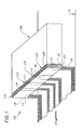
- FIG. 1 is a system 100 for applying fluids including fiberized adhesives onto a substrate S, which in the exemplary embodiment is a material used in the manufacture of bodily fluid absorbing hygienic articles, including disposable diapers and incontinence pads, sanitary napkins, patient underlays, and surgical dressings.
- the invention is more generally applicable to selectively applying fluids to portions of any substrate.
- the system 100 comprises generally a plurality of die assemblies 110-116 mountable side by side on a common manifold 120, or head, and more particularly on one or both ends 122 thereof, which provides a metered supply of adhesive thereto, whereby the die assemblies and manifold form a modular assembly as disclosed more fully in EP-A-(application No. 98302718.6) . In other embodiments, however, one or more die assemblies are mounted onto the manifold.
- the plurality of die assemblies 110 of the exemplary embodiments each include a plurality of fluid dispensing orifices 12 disposed on a dispensing surface 14 thereof.
- the fluid dispensing orifices 12 are arranged at least partially across a width extending from a right side 16 of the die assembly to a left side 18 thereof.
- the die assemblies of the exemplary embodiments are, more particularly, meltblowing die assemblies, or nozzles, mountable on a manifold to form a modular assembly useable for dispensing or spraying fiberized hot melt adhesives onto substrates.
- the meltblowing die assemblies of this preferred exemplary type each comprise generally a plurality of laminated members, or plates, defining the plurality of fluid dispensing orifices 12 as disclosed more fully in EP-A-0835952 and in EP-A- (application No. 98302718.6) .
- the die assemblies 110 may alternatively be of the type disclosed in US-A-5,421,941 wherein the orifices are formed by precision drilling operations, among other types of die assemblies mountable onto a manifold to form a modular assembly.
- the plurality of die assemblies 110-116 are mountable on a common mounting surface 122 of the manifold 120 to form the modular assembly. And in a related preferred embodiment, the plurality of die assemblies are arranged on the manifold 120 so that the plurality of fluid dispensing orifices 12 thereof form not more than a single substantially linear array of fluid dispensing orifices.
- the single substantially linear array of fluid dispensing orifices may however be piece-wise linear insofar as the invention is directed toward partially covering the substrate S with fluids dispensed from die assemblies 110 having fluid dispensing orifices selectively disposed on or across portions thereof and not on other remaining portions thereof as discussed further below.
- die assemblies positioned adjacently on the manifold 120 are preferably configured generally to provide a substantially continuous, or seamless, application of fluid onto the substrate, except in areas of the substrate where adhesive non-coverage is desired.
- the plurality of die assemblies be arranged to form one or more arrays of fluid dispensing orifices on one or both ends of the manifold 120, wherein the one or more arrays of fluid dispensing orifices are configured selectively to produce areas of adhesive non-coverage onto the substrate.
- FIG. 1 illustrates generally the plurality of die assemblies 110-116 having a plurality of fluid dispensing orifices 12 disposed on select portions of the dispensing surface 14 and other remaining portions thereof void of fluid dispensing orifices 12.
- the fluid dispensing orifices 12 are not shown clearly in FIG. 1, but the illustrated partial fluid dispensing, or spraying, patterns corresponding thereto are indicative of the locations of the fluid dispensing orifices 12, which are illustrated more particularly in FIG. 2 and discussed further below.
- the plurality of die assemblies 110-116 thus apply fluid only to portions of the substrate substantially opposite the fluid dispensing orifices thereon, and not to other portions of the substrate substantially opposite the remaining portions thereof void of fluid dispensing orifices.
- At least one of the die assemblies mounted on the manifold 120 is selected from a group consisting essentially of die assemblies that dispense one of the exemplary partial fluid patterns illustrated generally in FIG. 1 and discussed further below. More generally, each of a plurality of die assemblies mounted on the manifold may be, but is not necessarily, selected from a corresponding group to form combinations thereof suitable for a particular application.
- the exemplary die assembly configurations of FIG. 1 provide partial dispensing patterns not obtainable by blocking or interrupting fluid supplied to one or more die assemblies having orifices disposed across the full width between right and left sides thereof.
- FIG. 1 illustrates the exemplary die assembly 110 including a plurality of fluid dispensing orifices 12 disposed across a right side portion 11 of the dispensing surface 14 thereof, and extending from the right side 16 of the die assembly 110 toward an intermediate portion thereof.
- a remaining portion of the dispensing surface 14 extending from the intermediate portion thereof toward the left side of the die assembly 110 is void of fluid dispensing orifices.
- the die assembly 110 thus applies fluid to portions of the substrate substantially opposite the fluid dispensing orifices on the right side portion 11 thereof, but not to other portions of the substrate substantially opposite the remaining portion of the die assembly 110 void of fluid dispensing orifices.
- FIG. 1 illustrates the exemplary die assembly 116 including a plurality of fluid dispensing orifices 12 disposed across a left side portion 13 of the dispensing surface 14 thereof, and extending from the left side 18 of the die assembly 116 toward a first intermediate portion thereof.
- a remaining portion of the dispensing surface 14 extending from the intermediate portion thereof toward the right side of the die assembly 116 is void of fluid dispensing orifices.
- the die assembly 116 thus applies fluid to portions of the substrate substantially opposite the fluid dispensing orifices on the left side portion 13 thereof, but not to other portions of the substrate substantially opposite the remaining portion of the die assembly 116 void of fluid dispensing orifices.
- the die assemblies 110 and 116 are generally reverse configurations of each other, and in some applications may be exact mirror images of each other, wherein generally the fluid dispensing orifices of one die assembly are disposed on the opposite side thereof as the fluid dispensing orifices of the other die assembly.
- the widthwise portion of the dispensing surface 14 having the fluid dispensing orifices 12 is however generally different for the die assemblies 110 and 116.
- the die assemblies 110 and 116 are mountable side by side on the manifold 120 so that the corresponding fluid dispensing orifices 12 thereof are positionable adjacent each other or separated from each other by the corresponding remaining portions thereof void of fluid dispensing orifices.
- FIG. 1 illustrates the exemplary die assembly 112 including a plurality of fluid dispensing orifices 12 disposed across an intermediate portion 15 of the dispensing surface 14 thereof.
- the fluid dispensing orifices 12 are spaced away from the right and left sides 16 and 18 of the second die assembly 112, wherein remaining right and left lateral portions of the dispensing surface 14 thereof are void of fluid dispensing orifices.
- the die assembly 112 thus applies fluid to portions of the substrate substantially opposite the fluid dispensing orifices 12 on the intermediate portion 15 thereof, but not to other portions of the substrate substantially opposite the remaining right and left lateral portions of the die assembly 112 void of fluid dispensing orifices.
- FIG. 1 illustrates also the exemplary die assembly 114 including a plurality of fluid dispensing orifices 12 disposed across right and left lateral portions 17 and 19 of the dispensing surface 14 thereof, and extending inwardly from the right and left sides 16 and 18 of the die assembly 114.
- a remaining intermediate portion of the dispensing surface 14 spaced away from the right and left sides 16 and 18 of the die assembly 114 is void of fluid dispensing orifices.
- the die assembly 114 thus applies fluid to portions of the substrate substantially opposite the fluid dispensing orifices 12 on the right and left lateral portions 17 and 19 thereof, but not to other portions of the substrate substantially opposite the remaining intermediate portion of the die assembly 114 void of fluid dispensing orifices.
- the minimum reasonably controllable area of adhesive coverage or adhesive non-coverage on the substrate is approximately 1/8 inches (4mm). Although in other applications, the minimum controllable area may be less, depending on several parameters including the spacing between the die assembly and the substrate.
- the right and left side portions 11 and 13 of the dispensing surfaces 14 of the die assemblies 110 and 116 having the plurality of fluid dispensing orifices 12 has a minimum width of approximately 1/16 inches (2mm).
- the remaining portion of the dispensing surface 14 void of fluid dispensing orifices has a minimum width of approximately 1/16 inches (2mm).
- the die assemblies 110 and 116 may thus be positioned adjacent to each other to form either a minimum 1/8 inch (4mm) wide area of fluid coverage on the substrate or a minimum 1/8 inch (4mm) wide area of fluid non-coverage on the substrate. These widths may generally be much larger so long as the minimum width of the complementary portion with or without fluid dispensing orifices is not less than its specified minimum, which in the exemplary embodiment is 1/16 inches (2mm) for the general configurations of die assemblies 110 and 116.
- a one inch wide die assembly having fluid dispensing orifices 12 disposed along 1/16 inches (2mm) of the right or left side portion of the dispensing surface 14 thereof thus has approximately 15/16 inches (23mm) of the remaining portion of the dispensing surface 14 void of fluid dispensing orifices.
- a one inch wide die assembly having fluid dispensing orifices 12 disposed along 15/16 inches (23mm) of the right or left side portion of the dispensing surface 14 thereof has approximately 1/16 inches (2mm) of the remaining portion of the dispensing surface 14 void of fluid dispensing orifices.
- the intermediate portion 15 of the die assembly 112 having the plurality of fluid dispensing orifices has a minimum width of approximately 1/8 inches (4mm), and the remaining right and left lateral side portions of the die assembly 112 void of fluid dispensing orifices have minimum widths of approximately 1/16 inches (2mm).
- the right and left lateral side portions 17 and 19 of the die assembly 115 having the plurality of fluid dispensing orifices have minimum widths of approximately 1/16 inches (2mm), and the remaining intermediate portion of the die assembly 114 void of fluid dispensing orifices has a minimum width of approximately 1/8 inches (4mm).
- the exemplary die assemblies illustrated generally in FIG. 1 and disclosed more particularly above may be used generally in combination with one another and with other die assemblies having fluid dispensing orifices 12 disposed across a full width of the dispensing surface 14, not shown but disclosed in EP-A-0835952 and in EP-A- (application No. 98302718.6).
- the fluid supplied to any one or more of the die assemblies mounted on the manifold 120 may be interrupted to provide additional control over fluid applied or sprayed onto the substrate. Additionally, one or more die assemblies, usually those having fluid dispensing orifices disposed across a full width thereof, may be removed and replaced with a blocking plate, which may recirculate fluid back to the manifold, as is known.
- the particular combination of die assemblies mounted on the manifold 120 is dependant generally on the particular application requirements.
- the availability of die assemblies that dispense a variety of partial fluid patterns shown generally in FIG. 1 and discussed more particularly herein substantially improves the adaptability and range of applications for modular fluid dispensing systems having one or more die assemblies mountable on a manifold for applying fluids, and especially spraying fiberized hot melt adhesive, onto substrates.
- the die assemblies 110 of the exemplary embodiment each comprise a plurality of substantially parallel plate members, shown generally in FIG. 1, forming the fluid dispensing orifices 12, wherein each of the plurality of fluid dispensing orifices 12 of the plurality of die assemblies is flanked by an air dispensing orifice disposed on opposing sides of the fluid dispensing orifice, as disclosed more fully in EP-A-0835952 and in EP-A- (application No. 98302718.6).
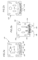
- FIGS.2a-2c illustrate three exemplary plates 130,150 and 170 composing in combination a portion of a meltblowing die assembly comprising a plurality of substantially parallel plates defining a plurality of fluid dispensing orifices arranged partially across a width extending from a right side of the die assembly to a left side thereof.
- the three plates of FIGS. 2a-2c are, more particularly, useable to replace the three plates illustrated in FIGS. 2d-2f of EP-A- (application No. 98302718.6) thereby forming a meltblowing die assembly having a partial fluid dispensing pattern illustrated generally by the die assembly 110 in FIG. 1.
- the plates of FIGS. 2a-2c may also be configured to form meltblowing die assemblies having one of the partial fluid dispensing patterns illustrated generally by the die assemblies 112, 114 and 116 in FIG. 1 and disclosed more particularly hereinabove.
- the exemplary plate of FIG. 2b includes a plurality of fluid dispensing orifices 12 disposed across a dispensing surface portion 152 between right and left sides 154 and 156 thereof. A remaining dispensing surface portion 158 is void of fluid dispensing orifices 12, whereby the corresponding die assembly incorporating the plate 150 produces a partial fluid dispensing pattern of the form illustrated generally by the die assembly 110 of FIG. 1.
- the plate 130 includes a corresponding plurality of fluid supply conduit portions 132, which supply fluid from a common fluid cavity 134 of the plate 130, in communication with a corresponding one of the plurality of fluid dispensing orifices 12 of the plate 150 when the plates 130 and 150 are matably coupled as disclosed more fully in EP-A- (application No.
- the plates 130 and 150 may of course be configured to produce any one of the partial fluid dispensing patterns illustrated generally in FIG. 1 and disclosed more particularly hereinabove.
- the plate 150 may also include fluid dispensing orifices having greater or lesser density, depending on application requirements.
- FIG. 2b illustrates each of the plurality of fluid dispensing orifices 12 flanked by an air dispensing orifice 151 disposed on opposing sides of the corresponding fluid dispensing orifice 12.
- the plate 170 includes a corresponding plurality of air supply conduit portions 172, which supply air from a common air cavity 174 of the plate 170, in communication with a corresponding one of the plurality of air dispensing orifices 151 of the plate 150 when the plates 170 and 150 are matably coupled as disclosed more fully in EP-A- (application No. 98302718.6) .
- the spacing and relative angle between the fluid and air orifices affects oscillation parameters of fluid dispensed therefrom including the frequency and amplitude thereof as discussed more fully in EP-A-0835952 and in EP-A- (application No. 98302718.6).
- FIG.2b also illustrates an-alternative embodiment wherein the remaining dispensing surface portion 158 void of fluid dispensing orifice 12 includes air dispensing orifices 153.
- the air dispensing orifices 153 improve fluid flow control by reducing a tendency of fluid dispensed from the endmost fluid dispensing orifices 12 to diverge, or stray laterally, thereby providing a more well defined boundary or interface between areas fluid coverage and non-coverage on the substrate.
- the leftmost fluid dispensing orifices, and particularly the leftmost orifice has a tendency to diverge toward the left side 158 of the plate or corresponding die assembly.
- the general concept of providing one or more additional air dispensing orifices adjacent an endmost fluid dispensing orifice to provide improved control over fluid dispensed therefrom, particularly where the endmost fluid dispensing orifice defines an interface between areas of fluid coverage and non-coverage on the substrate, is applicable to any of the die assemblies disclosed herein as well as to the meltblowing die assemblies disclosed in copending EP-A-0835952 and in EP-A- (application No. 98302718.6).
- control over the boundary or interface between areas of the substrate having fluid coverage and non-coverage is improved by decreasing the amplitude of oscillation of the fluid dispensed from the fluid dispensing orifices on the die assembly approaching and defining the boundary between areas of fluid coverage and non-coverage on the substrate.
- the oscillation amplitude of fluid is increasingly decreased in the several fluid dispensing orifices toward at least one endmost fluid dispensing orifice defining the interface between areas of fluid coverage and non-coverage on the substrate, whereby the at least one endmost fluid dispensing orifice has a smallest oscillation amplitude.
- Each die assembly has at least two and possibly more fluid dispensing orifices, depending on the configuration thereof, that dispense fluid defining boundaries between areas of fluid coverage and non-coverage on the substrate.
- FIG. 2b illustrates, for example, the air dispensing orifices 151 being disposed increasingly farther away from the corresponding fluid dispensing orifices 12 toward the left side 156 of the plate 150, thereby increasingly decreasing the oscillation amplitude of fluid dispensed from the respective fluid dispensing orifices, whereby fluid dispensed from the endmost fluid dispensing orifice has the smallest oscillation amplitude, which is controllable most accurately, thereby providing a most well defined boundary.
- the oscillation amplitude may alternatively be controlled, that is increased or decreased, by varying a relative angle between the fluid and air dispensing orifices.
- the fluid supplied to the fluid dispensing orifices having fluid flows with reduced oscillation amplitudes is correspondingly reduced, since less fluid is required for smaller oscillation amplitude.
- the corresponding air dispensing orifices may be reduced similarly, since the reduced fluid flows may be controlled with reduced air flows.
Landscapes
- Coating Apparatus (AREA)
- Nozzles (AREA)
- Application Of Or Painting With Fluid Materials (AREA)
Applications Claiming Priority (2)
| Application Number | Priority Date | Filing Date | Title |
|---|---|---|---|
| US08/940,158 US5882573A (en) | 1997-09-29 | 1997-09-29 | Adhesive dispensing nozzles for producing partial spray patterns and method therefor |
| US940158 | 1997-09-29 |
Publications (4)
| Publication Number | Publication Date |
|---|---|
| EP0904849A2 true EP0904849A2 (de) | 1999-03-31 |
| EP0904849A3 EP0904849A3 (de) | 2000-01-12 |
| EP0904849B1 EP0904849B1 (de) | 2002-11-20 |
| EP0904849B2 EP0904849B2 (de) | 2007-08-29 |
Family
ID=25474345
Family Applications (1)
| Application Number | Title | Priority Date | Filing Date |
|---|---|---|---|
| EP98307447A Expired - Lifetime EP0904849B2 (de) | 1997-09-29 | 1998-09-15 | Klebstoffsdüsen zum Besprühen eines Substrats mit Klebstoff nach einem Muster |
Country Status (11)
| Country | Link |
|---|---|
| US (1) | US5882573A (de) |
| EP (1) | EP0904849B2 (de) |
| JP (1) | JP4198793B2 (de) |
| KR (1) | KR100291436B1 (de) |
| CN (1) | CN1094798C (de) |
| AU (1) | AU704225B1 (de) |
| BR (1) | BR9803592A (de) |
| CA (1) | CA2247786C (de) |
| DE (1) | DE69809521T3 (de) |
| NZ (1) | NZ331965A (de) |
| TW (1) | TW410176B (de) |
Cited By (3)
| Publication number | Priority date | Publication date | Assignee | Title |
|---|---|---|---|---|
| WO2011014480A1 (en) * | 2009-07-29 | 2011-02-03 | Illinois Tool Works Inc. | Wide pattern nozzle |
| EP3107660A4 (de) * | 2014-02-18 | 2018-02-28 | 3M Innovative Properties Company | Verfahren und vorrichtung zur herstellung von artikeln mit ungleichmässigen beschichtungen |
| US11440067B2 (en) | 2016-06-02 | 2022-09-13 | Primetals Technologies Austria GmbH | Lubricating device for applying a lubricant when rolling a rolling material |
Families Citing this family (91)
| Publication number | Priority date | Publication date | Assignee | Title |
|---|---|---|---|---|
| US6422848B1 (en) | 1997-03-19 | 2002-07-23 | Nordson Corporation | Modular meltblowing die |
| EP1083999A4 (de) | 1998-04-17 | 2004-06-02 | Nordson Corp | Verfahren und vorrichtung zum aufbringen eines kontrollierten musters aus faserförmigem material auf ein bewegendes substrat |
| US6248097B1 (en) | 1998-08-06 | 2001-06-19 | Kimberly-Clark Worldwide, Inc. | Absorbent article with more conformable elastics |
| US6652693B2 (en) | 1998-08-06 | 2003-11-25 | Kimberly-Clark Worldwide, Inc. | Process for applying adhesive in an article having a strand material |
| US6235137B1 (en) | 1998-08-06 | 2001-05-22 | Kimberly-Clark Worldwide, Inc. | Process for manufacturing an elastic article |
| JP4474620B2 (ja) * | 2000-03-14 | 2010-06-09 | ノードソン株式会社 | 糸状又は紐状物体に接着剤を塗布する装置と方法 |
| US6719846B2 (en) | 2000-03-14 | 2004-04-13 | Nordson Corporation | Device and method for applying adhesive filaments to materials such as strands or flat substrates |
| US6361634B1 (en) | 2000-04-05 | 2002-03-26 | Kimberly-Clark Worldwide, Inc. | Multiple stage coating of elastic strands with adhesive |
| US6833179B2 (en) | 2000-05-15 | 2004-12-21 | Kimberly-Clark Worldwide, Inc. | Targeted elastic laminate having zones of different basis weights |
| US6969441B2 (en) * | 2000-05-15 | 2005-11-29 | Kimberly-Clark Worldwide, Inc. | Method and apparatus for producing laminated articles |
| US6572033B1 (en) | 2000-05-15 | 2003-06-03 | Nordson Corporation | Module for dispensing controlled patterns of liquid material and a nozzle having an asymmetric liquid discharge orifice |
| US6435425B1 (en) * | 2000-05-15 | 2002-08-20 | Nordson Corporation | Module and nozzle for dispensing controlled patterns of liquid material |
| US20050106971A1 (en) * | 2000-05-15 | 2005-05-19 | Thomas Oomman P. | Elastomeric laminate with film and strands suitable for a nonwoven garment |
| US8182457B2 (en) * | 2000-05-15 | 2012-05-22 | Kimberly-Clark Worldwide, Inc. | Garment having an apparent elastic band |
| US6375099B1 (en) | 2000-06-21 | 2002-04-23 | Illinois Tool Works Inc. | Split output adhesive nozzle assembly |
| US6733831B2 (en) | 2001-10-30 | 2004-05-11 | Nordson Corporation | Method and apparatus for use in coating elongated bands |
| US6601741B2 (en) | 2001-11-28 | 2003-08-05 | Illinois Tool Works Inc. | Laminated distribution manifold plate system |
| US6939334B2 (en) | 2001-12-19 | 2005-09-06 | Kimberly-Clark Worldwide, Inc. | Three dimensional profiling of an elastic hot melt pressure sensitive adhesive to provide areas of differential tension |
| US6805965B2 (en) | 2001-12-21 | 2004-10-19 | Kimberly-Clark Worldwide, Inc. | Method for the application of hydrophobic chemicals to tissue webs |
| US6716309B2 (en) | 2001-12-21 | 2004-04-06 | Kimberly-Clark Worldwide, Inc. | Method for the application of viscous compositions to the surface of a paper web and products made therefrom |
| US6902796B2 (en) | 2001-12-28 | 2005-06-07 | Kimberly-Clark Worldwide, Inc. | Elastic strand bonded laminate |
| US6936125B2 (en) * | 2002-03-15 | 2005-08-30 | Nordson Corporation | Method of applying a continuous adhesive filament to an elastic strand with discrete bond points and articles manufactured by the method |
| US20030173024A1 (en) * | 2002-03-15 | 2003-09-18 | Nordson Corporation | Method of securing elastic strands to flat substrates and products produced by the method |
| US20050013975A1 (en) * | 2003-07-14 | 2005-01-20 | Nordson Corporation | Method of securing elastic strands to flat substrates and products produced by the method |
| WO2003086949A2 (en) * | 2002-04-12 | 2003-10-23 | Nordson Corporation | Applicator and nozzle for dispensing controlled patterns of liquid material |
| US6911232B2 (en) | 2002-04-12 | 2005-06-28 | Nordson Corporation | Module, nozzle and method for dispensing controlled patterns of liquid material |
| US7169400B2 (en) * | 2002-05-07 | 2007-01-30 | Fort James Corporation | Waterless lotion and lotion-treated substrate |
| US8012495B2 (en) * | 2002-05-07 | 2011-09-06 | Georgia-Pacific Consumer Products Lp | Lotion-treated tissue and towel |
| US7335273B2 (en) | 2002-12-26 | 2008-02-26 | Kimberly-Clark Worldwide, Inc. | Method of making strand-reinforced elastomeric composites |
| US7316840B2 (en) | 2002-07-02 | 2008-01-08 | Kimberly-Clark Worldwide, Inc. | Strand-reinforced composite material |
| US6978486B2 (en) | 2002-07-02 | 2005-12-27 | Kimberly-Clark Worldwide, Inc. | Garment including an elastomeric composite laminate |
| US7015155B2 (en) | 2002-07-02 | 2006-03-21 | Kimberly-Clark Worldwide, Inc. | Elastomeric adhesive |
| US7316842B2 (en) | 2002-07-02 | 2008-01-08 | Kimberly-Clark Worldwide, Inc. | High-viscosity elastomeric adhesive composition |
| US6977026B2 (en) * | 2002-10-16 | 2005-12-20 | Kimberly-Clark Worldwide, Inc. | Method for applying softening compositions to a tissue product |
| EP1410900A1 (de) * | 2002-10-17 | 2004-04-21 | Reifenhäuser GmbH & Co. Maschinenfabrik | Verfahren zur Herstellung einer Verbundbahn |
| US6761800B2 (en) * | 2002-10-28 | 2004-07-13 | Kimberly-Clark Worldwide, Inc. | Process for applying a liquid additive to both sides of a tissue web |
| US20040081794A1 (en) * | 2002-10-29 | 2004-04-29 | Titone David M. | Method for applying adhesive filaments to multiple strands of material and articles formed with the method |
| US7029756B2 (en) * | 2002-11-06 | 2006-04-18 | Kimberly-Clark Worldwide, Inc. | Soft tissue hydrophilic tissue products containing polysiloxane and having unique absorbent properties |
| US6964725B2 (en) * | 2002-11-06 | 2005-11-15 | Kimberly-Clark Worldwide, Inc. | Soft tissue products containing selectively treated fibers |
| US6949168B2 (en) * | 2002-11-27 | 2005-09-27 | Kimberly-Clark Worldwide, Inc. | Soft paper product including beneficial agents |
| US6878238B2 (en) * | 2002-12-19 | 2005-04-12 | Kimberly-Clark Worldwide, Inc. | Non-woven through air dryer and transfer fabrics for tissue making |
| US6875315B2 (en) * | 2002-12-19 | 2005-04-05 | Kimberly-Clark Worldwide, Inc. | Non-woven through air dryer and transfer fabrics for tissue making |
| JP4363842B2 (ja) * | 2002-12-20 | 2009-11-11 | ユニ・チャーム株式会社 | 使い捨て着用物品 |
| US7578882B2 (en) * | 2003-01-22 | 2009-08-25 | Nordson Corporation | Module, nozzle and method for dispensing controlled patterns of liquid material |
| US7396593B2 (en) * | 2003-05-19 | 2008-07-08 | Kimberly-Clark Worldwide, Inc. | Single ply tissue products surface treated with a softening agent |
| US20050015050A1 (en) * | 2003-07-15 | 2005-01-20 | Kimberly-Clark Worldwide, Inc. | Apparatus for depositing fluid material onto a substrate |
| US7141142B2 (en) * | 2003-09-26 | 2006-11-28 | Kimberly-Clark Worldwide, Inc. | Method of making paper using reformable fabrics |
| US7168932B2 (en) * | 2003-12-22 | 2007-01-30 | Kimberly-Clark Worldwide, Inc. | Apparatus for nonwoven fibrous web |
| US20050137549A1 (en) * | 2003-12-22 | 2005-06-23 | Kimberly-Clark Worldwide, Inc. | Use of swirl-like adhesive patterns in the formation of absorbent articles |
| US6972104B2 (en) * | 2003-12-23 | 2005-12-06 | Kimberly-Clark Worldwide, Inc. | Meltblown die having a reduced size |
| US20050142339A1 (en) * | 2003-12-30 | 2005-06-30 | Price Cindy L. | Reinforced elastic laminate |
| US7601657B2 (en) | 2003-12-31 | 2009-10-13 | Kimberly-Clark Worldwide, Inc. | Single sided stretch bonded laminates, and methods of making same |
| US7228809B2 (en) * | 2004-04-15 | 2007-06-12 | Cupid Foundations, Inc. | Undergarments having finished edges and methods therefor |
| US7316552B2 (en) * | 2004-12-23 | 2008-01-08 | Kimberly-Clark Worldwide, Inc. | Low turbulence die assembly for meltblowing apparatus |
| US7465367B2 (en) * | 2005-01-07 | 2008-12-16 | Innovative Elastics Limited | Process for forming a laminate |
| US20060258249A1 (en) * | 2005-05-11 | 2006-11-16 | Fairbanks Jason S | Elastic laminates and process for producing same |
| CN100493735C (zh) * | 2006-01-17 | 2009-06-03 | 欣兴电子股份有限公司 | 涂布工艺 |
| US8388992B2 (en) | 2006-03-28 | 2013-03-05 | Georgia-Pacific Consumer Products Lp | Anti-microbial hand towel with time-delay chromatic transfer indicator and absorbency rate delay |
| US20080008865A1 (en) * | 2006-06-23 | 2008-01-10 | Georgia-Pacific Consumer Products Lp | Antimicrobial hand towel for touchless automatic dispensers |
| EA016491B1 (ru) * | 2006-12-07 | 2012-05-30 | Юни-Чарм Корпорейшн | Поглощающее изделие |
| US7951264B2 (en) | 2007-01-19 | 2011-05-31 | Georgia-Pacific Consumer Products Lp | Absorbent cellulosic products with regenerated cellulose formed in-situ |
| US20090255628A1 (en) * | 2008-04-09 | 2009-10-15 | Miller William J | Micro-article and method of making |
| US8074902B2 (en) * | 2008-04-14 | 2011-12-13 | Nordson Corporation | Nozzle and method for dispensing random pattern of adhesive filaments |
| CA2735867C (en) | 2008-09-16 | 2017-12-05 | Dixie Consumer Products Llc | Food wrap basesheet with regenerated cellulose microfiber |
| US8551562B2 (en) | 2009-07-17 | 2013-10-08 | Illnois Tool Works Inc. | Method for metering hot melt adhesives with variable adhesive volumes |
| US8445061B2 (en) * | 2009-07-17 | 2013-05-21 | Illinois Tool Works Inc. | Metering system for hot melt adhesives with variable adhesive volumes |
| CN102947011B (zh) * | 2010-06-15 | 2015-01-28 | 3M创新有限公司 | 带有多个分配针的分配歧管 |
| CN102673090B (zh) * | 2011-03-18 | 2015-01-14 | 宸鸿科技(厦门)有限公司 | 多层板贴合装置及其方法 |
| US9827711B2 (en) | 2011-04-21 | 2017-11-28 | Pregis Innovative Packaging Llc | Edge attached film-foam sheet |
| US9272799B2 (en) | 2011-10-04 | 2016-03-01 | Signode Industrial Group Llc | Sealing tool for strap |
| US9550919B2 (en) * | 2012-01-17 | 2017-01-24 | Illinois Tool Works Inc. | Anti-blocking adhesive-coated substrate, and a method for making the same |
| US8652672B2 (en) | 2012-03-15 | 2014-02-18 | Aquion Energy, Inc. | Large format electrochemical energy storage device housing and module |
| US9682392B2 (en) | 2012-04-11 | 2017-06-20 | Nordson Corporation | Method for applying varying amounts or types of adhesive on an elastic strand |
| US9480996B2 (en) | 2012-09-18 | 2016-11-01 | Ilinois Tool Works Inc. | Fluid dispensing system with nozzle heater |
| US9283579B2 (en) | 2013-03-12 | 2016-03-15 | Illinois Tool Works Inc. | Variable volume hot melt adhesive dispensing nozzle or die assembly with choke suppression |
| US10704254B2 (en) | 2014-02-18 | 2020-07-07 | 3M Innovative Properties Company | Easy to apply air and water barrier articles |
| US10526729B2 (en) | 2014-02-24 | 2020-01-07 | Nanofiber, Inc. | Melt blowing die, apparatus and method |
| US11338311B2 (en) | 2014-04-01 | 2022-05-24 | Illinois Tool Works Inc. | Fluid application device having a nozzle with individually metered orifice or orifices |
| WO2015164856A2 (en) | 2014-04-25 | 2015-10-29 | Firestone Building Products Co., LLC | Construction materials including a non-woven layer of pressure-sensitive adhesive |
| US9849480B2 (en) | 2014-11-26 | 2017-12-26 | Illinois Tool Works Inc. | Laminated nozzle with thick plate |
| US9561654B2 (en) | 2014-11-26 | 2017-02-07 | Illinois Tool Works Inc. | Laminated nozzle with thick plate |
| US11731394B2 (en) | 2014-12-22 | 2023-08-22 | 3M Innovative Properties Company | Air and water barrier articles |
| WO2017031275A1 (en) | 2015-08-18 | 2017-02-23 | 3M Innovative Properties Company | Self-sealing articles including elastic porous layer |
| US10577137B2 (en) | 2015-12-09 | 2020-03-03 | Signode Industrial Group Llc | Electrically powered combination hand-held notch-type strapping tool |
| EP3393791A4 (de) | 2015-12-22 | 2020-01-29 | 3M Innovative Properties Company | Walze mit luft- und wasserbarriereartikel und verfahren zur verwendung davon |
| US11267595B2 (en) | 2016-11-01 | 2022-03-08 | Pregis Innovative Packaging Llc | Automated furniture bagger and material therefor |
| US11365328B2 (en) | 2017-02-23 | 2022-06-21 | 3M Innovative Properties Company | Air and water barrier article including inelastic porous layer |
| WO2019104240A1 (en) | 2017-11-22 | 2019-05-31 | Extrusion Group, LLC | Meltblown die tip assembly and method |
| US11179744B2 (en) * | 2018-11-13 | 2021-11-23 | Gaston Systems, Inc. | Segmented distribution assembly for distributing fluid to an applicator nozzle |
| US12173200B2 (en) | 2019-04-04 | 2024-12-24 | Avery Dennison Corporation | Reinforced label assembly |
| EP4010184A1 (de) | 2019-08-07 | 2022-06-15 | 3M Innovative Properties Company | Band, artikel mit band und verbundschicht sowie zugehörige verfahren |
Citations (3)
| Publication number | Priority date | Publication date | Assignee | Title |
|---|---|---|---|---|
| US5421941A (en) | 1990-10-17 | 1995-06-06 | J & M Laboratories, Inc. | Method of applying an adhesive |
| EP0835952A1 (de) | 1996-10-08 | 1998-04-15 | Illinois Tool Works Inc. | Vorrichtung und Verfahren zum Schmelzblasen |
| EP0872580A1 (de) | 1997-04-14 | 1998-10-21 | Illinois Tool Works Inc. | Verfahren und Vorrichtung zum Schmelzblasen |
Family Cites Families (107)
| Publication number | Priority date | Publication date | Assignee | Title |
|---|---|---|---|---|
| US2031387A (en) * | 1934-08-22 | 1936-02-18 | Schwarz Arthur | Nozzle |
| US2212448A (en) * | 1935-06-08 | 1940-08-20 | Owens Corning Fiberglass Corp | Method and apparatus for the production of fibers from molten glass and similar meltable materials |
| US2297726A (en) * | 1938-04-02 | 1942-10-06 | Thermo Plastics Corp | Method and apparatus for drying or the like |
| BE492010A (de) | 1948-11-05 | |||
| US2628386A (en) * | 1952-04-29 | 1953-02-17 | Modern Plastic Machinery Corp | Web extrusion die |
| US3038202A (en) * | 1959-01-28 | 1962-06-12 | Multiple Extrusions Inc | Method and apparatus for making multiple tube structures by extrusion |
| DE1132896B (de) * | 1961-01-05 | 1962-07-12 | Bayer Ag | Verfahren zur Herstellung von koernigen oder zylinderfoermigen Granulaten |
| US3178770A (en) * | 1962-01-19 | 1965-04-20 | Du Pont | Variable orifice extruder die |
| NL125332C (de) * | 1962-06-25 | |||
| US3192563A (en) * | 1962-06-25 | 1965-07-06 | Monsanto Co | Laminated spinneret |
| US3176345A (en) * | 1962-06-25 | 1965-04-06 | Monsanto Co | Spinnerette |
| US3204290A (en) * | 1962-12-27 | 1965-09-07 | Monsanto Co | Laminated spinneret |
| US3501805A (en) * | 1963-01-03 | 1970-03-24 | American Cyanamid Co | Apparatus for forming multicomponent fibers |
| US3253301A (en) * | 1963-01-14 | 1966-05-31 | Monsanto Co | Non-circular spinneret orifices |
| DE1584324A1 (de) * | 1965-04-15 | 1969-12-18 | Schneider & Co | Vorrichtung zur Herstellung keramischer Koerper |
| US3334792A (en) * | 1966-05-19 | 1967-08-08 | Herculite Protective Fab | Adhesive applicator |
| DE1969216U (de) * | 1966-10-24 | 1967-09-28 | Du Pont | Spinnpackung. |
| NL6801610A (de) * | 1967-02-07 | 1968-08-08 | ||
| US3978185A (en) * | 1968-12-23 | 1976-08-31 | Exxon Research And Engineering Company | Melt blowing process |
| US3849241A (en) * | 1968-12-23 | 1974-11-19 | Exxon Research Engineering Co | Non-woven mats by melt blowing |
| US3613170A (en) * | 1969-05-27 | 1971-10-19 | American Cyanamid Co | Spinning apparatus for sheath-core bicomponent fibers |
| US3704198A (en) * | 1969-10-09 | 1972-11-28 | Exxon Research Engineering Co | Nonwoven polypropylene mats of increased strip tensile strength |
| US3650866A (en) * | 1969-10-09 | 1972-03-21 | Exxon Research Engineering Co | Increasing strip tensile strength of melt blown nonwoven polypropylene mats of high tear resistance |
| US3755527A (en) * | 1969-10-09 | 1973-08-28 | Exxon Research Engineering Co | Process for producing melt blown nonwoven synthetic polymer mat having high tear resistance |
| US3947537A (en) * | 1971-07-16 | 1976-03-30 | Exxon Research & Engineering Co. | Battery separator manufacturing process |
| BE787033A (de) * | 1971-08-06 | 1973-02-01 | Solvay | |
| BE795841A (fr) | 1972-02-25 | 1973-08-23 | Montedison Spa | Procede de preparation de fibres a partir de matieres polymeres, convenant a la preparation de pulpe de papier |
| US3825379A (en) * | 1972-04-10 | 1974-07-23 | Exxon Research Engineering Co | Melt-blowing die using capillary tubes |
| US3861850A (en) * | 1972-09-05 | 1975-01-21 | Marvin E Wallis | Film forming head |
| US3920362A (en) * | 1972-10-27 | 1975-11-18 | Jeffers Albert L | Filament forming apparatus with sweep fluid channel surrounding spinning needle |
| US4052183A (en) * | 1973-04-24 | 1977-10-04 | Saint-Gobain Industries | Method and apparatus for suppression of pollution in toration of glass fibers |
| US4015964A (en) * | 1973-03-30 | 1977-04-05 | Saint-Gobain Industries | Method and apparatus for making fibers from thermoplastic materials |
| FR2223318B1 (de) * | 1973-03-30 | 1978-03-03 | Saint Gobain | |
| US4015963A (en) * | 1973-03-30 | 1977-04-05 | Saint-Gobain Industries | Method and apparatus for forming fibers by toration |
| US3888610A (en) * | 1973-08-24 | 1975-06-10 | Rothmans Of Pall Mall | Formation of polymeric fibres |
| US4100324A (en) * | 1974-03-26 | 1978-07-11 | Kimberly-Clark Corporation | Nonwoven fabric and method of producing same |
| US3970417A (en) * | 1974-04-24 | 1976-07-20 | Beloit Corporation | Twin triple chambered gas distribution system for melt blown microfiber production |
| US3942723A (en) * | 1974-04-24 | 1976-03-09 | Beloit Corporation | Twin chambered gas distribution system for melt blown microfiber production |
| US3923444A (en) * | 1974-05-03 | 1975-12-02 | Ford Motor Co | Extrusion die |
| DD115206A5 (de) * | 1974-07-13 | 1975-09-12 | Monforts Fa A | Fluidik-oszillator |
| US4052002A (en) * | 1974-09-30 | 1977-10-04 | Bowles Fluidics Corporation | Controlled fluid dispersal techniques |
| US3981650A (en) * | 1975-01-16 | 1976-09-21 | Beloit Corporation | Melt blowing intermixed filaments of two different polymers |
| NL7507443A (nl) * | 1975-06-23 | 1976-12-27 | Akzo Nv | Smeltspingarnituur. |
| US4185981A (en) * | 1975-08-20 | 1980-01-29 | Nippon Sheet Glass Co.,Ltd. | Method for producing fibers from heat-softening materials |
| DE2614596C3 (de) * | 1976-04-05 | 1980-03-13 | Vereinigte Glaswerke Gmbh, 5100 Aachen | Abstreichgießkopf zum Aufbringen gießfähiger Kunststoffschichten auf plane Unterlagen |
| US4151955A (en) * | 1977-10-25 | 1979-05-01 | Bowles Fluidics Corporation | Oscillating spray device |
| US5035361A (en) * | 1977-10-25 | 1991-07-30 | Bowles Fluidics Corporation | Fluid dispersal device and method |
| USRE33448E (en) * | 1977-12-09 | 1990-11-20 | Fluidic oscillator and spray-forming output chamber | |
| USRE33605E (en) * | 1977-12-09 | 1991-06-04 | Fluidic oscillator and spray-forming output chamber | |
| US4277436A (en) * | 1978-04-26 | 1981-07-07 | Owens-Corning Fiberglas Corporation | Method for forming filaments |
| US4231519A (en) * | 1979-03-09 | 1980-11-04 | Peter Bauer | Fluidic oscillator with resonant inertance and dynamic compliance circuit |
| US4300876A (en) * | 1979-12-12 | 1981-11-17 | Owens-Corning Fiberglas Corporation | Apparatus for fluidically attenuating filaments |
| US4359445A (en) * | 1980-01-21 | 1982-11-16 | Owens-Corning Fiberglas Corporation | Method for producing a lofted mat |
| US4380570A (en) * | 1980-04-08 | 1983-04-19 | Schwarz Eckhard C A | Apparatus and process for melt-blowing a fiberforming thermoplastic polymer and product produced thereby |
| US4340563A (en) * | 1980-05-05 | 1982-07-20 | Kimberly-Clark Corporation | Method for forming nonwoven webs |
| DE3148477C2 (de) * | 1981-12-08 | 1983-12-22 | Maschinenbau Oppenweiler Binder GmbH & Co, 7155 Oppenweiler | Leimauftragskopf |
| US4457685A (en) * | 1982-01-04 | 1984-07-03 | Mobil Oil Corporation | Extrusion die for shaped extrudate |
| US4526733A (en) * | 1982-11-17 | 1985-07-02 | Kimberly-Clark Corporation | Meltblown die and method |
| DE3475083D1 (en) * | 1983-03-23 | 1988-12-15 | Barmag Barmer Maschf | Spinning head for melt-spinning filaments |
| US4596364A (en) * | 1984-01-11 | 1986-06-24 | Peter Bauer | High-flow oscillator |
| US4818464A (en) * | 1984-08-30 | 1989-04-04 | Kimberly-Clark Corporation | Extrusion process using a central air jet |
| DE3506393A1 (de) * | 1985-02-23 | 1986-08-28 | Windmöller & Hölscher, 4540 Lengerich | Leimauftragsvorrichtung |
| DE3506924A1 (de) * | 1985-02-27 | 1986-09-04 | Reifenhäuser GmbH & Co Maschinenfabrik, 5210 Troisdorf | Einrichtung fuer das spinnen von monofilfaeden aus thermoplastischem kunststoff |
| FR2579516B1 (fr) * | 1985-04-01 | 1987-06-12 | Solvay | Bloc d'alimentation pour filiere plate de coextrusion |
| US4694992A (en) * | 1985-06-24 | 1987-09-22 | Bowles Fluidics Corporation | Novel inertance loop construction for air sweep fluidic oscillator |
| EP0252909B1 (de) * | 1986-01-10 | 1990-11-07 | Accurate Products Company | Schmelzblasdüse und luftverteilereinrichtung |
| US4874451A (en) * | 1986-03-20 | 1989-10-17 | Nordson Corporation | Method of forming a disposable diaper with continuous/intermittent rows of adhesive |
| US4818463A (en) * | 1986-04-26 | 1989-04-04 | Buehning Peter G | Process for preparing non-woven webs |
| DE3784619T2 (de) * | 1986-10-21 | 1993-06-17 | Mitsui Petrochemical Ind | Extrusionsduese zum schmelzblasen. |
| US4747986A (en) * | 1986-12-24 | 1988-05-31 | Allied-Signal Inc. | Die and method for forming honeycomb structures |
| US4746283A (en) * | 1987-04-01 | 1988-05-24 | Hobson Gerald R | Head tooling parison adapter plates |
| US4785996A (en) * | 1987-04-23 | 1988-11-22 | Nordson Corporation | Adhesive spray gun and nozzle attachment |
| USRE33481E (en) * | 1987-04-23 | 1990-12-11 | Nordson Corporation | Adhesive spray gun and nozzle attachment |
| US4955547A (en) * | 1987-09-02 | 1990-09-11 | Spectra Technologies, Inc. | Fluidic oscillating nozzle |
| US4905909A (en) * | 1987-09-02 | 1990-03-06 | Spectra Technologies, Inc. | Fluidic oscillating nozzle |
| US4923706A (en) * | 1988-01-14 | 1990-05-08 | Thomas J. Lipton, Inc. | Process of and apparatus for shaping extrudable material |
| US4983109A (en) * | 1988-01-14 | 1991-01-08 | Nordson Corporation | Spray head attachment for metering gear head |
| US4812276A (en) * | 1988-04-29 | 1989-03-14 | Allied-Signal Inc. | Stepwise formation of channel walls in honeycomb structures |
| US4949668A (en) * | 1988-06-16 | 1990-08-21 | Kimberly-Clark Corporation | Apparatus for sprayed adhesive diaper construction |
| US5069853A (en) * | 1988-06-17 | 1991-12-03 | Gencorp Inc. | Method of configuring extrudate flowing from an extruder die assembly |
| US5067885A (en) * | 1988-06-17 | 1991-11-26 | Gencorp Inc. | Rapid change die assembly |
| US5114752A (en) * | 1988-12-12 | 1992-05-19 | Nordson Corporation | Method for gas-aided dispensing of liquid materials |
| US5017116A (en) * | 1988-12-29 | 1991-05-21 | Monsanto Company | Spinning pack for wet spinning bicomponent filaments |
| DE3927254A1 (de) * | 1989-08-18 | 1991-02-21 | Reifenhaeuser Masch | Verfahren und spinnduesenaggregat fuer die herstellung von kunststoff-faeden und/oder kunststoff-fasern im zuge der herstellung von einem spinnvlies aus thermoplastischem kunststoff |
| US5013232A (en) * | 1989-08-24 | 1991-05-07 | General Motors Corporation | Extrusion die construction |
| US5066435A (en) * | 1989-09-16 | 1991-11-19 | Rohm Gmbh Chemische Fabrik | Process and system for producing multi-layer extrudate |
| DE4040242A1 (de) * | 1990-12-15 | 1992-06-17 | Peter Roger Dipl Ing Nyssen | Verfahren und vorrichtung zur herstellung von feinstfasern aus thermoplastischen polymeren |
| JP2602460B2 (ja) * | 1991-01-17 | 1997-04-23 | 三菱化学株式会社 | 紡糸ノズル及び該紡糸ノズルを用いた金属化合物の繊維前駆体の製造法ならびに無機酸化物繊維の製造法 |
| US5094792A (en) * | 1991-02-27 | 1992-03-10 | General Motors Corporation | Adjustable extrusion coating die |
| US5129585A (en) * | 1991-05-21 | 1992-07-14 | Peter Bauer | Spray-forming output device for fluidic oscillators |
| US5207970A (en) * | 1991-09-30 | 1993-05-04 | Minnesota Mining And Manufacturing Company | Method of forming a web of melt blown layered fibers |
| US5382312A (en) | 1992-04-08 | 1995-01-17 | Nordson Corporation | Dual format adhesive apparatus for intermittently disrupting parallel, straight lines of adhesive to form a band |
| US5165940A (en) * | 1992-04-23 | 1992-11-24 | E. I. Du Pont De Nemours And Company | Spinneret |
| DE69317706T2 (de) * | 1992-07-08 | 1998-07-30 | Nordson Corp | Apparat und Verfahren zum Auftrag von diskontinuierlichen Beschichtungen |
| DE69314343T2 (de) * | 1992-07-08 | 1998-03-26 | Nordson Corp | Vorrichtung und verfahren zum aufbringen von schaumbeschichtungen |
| CA2098784A1 (en) * | 1992-07-08 | 1994-01-09 | Bentley Boger | Apparatus and methods for applying conformal coatings to electronic circuit boards |
| US5421921A (en) * | 1992-07-08 | 1995-06-06 | Nordson Corporation | Segmented slot die for air spray of fibers |
| US5354378A (en) * | 1992-07-08 | 1994-10-11 | Nordson Corporation | Slot nozzle apparatus for applying coatings to bottles |
| US5418009A (en) * | 1992-07-08 | 1995-05-23 | Nordson Corporation | Apparatus and methods for intermittently applying discrete adhesive coatings |
| US5305955A (en) * | 1993-03-25 | 1994-04-26 | Illinois Tool Works Inc. | Nozzle bar with adjustable pattern |
| DE4332345C2 (de) | 1993-09-23 | 1995-09-14 | Reifenhaeuser Masch | Verfahren und Vliesblasanlage zur Herstellung von einem Spinnvlies mit hoher Filamentgeschwindigkeit |
| US5478224A (en) | 1994-02-04 | 1995-12-26 | Illinois Tool Works Inc. | Apparatus for depositing a material on a substrate and an applicator head therefor |
| US5458291A (en) | 1994-03-16 | 1995-10-17 | Nordson Corporation | Fluid applicator with a noncontacting die set |
| US5679379A (en) | 1995-01-09 | 1997-10-21 | Fabbricante; Anthony S. | Disposable extrusion apparatus with pressure balancing modular die units for the production of nonwoven webs |
| US5618347A (en) | 1995-04-14 | 1997-04-08 | Kimberly-Clark Corporation | Apparatus for spraying adhesive |
| US5618566A (en) | 1995-04-26 | 1997-04-08 | Exxon Chemical Patents, Inc. | Modular meltblowing die |
| US5620139A (en) | 1995-07-18 | 1997-04-15 | Nordson Corporation | Nozzle adapter with recirculation valve |
-
1997
- 1997-09-29 US US08/940,158 patent/US5882573A/en not_active Expired - Lifetime
-
1998
- 1998-08-31 TW TW087114431A patent/TW410176B/zh not_active IP Right Cessation
- 1998-09-15 DE DE69809521T patent/DE69809521T3/de not_active Expired - Lifetime
- 1998-09-15 EP EP98307447A patent/EP0904849B2/de not_active Expired - Lifetime
- 1998-09-18 CA CA002247786A patent/CA2247786C/en not_active Expired - Fee Related
- 1998-09-18 NZ NZ331965A patent/NZ331965A/xx not_active IP Right Cessation
- 1998-09-18 KR KR1019980038735A patent/KR100291436B1/ko not_active Expired - Lifetime
- 1998-09-22 BR BR9803592-4A patent/BR9803592A/pt active IP Right Grant
- 1998-09-25 AU AU87055/98A patent/AU704225B1/en not_active Ceased
- 1998-09-29 CN CN98120066A patent/CN1094798C/zh not_active Expired - Lifetime
- 1998-09-29 JP JP27561198A patent/JP4198793B2/ja not_active Expired - Lifetime
Patent Citations (3)
| Publication number | Priority date | Publication date | Assignee | Title |
|---|---|---|---|---|
| US5421941A (en) | 1990-10-17 | 1995-06-06 | J & M Laboratories, Inc. | Method of applying an adhesive |
| EP0835952A1 (de) | 1996-10-08 | 1998-04-15 | Illinois Tool Works Inc. | Vorrichtung und Verfahren zum Schmelzblasen |
| EP0872580A1 (de) | 1997-04-14 | 1998-10-21 | Illinois Tool Works Inc. | Verfahren und Vorrichtung zum Schmelzblasen |
Cited By (7)
| Publication number | Priority date | Publication date | Assignee | Title |
|---|---|---|---|---|
| WO2011014480A1 (en) * | 2009-07-29 | 2011-02-03 | Illinois Tool Works Inc. | Wide pattern nozzle |
| CN102470388A (zh) * | 2009-07-29 | 2012-05-23 | 伊利诺斯工具制品有限公司 | 宽图案喷嘴 |
| CN102470388B (zh) * | 2009-07-29 | 2016-02-17 | 伊利诺斯工具制品有限公司 | 宽图案喷嘴 |
| US9321060B2 (en) | 2009-07-29 | 2016-04-26 | Illinois Tool Works Inc. | Wide pattern nozzle |
| US10213805B2 (en) | 2009-07-29 | 2019-02-26 | Illinois Tool Works Inc. | Wide pattern nozzle |
| EP3107660A4 (de) * | 2014-02-18 | 2018-02-28 | 3M Innovative Properties Company | Verfahren und vorrichtung zur herstellung von artikeln mit ungleichmässigen beschichtungen |
| US11440067B2 (en) | 2016-06-02 | 2022-09-13 | Primetals Technologies Austria GmbH | Lubricating device for applying a lubricant when rolling a rolling material |
Also Published As
| Publication number | Publication date |
|---|---|
| NZ331965A (en) | 1999-06-29 |
| DE69809521T2 (de) | 2003-07-10 |
| US5882573A (en) | 1999-03-16 |
| EP0904849B1 (de) | 2002-11-20 |
| JPH11156268A (ja) | 1999-06-15 |
| EP0904849B2 (de) | 2007-08-29 |
| TW410176B (en) | 2000-11-01 |
| DE69809521D1 (de) | 2003-01-02 |
| KR19990029950A (ko) | 1999-04-26 |
| CN1212908A (zh) | 1999-04-07 |
| CA2247786C (en) | 2002-08-20 |
| CN1094798C (zh) | 2002-11-27 |
| JP4198793B2 (ja) | 2008-12-17 |
| EP0904849A3 (de) | 2000-01-12 |
| CA2247786A1 (en) | 1999-03-29 |
| AU704225B1 (en) | 1999-04-15 |
| DE69809521T3 (de) | 2008-02-21 |
| KR100291436B1 (ko) | 2001-10-19 |
| BR9803592A (pt) | 1999-09-28 |
Similar Documents
| Publication | Publication Date | Title |
|---|---|---|
| EP0904849B1 (de) | Klebstoffsdüsen zum Besprühen eines Substrats mit Klebstoff nach einem Muster | |
| AU699826B2 (en) | Meltblowing method and apparatus | |
| EP2110184B1 (de) | Düse und Verfahren zur Ausgabe eines Zufallsmusters von Klebstofffäden | |
| US5769947A (en) | Applicator for adhesive and corresponding nozzle plate | |
| AU697804B2 (en) | Method for applying an elastic member to a moving substrate | |
| US11583887B2 (en) | Slot nozzle for adhesive applicators | |
| EP0324170A2 (de) | Spritzdüse für Dosierkopf mit einer Zahnradpumpe | |
| JP6877877B2 (ja) | ノズル | |
| US20050015050A1 (en) | Apparatus for depositing fluid material onto a substrate | |
| US20250289021A1 (en) | Nozzle arrangement for applying fluids, system having such a nozzle arrangement, and method for applying fluids | |
| JP2003285004A (ja) | 弾性ストランドを平坦基体に固着する方法およびその方法により製造される製品 | |
| MXPA98007880A (en) | Distributing adhesive nozzles to produce partial spray patterns and method of mis | |
| US20180369024A1 (en) | Nozzle assembly used to manufacture absorbent articles | |
| EP0750948A1 (de) | Verfahren und Vorrichtung zum Auftragen von Klebemitteln | |
| CN119136918A (zh) | 全覆盖/细线喷涂应用 | |
| JP5295492B2 (ja) | 粘性流体材料の楕円状螺旋パターンを形成するノズル、粘性流体材料を基材に塗布する方法、及び製品 | |
| JP7391838B2 (ja) | 流体振動構造を有するモジュール式接触ノズルを備える流体塗布装置 | |
| WO2003043554A1 (en) | Apparatus and method to produce topography and materials having topography |
Legal Events
| Date | Code | Title | Description |
|---|---|---|---|
| PUAI | Public reference made under article 153(3) epc to a published international application that has entered the european phase |
Free format text: ORIGINAL CODE: 0009012 |
|
| AK | Designated contracting states |
Kind code of ref document: A2 Designated state(s): CH DE FR GB IT LI NL SE |
|
| AX | Request for extension of the european patent |
Free format text: AL;LT;LV;MK;RO;SI |
|
| PUAL | Search report despatched |
Free format text: ORIGINAL CODE: 0009013 |
|
| AK | Designated contracting states |
Kind code of ref document: A3 Designated state(s): AT BE CH CY DE DK ES FI FR GB GR IE IT LI LU MC NL PT SE |
|
| AX | Request for extension of the european patent |
Free format text: AL;LT;LV;MK;RO;SI |
|
| 17P | Request for examination filed |
Effective date: 20000630 |
|
| AKX | Designation fees paid |
Free format text: CH DE FR GB IT LI NL SE |
|
| 17Q | First examination report despatched |
Effective date: 20010808 |
|
| GRAG | Despatch of communication of intention to grant |
Free format text: ORIGINAL CODE: EPIDOS AGRA |
|
| RTI1 | Title (correction) |
Free format text: ADHESIVE DISPENSING NOZZLES FOR PRODUCING PARTIAL SPRAY PATTERNS |
|
| GRAG | Despatch of communication of intention to grant |
Free format text: ORIGINAL CODE: EPIDOS AGRA |
|
| GRAH | Despatch of communication of intention to grant a patent |
Free format text: ORIGINAL CODE: EPIDOS IGRA |
|
| GRAH | Despatch of communication of intention to grant a patent |
Free format text: ORIGINAL CODE: EPIDOS IGRA |
|
| GRAA | (expected) grant |
Free format text: ORIGINAL CODE: 0009210 |
|
| AK | Designated contracting states |
Kind code of ref document: B1 Designated state(s): CH DE FR GB IT LI NL SE |
|
| PG25 | Lapsed in a contracting state [announced via postgrant information from national office to epo] |
Ref country code: NL Free format text: LAPSE BECAUSE OF FAILURE TO SUBMIT A TRANSLATION OF THE DESCRIPTION OR TO PAY THE FEE WITHIN THE PRESCRIBED TIME-LIMIT Effective date: 20021120 Ref country code: LI Free format text: LAPSE BECAUSE OF FAILURE TO SUBMIT A TRANSLATION OF THE DESCRIPTION OR TO PAY THE FEE WITHIN THE PRESCRIBED TIME-LIMIT Effective date: 20021120 Ref country code: CH Free format text: LAPSE BECAUSE OF FAILURE TO SUBMIT A TRANSLATION OF THE DESCRIPTION OR TO PAY THE FEE WITHIN THE PRESCRIBED TIME-LIMIT Effective date: 20021120 |
|
| REG | Reference to a national code |
Ref country code: GB Ref legal event code: FG4D |
|
| REG | Reference to a national code |
Ref country code: CH Ref legal event code: EP |
|
| REF | Corresponds to: |
Ref document number: 69809521 Country of ref document: DE Date of ref document: 20030102 |
|
| ET | Fr: translation filed | ||
| NLV1 | Nl: lapsed or annulled due to failure to fulfill the requirements of art. 29p and 29m of the patents act | ||
| REG | Reference to a national code |
Ref country code: CH Ref legal event code: PL |
|
| PLBQ | Unpublished change to opponent data |
Free format text: ORIGINAL CODE: EPIDOS OPPO |
|
| PLBI | Opposition filed |
Free format text: ORIGINAL CODE: 0009260 |
|
| PLAX | Notice of opposition and request to file observation + time limit sent |
Free format text: ORIGINAL CODE: EPIDOSNOBS2 |
|
| 26 | Opposition filed |
Opponent name: KIMBERLY-CLARK CORPORATION Effective date: 20030820 |
|
| PLBB | Reply of patent proprietor to notice(s) of opposition received |
Free format text: ORIGINAL CODE: EPIDOSNOBS3 |
|
| PLAY | Examination report in opposition despatched + time limit |
Free format text: ORIGINAL CODE: EPIDOSNORE2 |
|
| PLBC | Reply to examination report in opposition received |
Free format text: ORIGINAL CODE: EPIDOSNORE3 |
|
| PLAY | Examination report in opposition despatched + time limit |
Free format text: ORIGINAL CODE: EPIDOSNORE2 |
|
| PLBC | Reply to examination report in opposition received |
Free format text: ORIGINAL CODE: EPIDOSNORE3 |
|
| PUAH | Patent maintained in amended form |
Free format text: ORIGINAL CODE: 0009272 |
|
| STAA | Information on the status of an ep patent application or granted ep patent |
Free format text: STATUS: PATENT MAINTAINED AS AMENDED |
|
| 27A | Patent maintained in amended form |
Effective date: 20070829 |
|
| AK | Designated contracting states |
Kind code of ref document: B2 Designated state(s): CH DE FR GB IT LI NL SE |
|
| REG | Reference to a national code |
Ref country code: SE Ref legal event code: RPEO |
|
| ET3 | Fr: translation filed ** decision concerning opposition | ||
| PLAB | Opposition data, opponent's data or that of the opponent's representative modified |
Free format text: ORIGINAL CODE: 0009299OPPO |
|
| REG | Reference to a national code |
Ref country code: FR Ref legal event code: PLFP Year of fee payment: 19 |
|
| PGFP | Annual fee paid to national office [announced via postgrant information from national office to epo] |
Ref country code: GB Payment date: 20160927 Year of fee payment: 19 |
|
| PGFP | Annual fee paid to national office [announced via postgrant information from national office to epo] |
Ref country code: SE Payment date: 20160928 Year of fee payment: 19 Ref country code: FR Payment date: 20160926 Year of fee payment: 19 |
|
| PGFP | Annual fee paid to national office [announced via postgrant information from national office to epo] |
Ref country code: IT Payment date: 20170925 Year of fee payment: 20 |
|
| PGFP | Annual fee paid to national office [announced via postgrant information from national office to epo] |
Ref country code: DE Payment date: 20170927 Year of fee payment: 20 |
|
| REG | Reference to a national code |
Ref country code: SE Ref legal event code: EUG |
|
| GBPC | Gb: european patent ceased through non-payment of renewal fee |
Effective date: 20170915 |
|
| REG | Reference to a national code |
Ref country code: FR Ref legal event code: ST Effective date: 20180531 |
|
| PG25 | Lapsed in a contracting state [announced via postgrant information from national office to epo] |
Ref country code: GB Free format text: LAPSE BECAUSE OF NON-PAYMENT OF DUE FEES Effective date: 20170915 |
|
| PG25 | Lapsed in a contracting state [announced via postgrant information from national office to epo] |
Ref country code: FR Free format text: LAPSE BECAUSE OF NON-PAYMENT OF DUE FEES Effective date: 20171002 |
|
| REG | Reference to a national code |
Ref country code: DE Ref legal event code: R071 Ref document number: 69809521 Country of ref document: DE |
|
| PG25 | Lapsed in a contracting state [announced via postgrant information from national office to epo] |
Ref country code: SE Free format text: LAPSE BECAUSE OF NON-PAYMENT OF DUE FEES Effective date: 20170916 |