EP0903958A2 - Verfahren und Vorrichtungen zum Aufbau von Punkt-zu-Mehrpunkt-Verbindungen und Mehrpunkt-zu-Punkt-Verbindungen - Google Patents
Verfahren und Vorrichtungen zum Aufbau von Punkt-zu-Mehrpunkt-Verbindungen und Mehrpunkt-zu-Punkt-Verbindungen Download PDFInfo
- Publication number
- EP0903958A2 EP0903958A2 EP98440174A EP98440174A EP0903958A2 EP 0903958 A2 EP0903958 A2 EP 0903958A2 EP 98440174 A EP98440174 A EP 98440174A EP 98440174 A EP98440174 A EP 98440174A EP 0903958 A2 EP0903958 A2 EP 0903958A2
- Authority
- EP
- European Patent Office
- Prior art keywords
- connections
- switching
- multipoint
- point
- inputs
- Prior art date
- Legal status (The legal status is an assumption and is not a legal conclusion. Google has not performed a legal analysis and makes no representation as to the accuracy of the status listed.)
- Withdrawn
Links
Images

Classifications
-
- H—ELECTRICITY
- H04—ELECTRIC COMMUNICATION TECHNIQUE
- H04Q—SELECTING
- H04Q11/00—Selecting arrangements for multiplex systems
- H04Q11/04—Selecting arrangements for multiplex systems for time-division multiplexing
- H04Q11/0428—Integrated services digital network, i.e. systems for transmission of different types of digitised signals, e.g. speech, data, telecentral, television signals
- H04Q11/0478—Provisions for broadband connections
-
- H—ELECTRICITY
- H04—ELECTRIC COMMUNICATION TECHNIQUE
- H04J—MULTIPLEX COMMUNICATION
- H04J2203/00—Aspects of optical multiplex systems other than those covered by H04J14/05 and H04J14/07
- H04J2203/0001—Provisions for broadband connections in integrated services digital network using frames of the Optical Transport Network [OTN] or using synchronous transfer mode [STM], e.g. SONET, SDH
- H04J2203/0003—Switching fabrics, e.g. transport network, control network
- H04J2203/0019—Multicast/broadcast capabilities
-
- H—ELECTRICITY
- H04—ELECTRIC COMMUNICATION TECHNIQUE
- H04J—MULTIPLEX COMMUNICATION
- H04J2203/00—Aspects of optical multiplex systems other than those covered by H04J14/05 and H04J14/07
- H04J2203/0001—Provisions for broadband connections in integrated services digital network using frames of the Optical Transport Network [OTN] or using synchronous transfer mode [STM], e.g. SONET, SDH
- H04J2203/0057—Operations, administration and maintenance [OAM]
- H04J2203/006—Fault tolerance and recovery
Definitions
- the present invention relates to a method for establishing point-to-multipoint connections and multipoint-to-point connections in one Switching matrix according to the preamble of claim 1, a switching matrix for this according to the preamble of claim 2, a control device therefor according to the preamble of claim 3 and an exchange therefor according to the preamble of claim 4
- ITU-T Recommendation G.841 "Types and Characteristics of SDH Network Protection Architectures describes the splitting of an incoming connection line in a switching matrix into several connecting cables and the coupling of several incoming connecting cables in a further switching matrix to a common connecting cable "version April 1995 Figure 5-7 (page 51) in the field of SDH technology (S ynchrone D igital H ierarchie) known.
- one switching matrix input is connected to several switching matrix outputs by a point-to-multipoint connection and several switching matrix inputs are connected to one switching matrix output by a multiple-point-to-point connection.
- a first pair of data source and data sink indicated by arrows is connected to a second pair of data source and data sink via a first switching matrix ("matrix connection"), two redundant transmission path pairs and a second switching matrix ("matrix connection").
- the switching networks mentioned are parts of SDH network nodes, so-called "crossconnects".
- the paired arrangement of the transmission paths is required here for transmission in full duplex mode. For a transmission in half duplex mode or for a unidirectional transmission, only one channel of the transmission path pairs would be required.
- the active transmission path for data transmission pair is referred to as SNCw compound (S ub n etwork C onnection w orking), the redundant transmission path pair as SNCP compound (S ub n etwork C onnection p rotection).
- SNCw compound S ub n etwork C onnection w orking
- SNCP compound S ub n etwork C onnection p rotection
- a to be transmitted from the first data source to the second data sink Data stream is duplicated from the first switching matrix and the data stream and its duplicate in parallel on one channel of the redundant transmission paths SNCp and SNCw sent to the data sink.
- the data stream and its duplicate from the second switching matrix received the redundant transmission paths and coupled together.
- the data stream and duplicate are checked for their quality so that from this, if possible, an error-free received data stream selected and the data sink can be sent. If not both redundant transmission paths fail at the same time or have faults, can the data stream in the manner described above with high Transmission quality and transmission security from the data source to Data sink are transmitted.
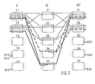
- Figure 1 shows a switching matrix in three stages of five switching modules each with currently used connections between the switching modules of the three stages.
- the Switching matrix consists of an input stage (I) with five switching modules 11, 12, 13, 14, and 15, an intermediate stage (II) with five switching modules 21, 22, 23, 24 and 25 and an output stage (III) with five switching modules 31, 32, 33, 34 and 35.
- Each of the five switching modules of the input (I) and the Output stage (III) is with each of the five switching modules of intermediate stage (II) connected via intermediate lines, not shown in the figure. Shown However, are connections that run over these intermediate lines, so that some intermediate lines become indirectly recognizable.
- the Between lines are between input stage (I) and intermediate stage (II) and between intermediate stage (II) and output stage (III).
- An intermediate line always exists between an output of a switching module of a stage and one input of a switching module of an adjacent stage.
- Such Intermediate line is e.g. between the switching modules 11 and 21 used.
- the switching modules each have five inputs and five outputs.
- An input of a switching module can be within the Switching modules in a selectable manner with at least one output of the same Switch modules are connected.
- An output of a switching module can also selectable with at least one input of the same switching module get connected.
- a switching module can have up to five independent modules Connections between one of its entrances and one of its Switch outputs at the same time.
- the switching modules 11 and 31 have one such a switching state.
- Switching modules of the switching matrix is a direct connection of the on and Exits by horizontal lines between the inputs and outputs shown. This is only intended to be a simple illustration.
- connections described at the outset are also possible the data received from the switching matrix on one of its inputs duplicated and sent in parallel to several of its outlets.
- constellations are called point-to-multipoint connections or “Multicast connections” referred to.
- Multicast connections are in the Figures made with thick, dashed lines.
- Such a “multicast connection” is e.g. switched in the switching module 24, the input side too Switching module 11 and on the output side leads to the switching modules 31 and 32.
- Another “multicast connection” leads from input A14 of the Switch module 14 via the switch module 24 to the output A33 of the Switch module 33 and to output A34 of switch module 34.
- Duplicate data streams are preferably on different Transfer trunk groups. These trunk groups then lead to incoming data streams on different switching modules of the Input stage (I) or begin for outgoing data streams different switching modules of the output stage (III).
- "Merge connections" are advantageous already in switching modules of the Intermediate stage (II) interconnected to only intermediate lines between Input (I) and intermediate (II) and not between intermediate (II) and Load output stage (III) with duplicated data streams. It is the same useful, the "multicast connections" only in the switching modules of the Intermediate stage (II) to split, because only the intermediate lines between Intermediate (II) and output stage (III) must carry duplicated data streams.
- Coupling of "merge connections” and splitting of "Multicast connections” can also be used in switching modules of other levels Switching matrix take place, especially also in switching matrixes with more levels than in the switching matrix shown in Figure 1. In any case, one is possible early coupling and splitting as late as possible is advantageous.
- FIG. 1 shows that Switch module 24 that through the lower utilization of the number of inputs compared to the number of outputs only the output to Switch module 35 remains usable. This enables the connection a between Switch module 12 and 24 only on the switch module 35 and its Outputs are continued, but not e.g. to the exits of the others Switching modules of the output stage (III).
- the part leading to intermediate (II) This "unicast connection" is indicated by a dash-dotted, thin line Figure 1 shown. A blockage occurs within the switching matrix, if the dash-dotted line in Figure 1 because of a connection request Connection a shown to an output of the switching modules 31- 34 shall be.
- the object of the invention is point-to-multipoint connections in a switching matrix of the type mentioned and multipoint-to-point connections under Taking into account the respective blocking probability.
- a symmetrical number of inputs and of Outputs of a switching module to be used for connections by a "Merge connection” a switching module with an asymmetrically higher one Load on the outputs and a switching module for a "multicast connection” is selected with an asymmetrically higher load on the inputs.
- an asymmetry parameter for each switching module led to the "merge” and “multicast connections” reversed impact proportionally.
- the asymmetry parameter could e.g. are a number, each the difference between the two Number of inputs and outputs used for "merge connections” increased or is reduced for "multicast connections”.
- a symmetrical one A switching module is loaded when it is loaded.
- the asymmetry parameter is kept as small as possible.
- Other approaches to forming the asymmetry parameter are possible, but are not explained in more detail here.
- the number too occupying inputs and outputs and already occupied inputs and outputs of a Switching modules are represented by a two-dimensional vector, whose difference vector consists of two elements that are as large as possible should.
- the switching module 24 splits the multicast connection from Switch module 11 to the switch module 31 and 32. This results in an asymmetrically higher load on the output side and from the difference one occupied input and two occupied outputs Asymmetry parameter with the value minus one.
- the switching module 25 is has an asymmetrically higher load on the input side and has one Asymmetry parameter with the value plus one, formed from the difference of two occupied inputs and one occupied output.
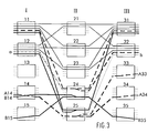
- the switching matrix in FIG. 2 should have input A14 with the Outputs A33 and A34 through a "multicast connection", hereinafter referred to as Called “multicast connection A", connect.
- the "multicast connection A” loads the splitting switch module asymmetrically and on the output side influences its asymmetry parameter by adding the value plus 1, the difference between an occupied input and two occupied Exits.
- the "multicast connection A” from one Switching module can be split, which by “merge connections” is asymmetrically loaded higher on the input side. Therefore, the "multicast connection A "over the switching module 25, so that there are the same
- the number of inputs and outputs are load-carrying and the Asymmetry parameters of switching module 25 by adding the value plus one to zero.
- the asymmetrically loaded switching modules in a coupling network determined, in Figure 1, these are the switching modules 24 and 25. Then determined whether the asymmetry in these switching modules are reduced can by unbalanced loading connections in other switching modules outsourced and continues to compensate for its own asymmetry Connections from other switching modules can be taken over. For the switching state in FIG. 1, this analysis shows that in switching module 24 a "multicast” by a “merge connection” and in switching module 25 one "Merge" must be replaced by a "multicast connection".
- the Asymmetry in switching module 24 is caused by switching the "multicast connection A "reduced to the switching module 23 and at the same time the possibility created to perform a "merge connection” via the switching module 24, the which can then still compensate for asymmetry.
- This will the "merge connection B” in a further step of switching module 25 Switching module 24 rearranged.
- the Asymmetries in the switching modules 23 and 25 eliminated by the "Multicast connection A” shifted from switching module 23 to switching module 25 becomes. This then results in a switching state, as shown in FIG. 3, with its advantages already described.
- the method according to the invention can be applied to any switching network apply. Because in the representation of the embodiments and the Figures are basic representations.
Landscapes
- Engineering & Computer Science (AREA)
- Computer Networks & Wireless Communication (AREA)
- Data Exchanges In Wide-Area Networks (AREA)
Abstract
Description
- Figur 1
- zeigt ein Beispiel eines Koppelfeldes mit einem der möglichen Schaltzustände, wie er sich ohne Anwendung des erfindungsgemäßen Verfahrens ergeben kann.
- Figur 2
- zeigt das Beispiel des aus Figur 1 bekannten Koppelfeldes mit einem gegenüber Figur 1 veränderten Schaltzustand, wie er vor dem in Figur 1 gezeigten Schaltzustand bestanden haben könnte.
- Figur 3
- zeigt das Beispiel des aus Figur 1 bekannten Koppelfeldes mit einem gegenüber Figur 1 veränderten Schaltzustand, bei dem das erfindungsgemäße Verfahren vorteilhaft angewendet worden ist.
Claims (5)
- Verfahren zum Aufbau von Punkt-zu-Mehrpunkt-Verbindungen (A14, A33, A34) und Mehrpunkt-zu-Punkt-Verbindungen (B14, B15, B35) in einem Koppelfeld, das aus einer Mehrzahl von Stufen (I, II, III) mit jeweils einer Mehrzahl von Schaltmodulen (1 1-15, 21-25, 31-35) mit jeweils einer Mehrzahl miteinander wahlfrei verschaltbarer Ein- und Ausgänge besteht, dadurch gekennzeichnet, daß dann, wenn im Koppelfeld in mindestens einer Stufe (II) Schaltmodule (21-25) vorhanden sind, die bauartbedingt zugleich Punkt-zu-Mehrpunkt-Verbindungen (A14, A33, A34) aufsplitten als auch Mehrpunkt-zu-Punkt-Verbindungen (B14, B15, B35) zusammenkoppeln können, Punkt-zu-Mehrpunkt-Verbindungen (A14, A33, A34) von denjenigen Schaltmodulen (25) aufgesplittet werden, bei denen bereits mehr Eingänge als Ausgänge mit Verbindungen belastet sind und daß Mehrpunkt-zu-Punkt-Verbindungen (B14, B15, B35) von denjenigen Schaltmodulen (24) zusammengekoppelt werden, bei denen bereits mehr Ausgänge als Eingänge mit Verbindungen belastet sind.
- Koppelfeld, das eine Mehrzahl von Stufen (I, II, III) mit jeweils einer Mehrzahl von Schaltmodulen (1 1-15, 21-25, 31-35) mit jeweils einer Mehrzahl miteinander wahlfrei verschaltbarer Ein- und Ausgänge und eine Steuereinrichtung enthält, dadurch gekennzeichnet, daß im Koppelfeld in mindestens einer Stufe (II) Schaltmodule (21-25) vorhanden sind, die bauartbedingt zugleich Punkt-zu-Mehrpunkt-Verbindungen (A14, A33, A34) aufsplitten als auch Mehrpunkt-zu-Punkt-Verbindungen (B14, B15, B35) zusammenkoppeln können und daß die Steuereinrichtung Punkt-zu-Mehrpunkt-Verbindungen (A14, A33, A34) von denjenigen Schaltmodulen (25) aufsplitten läßt, bei denen bereits mehr Eingänge als Ausgänge mit Verbindungen belastet sind und Mehrpunkt-zu-Punkt-Verbindungen (B14, B15, B35) von denjenigen Schaltmodulen (24) zusammenkoppeln läßt, bei denen bereits mehr Ausgänge als Eingänge mit Verbindungen belastet sind.
- Steuereinrichtung für ein Koppelfeld, das eine Mehrzahl von Stufen (I, II, III) mit jeweils einer Mehrzahl von Schaltmodulen (1 1-15, 21-25, 31-35) mit jeweils einer Mehrzahl miteinander wahlfrei verschaltbarer Ein- und Ausgänge enthält, dadurch gekennzeichnet, daß die Steuereinrichtung in einem solchen Koppelfeld, in dem in mindestens einer Stufe (II) Schaltmodule (21-25) vorhanden sind, die bauartbedingt zugleich Punkt-zu-Mehrpunkt-Verbindungen (A14, A33, A34) aufsplitten als auch Mehrpunkt-zu-Punkt-Verbindungen (B14, B15, B35) zusammenkoppeln können, Punkt-zu-Mehrpunkt-Verbindungen (A14, A33, A34) von denjenigen Schaltmodulen (25) aufsplitten läßt, bei denen bereits mehr Eingänge als Ausgänge mit Verbindungen belastet sind und Mehrpunkt-zu-Punkt-Verbindungen (B14, B15, B35) von denjenigen Schaltmodulen (24) zusammenkoppeln läßt, bei denen bereits mehr Ausgänge als Eingänge mit Verbindungen belastet sind.
- Vermittlungsstelle mit einem Koppelfeld, das eine Mehrzahl von Stufen (I, II, III) mit jeweils einer Mehrzahl von Schaltmodulen (11-15, 21-25, 31-35) mit jeweils einer Mehrzahl miteinander wahlfrei verschaltbarer Ein- und Ausgänge und eine Steuereinrichtung enthält, dadurch gekennzeichnet, daß die Steuereinrichtung in einem solchen Koppelfeld, in dem in mindestens einer Stufe (II) Schaltmodule (21-25) vorhanden sind, die bauartbedingt zugleich Punkt-zu-Mehrpunkt-Verbindungen (A14, A33, A34) aufsplitten als auch Mehrpunkt-zu-Punkt-Verbindungen (B14, B15, B35) zusammenkoppeln können, Punkt-zu-Mehrpunkt-Verbindungen (A14, A33, A34) von denjenigen Schaltmodulen (25) aufsplitten läßt, bei denen bereits mehr Eingänge als Ausgänge mit Verbindungen belastet sind und Mehrpunkt-zu-Punkt-Verbindungen (B14, B15, B35) von denjenigen Schaltmodulen (24) zusammenkoppeln läßt, bei denen bereits mehr Ausgänge als Eingänge mit Verbindungen belastet sind.
- Verfahren nach Anspruch 1, dadurch gekennzeichnet, daß für Schaltmodule (21-25), die zugleich Punkt-zu-Mehrpunkt-Verbindungen (A14, A33, A34) als auch Mehrpunkt-zu-Punkt-Verbindungen (B14, B15, B35) schalten können, ein Unsymmetrieparameter als Maß sowohl für die Anzahl mit Verbindungen belasteter Eingänge als auch für die Anzahl mit Verbindungen belasteter Ausgänge dieser Schaltmodule geführt wird.
Applications Claiming Priority (2)
| Application Number | Priority Date | Filing Date | Title |
|---|---|---|---|
| DE19741577A DE19741577A1 (de) | 1997-09-20 | 1997-09-20 | Verfahren und Vorrichtungen zum Aufbau von Punkt-zu-Mehrpunkt-Verbindungen und Mehrpunkt-zu-Punkt-Verbindugen |
| DE19741577 | 1997-09-20 |
Publications (2)
| Publication Number | Publication Date |
|---|---|
| EP0903958A2 true EP0903958A2 (de) | 1999-03-24 |
| EP0903958A3 EP0903958A3 (de) | 2001-01-24 |
Family
ID=7843084
Family Applications (1)
| Application Number | Title | Priority Date | Filing Date |
|---|---|---|---|
| EP98440174A Withdrawn EP0903958A3 (de) | 1997-09-20 | 1998-08-14 | Verfahren und Vorrichtungen zum Aufbau von Punkt-zu-Mehrpunkt-Verbindungen und Mehrpunkt-zu-Punkt-Verbindungen |
Country Status (6)
| Country | Link |
|---|---|
| US (1) | US6418142B1 (de) |
| EP (1) | EP0903958A3 (de) |
| CN (1) | CN1213918A (de) |
| AU (1) | AU8308598A (de) |
| CA (1) | CA2245256A1 (de) |
| DE (1) | DE19741577A1 (de) |
Cited By (1)
| Publication number | Priority date | Publication date | Assignee | Title |
|---|---|---|---|---|
| EP1113627A3 (de) * | 1999-12-27 | 2004-05-19 | Alcatel USA Sourcing, L.P. | Verfahren zur Bestimmung von Netzwerkpfaden in eine dreistufige Schaltmatrix |
Families Citing this family (11)
| Publication number | Priority date | Publication date | Assignee | Title |
|---|---|---|---|---|
| JP2001007846A (ja) * | 1999-06-18 | 2001-01-12 | Fujitsu Ltd | フレーム中継装置 |
| US6751217B1 (en) * | 1999-10-06 | 2004-06-15 | Nortel Networks Limited | Combined selector switch and serial multi-Gb/s data pulse receiver |
| US6665726B1 (en) * | 2000-01-06 | 2003-12-16 | Akamai Technologies, Inc. | Method and system for fault tolerant media streaming over the internet |
| US7065076B1 (en) * | 2000-08-25 | 2006-06-20 | Promise Technology, Inc. | Modular scalable switching networks |
| US7342922B1 (en) * | 2001-06-18 | 2008-03-11 | Cisco Technology, Inc. | Multi-stage switching for networks |
| US7408961B2 (en) * | 2001-09-13 | 2008-08-05 | General Instrument Corporation | High speed serial data transport between communications hardware modules |
| GB0306536D0 (en) * | 2003-03-21 | 2003-04-23 | Marconi Comm Ltd | "Paths in telecommunications networks" |
| JP2007532037A (ja) * | 2003-09-06 | 2007-11-08 | チーク テクノロジーズ,インク. | 厳密にノンブロッキングなマルチキャスト線形時間多段階ネットワーク |
| US20070058530A1 (en) * | 2005-09-14 | 2007-03-15 | Sbc Knowledge Ventures, L.P. | Apparatus, computer readable medium and method for redundant data stream control |
| US10237205B2 (en) | 2013-06-20 | 2019-03-19 | The Boeing Company | Switch routing algorithms |
| CN108462621B (zh) * | 2018-03-01 | 2020-12-29 | 航天柏克(广东)科技有限公司 | 一种通讯设备地址分配和设备数量统计的方法 |
Family Cites Families (10)
| Publication number | Priority date | Publication date | Assignee | Title |
|---|---|---|---|---|
| US5451936A (en) * | 1991-06-20 | 1995-09-19 | The Johns Hopkins University | Non-blocking broadcast network |
| DE69105967T2 (de) * | 1991-07-22 | 1995-05-18 | Alcatel Nv | Telekommunikationssystem zur Übertragung von Nachrichtenzellen durch Vermittlungsknoten, die über Gruppen Übertragungsleitungen miteinander verbunden sind. |
| US5287346A (en) * | 1991-10-16 | 1994-02-15 | Carnegie Mellon University | Packet switch |
| FI90707C (fi) * | 1992-04-24 | 1994-03-10 | Nokia Telecommunications Oy | Menetelmä ristikytkimen kytkentäreittien muodostamiseksi |
| IT1255810B (it) * | 1992-08-07 | 1995-11-16 | Alcatel Italia | Rete di connessione fotonica a commutazione di pacchetto per la diffusione d'informazioni |
| FR2703545B1 (fr) * | 1993-03-31 | 1995-05-12 | Alcatel Nv | NÓoeud de commutation asynchrone distribuant dynamiquement des cellules vers des sorties constituant un groupe dit irrégulier . |
| JPH0955749A (ja) * | 1995-08-14 | 1997-02-25 | Fujitsu Ltd | セル交換機におけるルート選択方法 |
| KR100278016B1 (ko) * | 1995-12-26 | 2001-01-15 | 윤종용 | 비동기 전송모드 교환시스템의 스위칭 장치 및 방법 |
| DE19605873C2 (de) * | 1996-02-17 | 2003-07-24 | Bernhard Walke | Richtfunksystem mit dezentral gesteuerter dynamischer Kanalwahl und dynamischer Kapazitätszuweisung |
| DE19610334C2 (de) * | 1996-03-18 | 2000-09-28 | Bernhard Walke | Punkt-zu-Mehrpunkt Funksystem mit dynamischer Kanalwahl und gleichzeitigem Betrieb in funkausbreitungsbedingt verschiedenen Frequenzbändern |
-
1997
- 1997-09-20 DE DE19741577A patent/DE19741577A1/de not_active Withdrawn
-
1998
- 1998-08-14 EP EP98440174A patent/EP0903958A3/de not_active Withdrawn
- 1998-09-03 AU AU83085/98A patent/AU8308598A/en not_active Abandoned
- 1998-09-15 US US09/153,704 patent/US6418142B1/en not_active Expired - Fee Related
- 1998-09-18 CN CN98119633.0A patent/CN1213918A/zh active Pending
- 1998-09-18 CA CA002245256A patent/CA2245256A1/en not_active Abandoned
Cited By (1)
| Publication number | Priority date | Publication date | Assignee | Title |
|---|---|---|---|---|
| EP1113627A3 (de) * | 1999-12-27 | 2004-05-19 | Alcatel USA Sourcing, L.P. | Verfahren zur Bestimmung von Netzwerkpfaden in eine dreistufige Schaltmatrix |
Also Published As
| Publication number | Publication date |
|---|---|
| AU8308598A (en) | 1999-04-15 |
| US6418142B1 (en) | 2002-07-09 |
| CA2245256A1 (en) | 1999-03-20 |
| DE19741577A1 (de) | 1999-03-25 |
| EP0903958A3 (de) | 2001-01-24 |
| CN1213918A (zh) | 1999-04-14 |
Similar Documents
| Publication | Publication Date | Title |
|---|---|---|
| EP0903958A2 (de) | Verfahren und Vorrichtungen zum Aufbau von Punkt-zu-Mehrpunkt-Verbindungen und Mehrpunkt-zu-Punkt-Verbindungen | |
| DE19526484A1 (de) | Verfahren, Kommunikationssystem und Konferenzeinheit zur Durchführung von Konferenzen | |
| DE60038722T2 (de) | Verfahren zur Bestimmung von Netzwerkpfaden in einer dreistufigen Schaltmatrix | |
| DE3016706C2 (de) | ||
| EP0058750A1 (de) | Schaltungsanordnung für Zeitmultiplex-Fernmeldevermittlungsanlagen, insbesondere PCM-Fernsprechvermittlungsanlagen, mit Datenwegen zwischen einem zentralen Steuerwerk und dezentralen Steuereinrichtungen | |
| DE3023205C2 (de) | ||
| DE3513165A1 (de) | Schaltungsanordnung fuer fernmeldevermittlungsanlagen, insbesondere fernsprechvermittlungsanlagen, mit einrichtungen zur funktionsfaehigkeitspruefung durchgeschalteter verbindungen | |
| EP0016396B1 (de) | Koppelfeld mit Verbindungswegeumkehr, insbesondere für Fernsprechvermittlungsanlagen | |
| DE2353325A1 (de) | Zwischenleitungsverteilverfahren in mehrstufigen koppelfeldern fuer fernmelde-, insbesondere fernsprechvermittlungsanlagen | |
| DE2905426C2 (de) | Verfahren zur Prüfung der Funktionsfähigkeit von im Zusammenhang mit der Herstellung von Konferenzverbindungen ausgenutzten Sprachspeichern und übrigen Einrichtungen einer PCM-Zeitmultiplex-Vermittlungseinheit | |
| DE1512947C3 (de) | Schaltungsanordnung für Fernmeldevermittlungsanlagen mit mehrstufigen Koppelfeldern, insbesondere für Fernsprechanlagen Siemens AG, 1000 Berlin und 8000 München | |
| EP0016397B1 (de) | Indirekt gesteuerte Vermittlungsanlage, insbesondere Fernsprechvermittlungsanlage | |
| DE3146363C2 (de) | ||
| DE3626870A1 (de) | Verfahren zum betreiben eines digitalen fernmeldenetzes mit zentral-kanal-zeichengabe | |
| DE2638593C2 (de) | Koppelfeld mit Überlaufkoppelvielfach für eine Fernmelde-, insbesondere Fernsprechvermittlungsanlage | |
| DE2446391A1 (de) | Zeitmultiplexkoppelfeld | |
| DE4330295C2 (de) | Verfahren und Koppelfeldanordnung zum Übertragen von Zellen im Zuge einer Punkt-zu-Mehrpunktverbindung in einer Paketvermittlungsanlage | |
| DE69737650T2 (de) | Verteiltes Netzwerk - Reparaturverfahren | |
| DE2542579A1 (de) | Koppelfeld fuer fernmeldevermittlungssysteme | |
| EP0280090B1 (de) | Koppelanordnung für mehrstufige Koppelfelder in Fernmeldevermittlungsanlagen, insbesondere Zeitmultiplex-Fernsprechvermittlungsanlagen, mit Koppelvielfachen und diese von Koppelstufe zu Koppelstufe verbindenden Zwischenleitungen | |
| DE2749236C2 (de) | PCM-Zeitmultiplex-Fernmeldeanlage | |
| DE1512954C3 (de) | Anordnung zur Wegesuche in Koppelfeldern der Fernmeldetechnik | |
| DE1252269B (de) | Schaltungsanordnung mit markiert einstellbaren Vermittlungsschaltemrichtung fur Fernmelde , insbesondere Fernsprechvermittlungsanlagen | |
| DE2513529A1 (de) | Koppelanordnung und verfahren zur wegesuche in diesem koppelnetz, fuer fernmelde-, insbesondere fernsprechvermittlungsanlagen | |
| DE1762858B2 (de) |
Legal Events
| Date | Code | Title | Description |
|---|---|---|---|
| PUAI | Public reference made under article 153(3) epc to a published international application that has entered the european phase |
Free format text: ORIGINAL CODE: 0009012 |
|
| AK | Designated contracting states |
Kind code of ref document: A2 Designated state(s): DE FI FR GB IT SE |
|
| AX | Request for extension of the european patent |
Free format text: AL;LT;LV;MK;RO;SI |
|
| PUAL | Search report despatched |
Free format text: ORIGINAL CODE: 0009013 |
|
| AK | Designated contracting states |
Kind code of ref document: A3 Designated state(s): AT BE CH CY DE DK ES FI FR GB GR IE IT LI LU MC NL PT SE |
|
| AX | Request for extension of the european patent |
Free format text: AL;LT;LV;MK;RO;SI |
|
| 17P | Request for examination filed |
Effective date: 20010212 |
|
| AKX | Designation fees paid |
Free format text: DE FI FR GB IT SE |
|
| GRAP | Despatch of communication of intention to grant a patent |
Free format text: ORIGINAL CODE: EPIDOSNIGR1 |
|
| STAA | Information on the status of an ep patent application or granted ep patent |
Free format text: STATUS: THE APPLICATION IS DEEMED TO BE WITHDRAWN |
|
| 18D | Application deemed to be withdrawn |
Effective date: 20031121 |