EP0903958A2 - Method and devices for establishing point-to-multipoint connections and multipoint-to-point connections - Google Patents
Method and devices for establishing point-to-multipoint connections and multipoint-to-point connections Download PDFInfo
- Publication number
- EP0903958A2 EP0903958A2 EP98440174A EP98440174A EP0903958A2 EP 0903958 A2 EP0903958 A2 EP 0903958A2 EP 98440174 A EP98440174 A EP 98440174A EP 98440174 A EP98440174 A EP 98440174A EP 0903958 A2 EP0903958 A2 EP 0903958A2
- Authority
- EP
- European Patent Office
- Prior art keywords
- connections
- switching
- multipoint
- point
- outputs
- Prior art date
- Legal status (The legal status is an assumption and is not a legal conclusion. Google has not performed a legal analysis and makes no representation as to the accuracy of the status listed.)
- Withdrawn
Links
- 238000000034 method Methods 0.000 title claims abstract description 17
- 239000011159 matrix material Substances 0.000 claims abstract description 40
- 238000013461 design Methods 0.000 claims description 5
- 230000005540 biological transmission Effects 0.000 description 22
- 230000008878 coupling Effects 0.000 description 7
- 238000010168 coupling process Methods 0.000 description 7
- 238000005859 coupling reaction Methods 0.000 description 7
- 230000008707 rearrangement Effects 0.000 description 6
- 230000000903 blocking effect Effects 0.000 description 5
- 150000001875 compounds Chemical class 0.000 description 3
- 238000011161 development Methods 0.000 description 2
- 238000005516 engineering process Methods 0.000 description 2
- 230000002441 reversible effect Effects 0.000 description 2
- 238000012546 transfer Methods 0.000 description 2
- 238000013459 approach Methods 0.000 description 1
- 230000009286 beneficial effect Effects 0.000 description 1
- 230000001419 dependent effect Effects 0.000 description 1
Images

Classifications
-
- H—ELECTRICITY
- H04—ELECTRIC COMMUNICATION TECHNIQUE
- H04Q—SELECTING
- H04Q11/00—Selecting arrangements for multiplex systems
- H04Q11/04—Selecting arrangements for multiplex systems for time-division multiplexing
- H04Q11/0428—Integrated services digital network, i.e. systems for transmission of different types of digitised signals, e.g. speech, data, telecentral, television signals
- H04Q11/0478—Provisions for broadband connections
-
- H—ELECTRICITY
- H04—ELECTRIC COMMUNICATION TECHNIQUE
- H04J—MULTIPLEX COMMUNICATION
- H04J2203/00—Aspects of optical multiplex systems other than those covered by H04J14/05 and H04J14/07
- H04J2203/0001—Provisions for broadband connections in integrated services digital network using frames of the Optical Transport Network [OTN] or using synchronous transfer mode [STM], e.g. SONET, SDH
- H04J2203/0003—Switching fabrics, e.g. transport network, control network
- H04J2203/0019—Multicast/broadcast capabilities
-
- H—ELECTRICITY
- H04—ELECTRIC COMMUNICATION TECHNIQUE
- H04J—MULTIPLEX COMMUNICATION
- H04J2203/00—Aspects of optical multiplex systems other than those covered by H04J14/05 and H04J14/07
- H04J2203/0001—Provisions for broadband connections in integrated services digital network using frames of the Optical Transport Network [OTN] or using synchronous transfer mode [STM], e.g. SONET, SDH
- H04J2203/0057—Operations, administration and maintenance [OAM]
- H04J2203/006—Fault tolerance and recovery
Definitions
- the present invention relates to a method for establishing point-to-multipoint connections and multipoint-to-point connections in one Switching matrix according to the preamble of claim 1, a switching matrix for this according to the preamble of claim 2, a control device therefor according to the preamble of claim 3 and an exchange therefor according to the preamble of claim 4
- ITU-T Recommendation G.841 "Types and Characteristics of SDH Network Protection Architectures describes the splitting of an incoming connection line in a switching matrix into several connecting cables and the coupling of several incoming connecting cables in a further switching matrix to a common connecting cable "version April 1995 Figure 5-7 (page 51) in the field of SDH technology (S ynchrone D igital H ierarchie) known.
- one switching matrix input is connected to several switching matrix outputs by a point-to-multipoint connection and several switching matrix inputs are connected to one switching matrix output by a multiple-point-to-point connection.
- a first pair of data source and data sink indicated by arrows is connected to a second pair of data source and data sink via a first switching matrix ("matrix connection"), two redundant transmission path pairs and a second switching matrix ("matrix connection").
- the switching networks mentioned are parts of SDH network nodes, so-called "crossconnects".
- the paired arrangement of the transmission paths is required here for transmission in full duplex mode. For a transmission in half duplex mode or for a unidirectional transmission, only one channel of the transmission path pairs would be required.
- the active transmission path for data transmission pair is referred to as SNCw compound (S ub n etwork C onnection w orking), the redundant transmission path pair as SNCP compound (S ub n etwork C onnection p rotection).
- SNCw compound S ub n etwork C onnection w orking
- SNCP compound S ub n etwork C onnection p rotection
- a to be transmitted from the first data source to the second data sink Data stream is duplicated from the first switching matrix and the data stream and its duplicate in parallel on one channel of the redundant transmission paths SNCp and SNCw sent to the data sink.
- the data stream and its duplicate from the second switching matrix received the redundant transmission paths and coupled together.
- the data stream and duplicate are checked for their quality so that from this, if possible, an error-free received data stream selected and the data sink can be sent. If not both redundant transmission paths fail at the same time or have faults, can the data stream in the manner described above with high Transmission quality and transmission security from the data source to Data sink are transmitted.
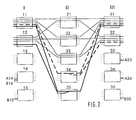
- Figure 1 shows a switching matrix in three stages of five switching modules each with currently used connections between the switching modules of the three stages.
- the Switching matrix consists of an input stage (I) with five switching modules 11, 12, 13, 14, and 15, an intermediate stage (II) with five switching modules 21, 22, 23, 24 and 25 and an output stage (III) with five switching modules 31, 32, 33, 34 and 35.
- Each of the five switching modules of the input (I) and the Output stage (III) is with each of the five switching modules of intermediate stage (II) connected via intermediate lines, not shown in the figure. Shown However, are connections that run over these intermediate lines, so that some intermediate lines become indirectly recognizable.
- the Between lines are between input stage (I) and intermediate stage (II) and between intermediate stage (II) and output stage (III).
- An intermediate line always exists between an output of a switching module of a stage and one input of a switching module of an adjacent stage.
- Such Intermediate line is e.g. between the switching modules 11 and 21 used.
- the switching modules each have five inputs and five outputs.
- An input of a switching module can be within the Switching modules in a selectable manner with at least one output of the same Switch modules are connected.
- An output of a switching module can also selectable with at least one input of the same switching module get connected.
- a switching module can have up to five independent modules Connections between one of its entrances and one of its Switch outputs at the same time.
- the switching modules 11 and 31 have one such a switching state.
- Switching modules of the switching matrix is a direct connection of the on and Exits by horizontal lines between the inputs and outputs shown. This is only intended to be a simple illustration.
- connections described at the outset are also possible the data received from the switching matrix on one of its inputs duplicated and sent in parallel to several of its outlets.
- constellations are called point-to-multipoint connections or “Multicast connections” referred to.
- Multicast connections are in the Figures made with thick, dashed lines.
- Such a “multicast connection” is e.g. switched in the switching module 24, the input side too Switching module 11 and on the output side leads to the switching modules 31 and 32.
- Another “multicast connection” leads from input A14 of the Switch module 14 via the switch module 24 to the output A33 of the Switch module 33 and to output A34 of switch module 34.
- Duplicate data streams are preferably on different Transfer trunk groups. These trunk groups then lead to incoming data streams on different switching modules of the Input stage (I) or begin for outgoing data streams different switching modules of the output stage (III).
- "Merge connections" are advantageous already in switching modules of the Intermediate stage (II) interconnected to only intermediate lines between Input (I) and intermediate (II) and not between intermediate (II) and Load output stage (III) with duplicated data streams. It is the same useful, the "multicast connections" only in the switching modules of the Intermediate stage (II) to split, because only the intermediate lines between Intermediate (II) and output stage (III) must carry duplicated data streams.
- Coupling of "merge connections” and splitting of "Multicast connections” can also be used in switching modules of other levels Switching matrix take place, especially also in switching matrixes with more levels than in the switching matrix shown in Figure 1. In any case, one is possible early coupling and splitting as late as possible is advantageous.
- FIG. 1 shows that Switch module 24 that through the lower utilization of the number of inputs compared to the number of outputs only the output to Switch module 35 remains usable. This enables the connection a between Switch module 12 and 24 only on the switch module 35 and its Outputs are continued, but not e.g. to the exits of the others Switching modules of the output stage (III).
- the part leading to intermediate (II) This "unicast connection" is indicated by a dash-dotted, thin line Figure 1 shown. A blockage occurs within the switching matrix, if the dash-dotted line in Figure 1 because of a connection request Connection a shown to an output of the switching modules 31- 34 shall be.
- the object of the invention is point-to-multipoint connections in a switching matrix of the type mentioned and multipoint-to-point connections under Taking into account the respective blocking probability.
- a symmetrical number of inputs and of Outputs of a switching module to be used for connections by a "Merge connection” a switching module with an asymmetrically higher one Load on the outputs and a switching module for a "multicast connection” is selected with an asymmetrically higher load on the inputs.
- an asymmetry parameter for each switching module led to the "merge” and “multicast connections” reversed impact proportionally.
- the asymmetry parameter could e.g. are a number, each the difference between the two Number of inputs and outputs used for "merge connections” increased or is reduced for "multicast connections”.
- a symmetrical one A switching module is loaded when it is loaded.
- the asymmetry parameter is kept as small as possible.
- Other approaches to forming the asymmetry parameter are possible, but are not explained in more detail here.
- the number too occupying inputs and outputs and already occupied inputs and outputs of a Switching modules are represented by a two-dimensional vector, whose difference vector consists of two elements that are as large as possible should.
- the switching module 24 splits the multicast connection from Switch module 11 to the switch module 31 and 32. This results in an asymmetrically higher load on the output side and from the difference one occupied input and two occupied outputs Asymmetry parameter with the value minus one.
- the switching module 25 is has an asymmetrically higher load on the input side and has one Asymmetry parameter with the value plus one, formed from the difference of two occupied inputs and one occupied output.
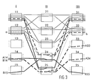
- the switching matrix in FIG. 2 should have input A14 with the Outputs A33 and A34 through a "multicast connection", hereinafter referred to as Called “multicast connection A", connect.
- the "multicast connection A” loads the splitting switch module asymmetrically and on the output side influences its asymmetry parameter by adding the value plus 1, the difference between an occupied input and two occupied Exits.
- the "multicast connection A” from one Switching module can be split, which by “merge connections” is asymmetrically loaded higher on the input side. Therefore, the "multicast connection A "over the switching module 25, so that there are the same
- the number of inputs and outputs are load-carrying and the Asymmetry parameters of switching module 25 by adding the value plus one to zero.
- the asymmetrically loaded switching modules in a coupling network determined, in Figure 1, these are the switching modules 24 and 25. Then determined whether the asymmetry in these switching modules are reduced can by unbalanced loading connections in other switching modules outsourced and continues to compensate for its own asymmetry Connections from other switching modules can be taken over. For the switching state in FIG. 1, this analysis shows that in switching module 24 a "multicast” by a “merge connection” and in switching module 25 one "Merge" must be replaced by a "multicast connection".
- the Asymmetry in switching module 24 is caused by switching the "multicast connection A "reduced to the switching module 23 and at the same time the possibility created to perform a "merge connection” via the switching module 24, the which can then still compensate for asymmetry.
- This will the "merge connection B” in a further step of switching module 25 Switching module 24 rearranged.
- the Asymmetries in the switching modules 23 and 25 eliminated by the "Multicast connection A” shifted from switching module 23 to switching module 25 becomes. This then results in a switching state, as shown in FIG. 3, with its advantages already described.
- the method according to the invention can be applied to any switching network apply. Because in the representation of the embodiments and the Figures are basic representations.
Landscapes
- Engineering & Computer Science (AREA)
- Computer Networks & Wireless Communication (AREA)
- Data Exchanges In Wide-Area Networks (AREA)
Abstract
Description
Die vorliegende Erfindung betrifft ein Verfahren zum Aufbau von Punkt-zu-Mehrpunkt-Verbindungen und Mehrpunkt-zu-Punkt-Verbindungen in einem Koppelfeld gemäß dem Oberbegriff des Anspruchs 1, ein Koppelfeld hierfür gemäß dem Oberbegriff des Anspruches 2, eine Steuereinrichtung hierfür gemäß dem Oberbegriff des Anspruches 3 und eine Vermittlungsstelle hierfür gemäß dem Oberbegriff des Anspruches 4The present invention relates to a method for establishing point-to-multipoint connections and multipoint-to-point connections in one Switching matrix according to the preamble of claim 1, a switching matrix for this according to the preamble of claim 2, a control device therefor according to the preamble of claim 3 and an exchange therefor according to the preamble of claim 4
Die Aufspaltung einer ankommenden Verbindungsleitung in einem Koppelfeld zu mehreren weiterführenden Verbindungsleitungen und die Zusammenkopplung von mehreren ankommenden Verbindungsleitungen in einem weiteren Koppelfeld zu einer gemeinsamen weiterführenden Verbindungsleitung sind aus der ITU-T Recommendation G.841 (DRAFT) "Types and Characteristics of SDH Network Protection Architectures", Version April 1995, Figur 5-7 (S. 51) auf dem Gebiet der SDH-Technik (Synchrone Digitale Hierarchie) bekannt. In den dort dargestellten Koppelfeldern wird je ein Koppelfeldeingang mit mehreren Koppelfeldausgängen durch eine Punkt-zu-Mehrpunkt-Verbindung und mehrere Koppelfeldeingänge mit einem Koppelfeldausgang durch eine Mehrpunkt-zu-Punkt-Verbindung verbunden. Die dargestellte Verwendung mindestens zweier unterschiedlicher und unabhängiger, also redundanter Verbindungswege erhöht die Übertragungssicherheit in Telekommunikationsnetzwerken oder Teilen davon. Ein durch Pfeile angedeutetes erstes Paar aus Datenquelle und Datensenke ist über ein erstes Koppelfeld ("Matrix Connection"), zwei redundante Übertragungswegpaare und ein zweites Koppelfeld ("Matrix Connection") mit einem zweiten Paar aus Datenquelle und Datensenke verbunden. Die genannten Koppelfelder sind Teile von SDH-Netzknoten, sogenannten "Crossconnects". Die paarweise Anordnung der Übertragungswege wird hier für eine Übertragung im Vollduplexbetrieb benötigt. Für eine Übertragung im Halbduplexbetrieb oder für eine unidirektionale Übertragung wäre nur je ein Kanal der Übertragungswegpaare erforderlich. Das zur Datenübertragung aktive Übertragungswegpaar wird als SNCw-Verbindung (Subnetwork Connection working) bezeichnet, das redundante Übertragungswegpaar als SNCp-Verbindung (Subnetwork Connection protection). Die Übertragung in einer Richtung auf je einem Kanal der gedoppelten Übertragungswegpaare wird im folgenden dargestellt. In der Gegenrichtung wird sinngemäß umgekehrt übertragen.ITU-T Recommendation G.841 (DRAFT) "Types and Characteristics of SDH Network Protection Architectures describes the splitting of an incoming connection line in a switching matrix into several connecting cables and the coupling of several incoming connecting cables in a further switching matrix to a common connecting cable "version April 1995 Figure 5-7 (page 51) in the field of SDH technology (S ynchrone D igital H ierarchie) known. In the switching matrixes shown there, one switching matrix input is connected to several switching matrix outputs by a point-to-multipoint connection and several switching matrix inputs are connected to one switching matrix output by a multiple-point-to-point connection. The illustrated use of at least two different and independent, that is redundant connection paths increases the transmission security in telecommunication networks or parts thereof. A first pair of data source and data sink indicated by arrows is connected to a second pair of data source and data sink via a first switching matrix ("matrix connection"), two redundant transmission path pairs and a second switching matrix ("matrix connection"). The switching networks mentioned are parts of SDH network nodes, so-called "crossconnects". The paired arrangement of the transmission paths is required here for transmission in full duplex mode. For a transmission in half duplex mode or for a unidirectional transmission, only one channel of the transmission path pairs would be required. The active transmission path for data transmission pair is referred to as SNCw compound (S ub n etwork C onnection w orking), the redundant transmission path pair as SNCP compound (S ub n etwork C onnection p rotection). The transmission in one direction on each channel of the double transmission path pairs is shown below. In the opposite direction, transmission is carried out in reverse.
Ein von der ersten Datenquelle zu der zweiten Datensenke zu übertragender Datenstrom wird von dem ersten Koppelfeld dupliziert und der Datenstrom und sein Duplikat parallel auf je einem Kanal der redundanten Übertragungswege SNCp und SNCw zur Datensenke versandt. Unmittelbar vor der Datensenke werden der Datenstrom und dessen Duplikat von dem zweiten Koppelfeld auf den redundanten Übertragungswegen empfangen und zusammengekoppelt. Dabei werden Datenstrom und Duplikat auf ihre Qualität hin überprüft, so daß daraus, wenn es möglich ist, ein fehlerfrei empfangener Datenstrom ausgewählt und der Datensenke zugeleitet werden kann. Wenn nicht beide redundanten Übertragungswege zugleich ausfallen oder Störungen aufweisen, kann der Datenstrom in oben beschriebener Weise mit hoher Übertragungsgüte und Ubertragungssicherheit von der Datenquelle zur Datensenke übertragen werden.A to be transmitted from the first data source to the second data sink Data stream is duplicated from the first switching matrix and the data stream and its duplicate in parallel on one channel of the redundant transmission paths SNCp and SNCw sent to the data sink. Immediately before the data sink the data stream and its duplicate from the second switching matrix received the redundant transmission paths and coupled together. The data stream and duplicate are checked for their quality so that from this, if possible, an error-free received data stream selected and the data sink can be sent. If not both redundant transmission paths fail at the same time or have faults, can the data stream in the manner described above with high Transmission quality and transmission security from the data source to Data sink are transmitted.
Anhand der Figur 1 wird zunächst eine Situation beschrieben, wie sie sich ohne
Anwendung des erfindungsgemäßen Verfahrens ergeben kann. Die Figur 1
zeigt ein Koppelfeld in drei Stufen aus je fünf Schaltmodulen mit momentan
genutzten Verbindungen zwischen den Schaltmodulen der drei Stufen. Das
Koppelfeld besteht aus einer Eingangsstufe (I) mit fünf Schaltmodulen 11, 12,
13, 14, und 15, einer Zwischenstufe (II) mit fünf Schaltmodulen 21, 22, 23, 24
und 25 sowie einer Ausgangsstufe (III) mit fünf Schaltmodulen 31, 32, 33, 34
und 35. Jedes der jeweils fünf Schaltmodule der Eingangs- (I) und der
Ausgangsstufe (III) ist mit jedem der fünf Schaltmodule der Zwischenstufe (II)
über in der Figur nicht dargestellte Zwischenleitungen verbunden. Dargestellt
sind jedoch Verbindungen, die über diese Zwischenleitungen laufen, so daß
dadurch einige Zwischenleitungen indirekt erkennbar werden. Die
Zwischen leitungen liegen also zwischen Eingangsstufe (I) und Zwischenstufe (II)
und zwischen Zwischenstufe (II) und Ausgangsstufe (III). Eine Zwischenleitung
besteht immer zwischen je einem Ausgang eines Schaltmodules einer Stufe und
je einem Eingang eines Schaltmodules einer benachbarten Stufe. Eine solche
Zwischenleitung wird in Figur 1 z.B. zwischen den Schaltmodulen 11 und 21
benutzt.With reference to FIG. 1, a situation is first described as it is without
Application of the method according to the invention can result. Figure 1
shows a switching matrix in three stages of five switching modules each with currently
used connections between the switching modules of the three stages. The
Switching matrix consists of an input stage (I) with five
Die Schaltmodule haben im dargestellten Beispiel jeweils fünf Eingänge und
fünf Ausgänge. Ein Eingang eines Schaltmodules kann innerhalb des
Schaltmodules in wählbarer Weise mit mindestens einem Ausgang desselben
Schaltmodules verbunden werden. Ein Ausgang eines Schaltmodules kann
ebenfalls wählbar mit mindestens einem Eingang desselben Schaltmodules
verbunden werden. Ein Schaltmodul kann jeweils bis zu fünf unabhängige
Verbindungen zwischen je einem seiner Eingänge und je einem seiner
Ausgänge zugleich schalten. Die Schaltmodule 11 und 31 weisen einen
solchen Schaltzustand auf. In diesen wie auch den meisten anderen
Schaltmodulen des Koppelfeldes ist eine direkte Durchschaltung der Ein- und
Ausgänge durch horizontale Linien zwischen den Ein- und Ausgängen
dargestellt. Dies soll lediglich einer einfachen Veranschaulichung dienen.In the example shown, the switching modules each have five inputs and
five outputs. An input of a switching module can be within the
Switching modules in a selectable manner with at least one output of the same
Switch modules are connected. An output of a switching module can
also selectable with at least one input of the same switching module
get connected. A switching module can have up to five independent modules
Connections between one of its entrances and one of its
Switch outputs at the same time. The
Wenn eine Verbindung durch das Koppelfeld hindurch von nur einem Eingang nur eines Schaltmodules der Eingangsstufe (I) zu nur einem Ausgang nur eines Schaltmodules der Ausgangsstufe (III) führt, so wird diese umkehrbar eindeutige Verbindung auch eine "Unicast-Verbindung" genannt. Die in Figur 1 geschalteten "Unicast-Verbindungen" sind durch dünne durchgezogene Linien dargestellt.If there is a connection through the switching matrix from only one entrance only one switching module of the input stage (I) to only one output only one Switching modules of the output stage (III) leads, this is reversible unique connection also called a "unicast connection". In the Figure 1 switched "unicast connections" are by thin solid lines are shown.
Möglich sind jedoch auch die eingangs beschriebenen Verbindungen, bei
denen die vom Koppelfeld auf einem seiner Eingänge empfangenen Daten
dupliziert und parallel auf mehrere seiner Ausgänge versandt werden. Hier
werden derartige Konstellationen als Punkt-zu-Mehrpunkt-Verbindungen oder
"Multicast-Verbindungen" bezeichnet. "Multicast-Verbindungen" sind in den
Figuren mit dicken, gestrichelten Linien ausgeführt. Eine solche "Multicast-Verbindung"
ist z.B. im Schaltmodul 24 geschaltet, die eingangsseitig zu
Schaltmodul 11 und ausgangsseitig zu den Schaltmodulen 31 und 32 führt.
Eine weitere "Multicast-Verbindung" führt vom Eingang A14 des
Schaltmodules 14 über das Schaltmodul 24 zum Ausgang A33 des
Schaltmodules 33 und zum Ausgang A34 des Schaltmodules 34.However, the connections described at the outset are also possible
the data received from the switching matrix on one of its inputs
duplicated and sent in parallel to several of its outlets. Here
such constellations are called point-to-multipoint connections or
"Multicast connections" referred to. "Multicast connections" are in the
Figures made with thick, dashed lines. Such a "multicast connection"
is e.g. switched in the
In ähnlicher Weise können auch mehrere Eingänge eines Koppelfeldes mit
einem einzigen seiner Ausgänge zu einer hier als Mehrpunkt-zu-Punkt-Verbindung
oder auch "Merge-Verbindung" bezeichneten Verbindung
zusammengekoppelt werden. "Merge-Verbindungen" werden in den Figuren
mit dicken, durchgezogenen Linien dargestellt. Das Schaltmodul 25 koppelt
eine solche "Merge-Verbindung" zusammen zwischen seinen Eingängen zu
den Schaltmodulen 11 und 12 hin und seinem Ausgang zu Schaltmodul 31
hin. Eine weitere "Merge -Verbindung" besteht zwischen den Eingängen B14
und B15 der Schaltmodule 14 bzw. 15 über das Schaltmodul 25 zum
Ausgang B35 des Schaltmodules 35. Bei einer "Merge-Verbindung" werden
der Datenstrom und dessen Duplikat, die eingangsseitig vom Koppelfeld
parallel empfangen worden sind, vom zusammenkoppelnden Schaltmodul auf
ihre Qualität hin überprüft. Wenn der Datenstrom oder dessen Duplikat als
fehlerfrei erkannt worden sind, wird ein einziger fehlerfreier Datenstrom
ausgewählt und an einen einzigen Ausgang weitergeleitet. Wenn weder
Datenstrom noch Duplikat fehlerfrei sind, könnte auch ein fehlerbehafteter,
möglicherweise zusätzlich wegen seiner Fehlerhaftigkeit speziell markierter,
Datenstrom dem Ausgang zugeführt werden.In a similar way, several inputs of a switching matrix can also be used
one of its outputs to one here as a multipoint-to-point connection
or also called "merge connection" connection
be coupled together. "Merge connections" are shown in the figures
shown with thick, solid lines. The
Duplizierte Datenströme werden vorzugsweise auf unterschiedlichen Leitungsbündeln übertragen. Diese Leitungsbündel münden dann für ankommende Datenströme auf unterschiedlichen Schaltmodulen der Eingangsstufe (I) oder beginnen für abgehende Datenströme auf unterschiedlichen Schaltmodulen der Ausgangsstufe (III). "Merge-Verbindungen" werden vorteilhaft bereits in Schaltmodulen der Zwischenstufe (II) zusammengeschaltet, um nur Zwischenleitungen zwischen Eingangs- (I) und Zwischenstufe (II) und nicht zwischen Zwischen- (II) und Ausgangsstufe (III) mit duplizierten Datenströmen zu belasten. Ebenso ist es nützlich, die "Multicast-Verbindungen" erst in den Schaltmodulen der Zwischenstufe (II) aufzusplitten, da so nur die Zwischenleitungen zwischen Zwischen- (II) und Ausgangsstufe (III) duplizierte Datenströme führen müssen. Zusammenkopplung von "Merge-Verbindungen" und Aufsplittung von ,,Multicast-Verbindungen" können auch in Schaltmodulen anderer Stufen eines Koppelfeldes stattfinden, insbesondere auch bei Koppelfeldern mit mehr Stufen als im dargestellten Koppelfeld aus Figur 1. Auf jeden Fall ist eine möglichst frühe Zusammenkopplung und eine möglichst späte Aufsplittung vorteilhaft.Duplicate data streams are preferably on different Transfer trunk groups. These trunk groups then lead to incoming data streams on different switching modules of the Input stage (I) or begin for outgoing data streams different switching modules of the output stage (III). "Merge connections" are advantageous already in switching modules of the Intermediate stage (II) interconnected to only intermediate lines between Input (I) and intermediate (II) and not between intermediate (II) and Load output stage (III) with duplicated data streams. It is the same useful, the "multicast connections" only in the switching modules of the Intermediate stage (II) to split, because only the intermediate lines between Intermediate (II) and output stage (III) must carry duplicated data streams. Coupling of "merge connections" and splitting of "Multicast connections" can also be used in switching modules of other levels Switching matrix take place, especially also in switching matrixes with more levels than in the switching matrix shown in Figure 1. In any case, one is possible early coupling and splitting as late as possible is advantageous.
Aus der Anordnung der Verbindungen in Figur 1 ergibt sich für das
Schaltmodul 24, daß durch die geringere Ausnutzung der Anzahl der Eingänge
gegenüber der Anzahl der Ausgänge nur noch der Ausgang zum
Schaltmodul 35 nutzbar bleibt. Dadurch kann die Verbindung a zwischen
Schaltmodul 12 und 24 nur noch auf das Schaltmodul 35 und dessen
Ausgänge weitergeführt werden, nicht aber z.B. auf die Ausgänge der anderen
Schaltmodule der Ausgangsstufe (III). Der zur Zwischenstufe (II) führende Teil
dieser "Unicast-Verbindung" ist durch eine strichpunktierte, dünne Linie in
Figur 1 dargestellt. Es tritt eine Blockierung innerhalb des Koppelfeldes auf,
wenn wegen eines Verbindungswunsches die in Figur 1 strichpunktiert
dargestellte Verbindung a auf einen Ausgang der Schaltmodule 31- 34 geführt
werden soll.The arrangement of the connections in FIG. 1 shows that
Eine ähnliche Problematik ergibt sich für die einzige noch nicht belegte
Ausgangsleitung b aus dem Schaltmodul 32 heraus. Diese Leitung kann mit
der in Figur 1 dargestellten Schaltanordnung über das Schaltmodul 25 erreicht
werden. Das Schaltmodul 25 jedoch hat in Figur 1 nur noch einen einzigen
Eingang frei, nämlich den zu Schaltmodul 13. Bei einem Verbindungswunsch
von einem der freien Eingänge der übrigen Schaltmodule der Eingangsstufe (I)
zur freien Ausgangsleitung b hin tritt eine weitere Blockierung auf.A similar problem arises for the only one not yet documented
Output line b out of the
Aufgabe der Erfindung ist es, in einem Koppelfeld der genannten Art Punkt-zu-Mehrpunkt-Verbindungen und Mehrpunkt-zu-Punkt-Verbindungen unter Berücksichtigung der jeweiligen Blockierungswahrscheinlichkeit aufzubauen.The object of the invention is point-to-multipoint connections in a switching matrix of the type mentioned and multipoint-to-point connections under Taking into account the respective blocking probability.
Diese Aufgabe wird durch die technische Lehre des Anspruchs 1, des Anspruchs 2, des Anspruchs 3 und des Anspruchs 4 gelöst. Weitere vorteilhafte Ausgestaltungen der Erfindung sind dem abhängigen Anspruch und der Beschreibung zu entnehmen.This object is achieved by the technical teaching of claim 1 Claim 2, claim 3 and claim 4 solved. More beneficial Embodiments of the invention are the dependent claim and the See description.
Im folgenden werden die Erfindung und ihre Vorteile anhand eines Ausführungsbeispiels unter Zuhilfenahme der Zeichnungen dargestellt.
- Figur 1
- zeigt ein Beispiel eines Koppelfeldes mit einem der möglichen Schaltzustände, wie er sich ohne Anwendung des erfindungsgemäßen Verfahrens ergeben kann.
- Figur 2
- zeigt das Beispiel des aus Figur 1 bekannten Koppelfeldes mit einem gegenüber Figur 1 veränderten Schaltzustand, wie er vor dem in Figur 1 gezeigten Schaltzustand bestanden haben könnte.
- Figur 3
- zeigt das Beispiel des aus Figur 1 bekannten Koppelfeldes mit einem gegenüber Figur 1 veränderten Schaltzustand, bei dem das erfindungsgemäße Verfahren vorteilhaft angewendet worden ist.
- Figure 1
- shows an example of a switching matrix with one of the possible switching states, as can arise without using the method according to the invention.
- Figure 2
- shows the example of the switching matrix known from FIG. 1 with a switching state that has changed compared to FIG. 1, as it might have existed before the switching state shown in FIG. 1.
- Figure 3
- shows the example of the switching matrix known from FIG. 1 with a switching state which has been changed compared to FIG. 1 and in which the method according to the invention has been advantageously used.
Bei "Multicast-Verbindungen" werden mehr Ausgänge als Eingänge eines Schaltmodules benutzt. Andererseits werden bei "Merge-Verbindungen" mehr Ein- als Ausgänge eines Schaltmodules benötigt. "Merge-" und "Multicast-Verbindungen" belasten ein Schaltmodul also bezüglich der Anzahl seiner genutzten Ein- und Ausgänge in entgegengesetzter Weise unsymmetrisch. Im folgenden werden die Begriffe "Symmetrie" und "Unsymmetrie" im Zusammenhang mit der Anzahl genutzter Ein- und Ausgänge eines Schaltmodules verwendet. Es wird nun erfindungsgemäß vorgeschlagen, eine möglichst gleich große, symmetrische Anzahl von Eingängen und von Ausgängen eines Schaltmodules für Verbindungen zu nutzen, indem für eine "Merge-Verbindung" ein Schaltmodul mit einer unsymmetrisch höheren Belastung der Ausgänge und für eine "Multicast-Verbindung" ein Schaltmodul mit einer unsymmetrisch höheren Belastung der Eingänge gewählt wird. Dazu wird in vorteilhafter Weise ein Unsymmetrieparameter für jedes Schaltmodul geführt, auf den sich "Merge-" und ,,Multicast-Verbindungen" umgekehrt proportional auswirken. Es könnte sich bei dem Unsymmetrieparameter z.B. um eine Zahl handeln, die jeweils um die um die Differenz zwischen den Anzahlen genutzter Ein- und Ausgänge bei "Merge-Verbindungen" vergrößert bzw. bei "Multicast-Verbindungen" verkleinert wird. Eine symmetrische Belastung eines Schaltmodules wird dann erreicht, wenn dieser Unsymmetrieparameter dem Betrage nach möglichst klein gehalten wird. Andere Vorgehensweisen zur Bildung des Unsymmetrieparameters sind möglich, werden aber hier nicht näher erläutert. Es könnte z.B. die Anzahl zu belegender Ein- und Ausgänge und bereits belegter Ein- und Ausgänge eines Schaltmodules durch je einen zweidimensionalen Vektor dargestellt werden, deren Differenzvektor aus zwei möglichst gleich großen Elementen bestehen soll.With "multicast connections" more outputs than inputs of one Switch modules used. On the other hand, with "merge connections" more Inputs as outputs of a switching module required. "Merge" and "Multicast connections" load a switching module in terms of the number of its used inputs and outputs in opposite ways asymmetrically. in the The following are the terms "symmetry" and "asymmetry" in the Relationship to the number of inputs and outputs used Switching modules used. It is now proposed according to the invention, a symmetrical number of inputs and of Outputs of a switching module to be used for connections by a "Merge connection" a switching module with an asymmetrically higher one Load on the outputs and a switching module for a "multicast connection" is selected with an asymmetrically higher load on the inputs. To is advantageously an asymmetry parameter for each switching module led to the "merge" and "multicast connections" reversed impact proportionally. The asymmetry parameter could e.g. are a number, each the difference between the two Number of inputs and outputs used for "merge connections" increased or is reduced for "multicast connections". A symmetrical one A switching module is loaded when it is loaded The asymmetry parameter is kept as small as possible. Other approaches to forming the asymmetry parameter are possible, but are not explained in more detail here. For example, the number too occupying inputs and outputs and already occupied inputs and outputs of a Switching modules are represented by a two-dimensional vector, whose difference vector consists of two elements that are as large as possible should.
Im folgenden wird zunächst die Anwendung des erfindungsgemäßen Verfahrens dargestellt anhand einer Fortentwicklung des Schaltzustandes von Figur 2 in den Schaltzustand in Figur 3. Beide Figuren zeigen das Beispiel des aus Figur 1 bekannten Koppelfeldes mit jeweils veränderten Schaltzuständen. Der Schaltzustand in Figur 2 stellt eine mögliche Vorstufe der Schaltzustände von Figur 1 oder Figur 3 dar und kann ohne besonderes Zutun sowohl in den ungünstigen Schaltzustand von Figur 1 münden als auch vorteilhaft durch Anwendung des erfindungsgemäßen Verfahrens in den Schaltzustand von Figur 3 weiterentwickelt werden.The following is the application of the invention Process illustrated based on a further development of the switching state of Figure 2 in the switching state in Figure 3. Both figures show the example of the switching network known from Figure 1, each with changed switching states. The switching state in FIG. 2 represents a possible preliminary stage of the switching states of Figure 1 or Figure 3 and can be done in the unfavorable switching state of Figure 1 also lead to advantageous Application of the method according to the invention in the switching state of Figure 3 can be further developed.
In Figur 2 splittet das Schaltmodul 24 die Multicast-Verbindung von
Schaltmodul 11 zu den Schaltmodul 31 und 32 auf. Dadurch ergibt sich
ausgangsseitig eine unsymmetrisch höhere Belastung und aus der Differenz
von einem belegten Eingang und zwei belegten Ausgängen ein
Unsymmetrieparameter mit dem Wert minus eins. Das Schaltmodul 25 ist
eingangsseitig unsymmetrisch höher belastet und hat einen
Unsymmetrieparameter mit dem Wert plus eins, gebildet aus der Differenz von
zwei belegten Eingängen und einem belegten Ausgang.In Figure 2, the switching
Nun soll von dem Koppelfeld eine "Merge-Verbindung" zwischen
Eingängen B14 und B15 und dem Ausgang B35, im folgenden als "Merge-Verbindung
B" bezeichnet, hergestellt werden. Erfindungsgemäß wird für eine
symmetrische Belastung der Schaltmodule gesorgt. Die besagte eingangsseitig
höher belastende "Merge-Verbindung" soll von einem Schaltmodul
zusammengeführt werden, das durch "Multicast-Verbindungen" ausgangsseitig
unsymmetrisch höher belastet ist. Deshalb wird nach dem erfindungsgemäßen
Verfahren die "Merge-Verbindung B" über das Schaltmodul 24 geführt. Der
Unsymmetrieparameter von Schaltmodul 24 nimmt dann den Wert null an, da
wegen der neu etablierten "Merge-Verbindung B" zum bisherigen Wert minus
eins der Wert plus eins addiert wird, nämlich die Differenz von zwei belegten
Eingängen und einem belegten Ausgang.Now there should be a "merge connection" between the switching matrix
Inputs B14 and B15 and output B35, hereinafter referred to as "merge connection
B "can be produced. According to the invention, for a
symmetrical loading of the switching modules. The said input side
"Merge connection", which is more stressful, is supposed to be from a switching module
can be merged, that by "multicast connections" on the output side
is loaded asymmetrically higher. Therefore, according to the invention
The "merge connection B" is routed via the
Weiterhin soll das Koppelfeld in Figur 2 den Eingang A14 mit den
Ausgängen A33 und A34 durch eine "Multicast-Verbindung", im folgenden als
"Multicast-Verbindung A" bezeichnet, verbinden. Die "Multicast-Verbindung A"
belastet das aufsplittende Schaltmodul ausgangsseitig unsymmetrisch und
beeinflußt dessen Unsymmetrieparameter durch die Addition des Wertes
plus 1, der Differenz von einem belegten Eingang und zwei belegten
Ausgängen. Erfindungsgemäß soll die "Multicast-Verbindung A" von einem
Schaltmodul aufgesplitten werden, das durch "Merge-Verbindungen"
eingangsseitig unsymmetrisch höher belastet ist. Deshalb wird die "Multicast-Verbindung
A" über das Schaltmodul 25 geführt, so daß dort die gleichen
Anzahlen von Ein- und Ausgängen lastführend sind und der
Unsymmetrieparameter von Schaltmodul 25 durch Addition des Wertes plus
eins zu null wird.Furthermore, the switching matrix in FIG. 2 should have input A14 with the
Outputs A33 and A34 through a "multicast connection", hereinafter referred to as
Called "multicast connection A", connect. The "multicast connection A"
loads the splitting switch module asymmetrically and on the output side
influences its asymmetry parameter by adding the value
plus 1, the difference between an occupied input and two occupied
Exits. According to the "multicast connection A" from one
Switching module can be split, which by "merge connections"
is asymmetrically loaded higher on the input side. Therefore, the "multicast connection
A "over the switching
Die erfindungsgemäß hergestellten und oben beschriebenen "Multicast-Verbindung A" und "Merge-Verbindung B" sind in Figur 3 dargestellt. Nach außen hin weist das Koppelfeld in Figur 3 eine gegenüber Figur 1 unveränderte Beziehung zwischen den Eingangsschnittstellen der Eingangsstufe (I) und den Ausgangsschnittstellen der Ausgangsstufe (III) auf, d.h. es sind in Figur 1 und in Figur 3 dieselben Eingänge von Schaltmodulen der Eingangsstufe (I) über koppelfeldinterne Verbindungen mit denselben Ausgängen von Schaltmodulen der Ausgangsstufe (III) verbunden.The multicast connection produced according to the invention and described above A "and" Merge connection B "are shown in Figure 3. After on the outside, the switching matrix in FIG. 3 has one compared to FIG. 1 unchanged relationship between the input interfaces of the Input stage (I) and the output interfaces of the output stage (III), i.e. in FIG. 1 and in FIG. 3 there are the same inputs of switching modules the input stage (I) via internal network connections with the same Outputs of switching modules of the output stage (III) connected.
Die im Zusammenhang mit Figur 1 eingangs erwähnte Verbindung a, die dort
von Schaltmodul 12 über Schaltmodul 24 zu Schaltmodul 35 führen kann und
nur auf dessen vier Ausgänge schaltbar ist, ist auch in Figur 3 wieder
dargestellt. Dort könnte jedoch die Verbindung a sowohl auf die freien
Ausgänge des Schaltmodules 33 als auch des Schaltmodules 34 weitergeführt
werden. Insgesamt sind dann für den Eingang der Verbindung a acht
Ausgänge des Koppelfeldes erreichbar. Die Blockierungswahrscheinlichkeit ist
damit gegenüber dem Schaltzustand in Figur 1 halbiert.The connection a mentioned at the beginning in connection with FIG. 1, which is there
can lead from switching
Auch die einleitend genannte Verbindung von Schaltmodul 25 zum Ausgang b
ist in Figur 3 wieder aufgegriffen. Durch den Schaltzustand in Figur 3 kann der
Ausgang b nunmehr von den fünf Eingängen des Schaltmodules 13 und
zusätzlich von den vier freien Eingängen des Schaltmodules 15 erreicht
werden. Hier ist die Blockierungswahrscheinlichkeit im Verhältnis fünf zu neun
verringert, also ebenfalls nahezu halbiert. The above-mentioned connection from the switching
Neben der beschriebenen Fortentwicklung des Schaltzustandes wie in Figur 2 in den Schaltzustand wie in Figur 3 ist es mit dem erfindungsgemäßen Verfahren auch möglich, den Schaltzustand aus Figur 1 in den Schaltzustand der Figur 3 im Rahmen eines sogenannten ,,Rearrangements" zu überführen. Bei einem solchen "Rearrangement" wird für eine umzugruppierende Verbindung zunächst innerhalb des Koppelfeldes ein paralleler Verbindungspfad über andere Schaltmodule hergestellt, auf den nach Überprüfung seiner Funktionsfähigkeit umgeschaltet wird. Dann wird der bisherige Verbindungspfad freigegeben. Ein ,,Rearrangement" des in Figur 1 dargestellten Schaltzustandes wird im folgenden beschrieben.In addition to the further development of the switching state as described in FIG. 2 in the switching state as in Figure 3 it is with the invention Process also possible, the switching state of Figure 1 in the switching state to transfer the figure 3 as part of a so-called "rearrangement". With such a "rearrangement" is to be regrouped First a parallel connection within the switching matrix Connection path established via other switching modules, on the after Checking its functionality is switched. Then the previous connection path released. A "rearrangement" of the in FIG Switching state shown is described below.
Bei einem "Rearrangement" nach dem erfindungsgemäßen Verfahren werden
zunächst die unsymmetrisch belasteten Schaltmodule in einem Koppel netz
ermittelt, in Figur 1 sind dies die Schaltmodule 24 und 25. Dann wird
festgestellt, ob die Unsymmetrie in diesen Schaltmodulen verringert werden
kann, indem unsymmetrisch belastende Verbindungen in andere Schaltmodule
ausgelagert und weiterhin die eigene Unsymmetrie ausgleichende
Verbindungen von anderen Schaltmodulen übernommen werden können.
Diese Analyse ergibt für den Schaltzustand in Figur 1, daß in Schaltmodul 24
eine "Multicast-" durch eine "Merge-Verbindung" und in Schaltmodul 25 eine
"Merge-" durch eine "Multicast-Verbindung" ersetzt werden muß. Die
Unsymmetrie in Schaltmodul 24 wird durch Umlegen der "Multicast-Verbindung
A" auf das Schaltmodul 23 reduziert und zugleich die Möglichkeit
geschaffen, eine "Merge-Verbindung" über das Schaltmodul 24 zu führen, die
dessen dann noch vorhandene Unsymmetrie kompensieren kann. Dazu wird
die "Merge-Verbindung B" in einem weiteren Schritt von Schaltmodul 25 auf
Schaltmodul 24 umgeordnet. In einem abschließenden Schritt werden die
Unsymmetrien in den Schaltmodulen 23 und 25 beseitigt, indem die
,,Multicast-Verbindung A" von Schaltmodul 23 auf Schaltmodul 25 verlagert
wird. Es ergibt sich dann ein Schaltzustand, wie in Figur 3 gezeigt, mit seinen
bereits beschriebenen Vorteilen.In a "rearrangement" according to the inventive method
First, the asymmetrically loaded switching modules in a coupling network
determined, in Figure 1, these are the switching
Wie oben aufgezeigt, ist ein "Rearrangement" aufwendig und insbesondere bei Crossconnects in der SDH-Technik sehr zeitintensiv. Deshalb ist es besonders vorteilhaft, von vornherein den Schaltzustand durch das oben anhand von Figur 2 und 3 beschriebene, erfindungsgemäße Verfahren so zu gestalten, daß damit die Blockierungswahrscheinlichkeit und folglich die Wahrscheinlichkeit für ein "Rearrangement" gering gehalten wird.As shown above, a "rearrangement" is complex and in particular with Crossconnects in SDH technology are very time-consuming. That's why it's special advantageous, from the outset the switching state by the above based on Figure 2 and 3 described inventive method to design so that hence the probability of blocking and consequently the probability for a "rearrangement" is kept low.
Das erfindungsgemäße Verfahren läßt sich auf beliebige Koppelfelder anwenden. Denn bei der Darstellung der Ausführungsbeispiele und den Figuren handelt es sich um Prinzipdarstellungen.The method according to the invention can be applied to any switching network apply. Because in the representation of the embodiments and the Figures are basic representations.
Für das erfindungsgemäße Verfahren ist es weiterhin nicht relevant, daß alle Schaltmodule einer Stufe den Aufbau von "Merge-" und "Multicast-Verbindungen" erlauben, denn schon bei zweien solcher Schaltmodule in einer Stufe kann in der erfindungsgemäßen Weise vorgegangen werden.For the method according to the invention, it is also not relevant that all Switching modules of one level establishing "merge" and "multicast connections" allow, because with two such switching modules in one Step can be carried out in the manner according to the invention.
Falls eine weitere Erhöhung der Übertragungssicherheit mehr als zwei redundante Übertragungswege erfordert, kann das erfindungsgemäße Verfahren auch für den Aufbau solcher Verbindungen angewendet werden.If a further increase in transmission security is more than two Requires redundant transmission paths, the invention Procedures can also be used for the establishment of such connections.
Die Aufspaltung oder Zusammenkopplung von Übertragungswegen in Koppelfeldern im Zusammenhang mit einer Erhöhung der Übertragungssicherheit ist ebenfalls nur eine beispielhafte Anwendung des erfindungsgemäßen Verfahrens. Auch z.B. beim Aufbau von Konferenzschaltungen könnte in erfindungsgemäßer Weise vorgegangen werden.The splitting or coupling of transmission paths in Coupling fields in connection with an increase in Transmission security is also just one example of how the inventive method. Also e.g. when building Conference calls could proceed in the manner according to the invention become.
Claims (5)
Applications Claiming Priority (2)
| Application Number | Priority Date | Filing Date | Title |
|---|---|---|---|
| DE19741577A DE19741577A1 (en) | 1997-09-20 | 1997-09-20 | Methods and devices for establishing point-to-multipoint connections and multipoint-to-point connections |
| DE19741577 | 1997-09-20 |
Publications (2)
| Publication Number | Publication Date |
|---|---|
| EP0903958A2 true EP0903958A2 (en) | 1999-03-24 |
| EP0903958A3 EP0903958A3 (en) | 2001-01-24 |
Family
ID=7843084
Family Applications (1)
| Application Number | Title | Priority Date | Filing Date |
|---|---|---|---|
| EP98440174A Withdrawn EP0903958A3 (en) | 1997-09-20 | 1998-08-14 | Method and devices for establishing point-to-multipoint connections and multipoint-to-point connections |
Country Status (6)
| Country | Link |
|---|---|
| US (1) | US6418142B1 (en) |
| EP (1) | EP0903958A3 (en) |
| CN (1) | CN1213918A (en) |
| AU (1) | AU8308598A (en) |
| CA (1) | CA2245256A1 (en) |
| DE (1) | DE19741577A1 (en) |
Cited By (1)
| Publication number | Priority date | Publication date | Assignee | Title |
|---|---|---|---|---|
| EP1113627A2 (en) * | 1999-12-27 | 2001-07-04 | Alcatel USA Sourcing, L.P. | Method of determining network paths in a three stage switching matrix |
Families Citing this family (11)
| Publication number | Priority date | Publication date | Assignee | Title |
|---|---|---|---|---|
| JP2001007846A (en) * | 1999-06-18 | 2001-01-12 | Fujitsu Ltd | Frame repeater |
| US6751217B1 (en) * | 1999-10-06 | 2004-06-15 | Nortel Networks Limited | Combined selector switch and serial multi-Gb/s data pulse receiver |
| US6665726B1 (en) * | 2000-01-06 | 2003-12-16 | Akamai Technologies, Inc. | Method and system for fault tolerant media streaming over the internet |
| US7065076B1 (en) * | 2000-08-25 | 2006-06-20 | Promise Technology, Inc. | Modular scalable switching networks |
| US7342922B1 (en) * | 2001-06-18 | 2008-03-11 | Cisco Technology, Inc. | Multi-stage switching for networks |
| US7408961B2 (en) * | 2001-09-13 | 2008-08-05 | General Instrument Corporation | High speed serial data transport between communications hardware modules |
| GB0306536D0 (en) * | 2003-03-21 | 2003-04-23 | Marconi Comm Ltd | "Paths in telecommunications networks" |
| JP2007532037A (en) * | 2003-09-06 | 2007-11-08 | チーク テクノロジーズ,インク. | Strictly non-blocking multicast linear time multistage network |
| US20070058530A1 (en) * | 2005-09-14 | 2007-03-15 | Sbc Knowledge Ventures, L.P. | Apparatus, computer readable medium and method for redundant data stream control |
| US10237205B2 (en) * | 2013-06-20 | 2019-03-19 | The Boeing Company | Switch routing algorithms |
| CN108462621B (en) * | 2018-03-01 | 2020-12-29 | 航天柏克(广东)科技有限公司 | Method for communication equipment address allocation and equipment quantity statistics |
Citations (1)
| Publication number | Priority date | Publication date | Assignee | Title |
|---|---|---|---|---|
| US5451936A (en) * | 1991-06-20 | 1995-09-19 | The Johns Hopkins University | Non-blocking broadcast network |
Family Cites Families (9)
| Publication number | Priority date | Publication date | Assignee | Title |
|---|---|---|---|---|
| ATE115802T1 (en) * | 1991-07-22 | 1994-12-15 | Alcatel Nv | TELECOMMUNICATION SYSTEM FOR TRANSMISSION OF MESSAGE CELLS THROUGH SWITCHING NODES INTERCONNECTED VIA GROUPS OF TRANSMISSION LINES. |
| US5287346A (en) * | 1991-10-16 | 1994-02-15 | Carnegie Mellon University | Packet switch |
| FI90707C (en) * | 1992-04-24 | 1994-03-10 | Nokia Telecommunications Oy | Method of forming the coupling routes in a cross coupler |
| IT1255810B (en) * | 1992-08-07 | 1995-11-16 | Alcatel Italia | SWITCHING PHOTONIC CONNECTION NETWORK FOR INFORMATION DISCLOSURE |
| FR2703545B1 (en) * | 1993-03-31 | 1995-05-12 | Alcatel Nv | Asynchronous switching node dynamically distributing cells to outputs constituting a so-called irregular group. |
| JPH0955749A (en) * | 1995-08-14 | 1997-02-25 | Fujitsu Ltd | Route selecting method of cell exchange |
| KR100278016B1 (en) * | 1995-12-26 | 2001-01-15 | 윤종용 | Switching device and method of asynchronous transfer mode switching system |
| DE19605873C2 (en) * | 1996-02-17 | 2003-07-24 | Bernhard Walke | Directional radio system with decentrally controlled dynamic channel selection and dynamic capacity allocation |
| DE19610334C2 (en) * | 1996-03-18 | 2000-09-28 | Bernhard Walke | Point-to-multipoint radio system with dynamic channel selection and simultaneous operation in different frequency bands due to radio propagation |
-
1997
- 1997-09-20 DE DE19741577A patent/DE19741577A1/en not_active Withdrawn
-
1998
- 1998-08-14 EP EP98440174A patent/EP0903958A3/en not_active Withdrawn
- 1998-09-03 AU AU83085/98A patent/AU8308598A/en not_active Abandoned
- 1998-09-15 US US09/153,704 patent/US6418142B1/en not_active Expired - Fee Related
- 1998-09-18 CA CA002245256A patent/CA2245256A1/en not_active Abandoned
- 1998-09-18 CN CN98119633.0A patent/CN1213918A/en active Pending
Patent Citations (1)
| Publication number | Priority date | Publication date | Assignee | Title |
|---|---|---|---|---|
| US5451936A (en) * | 1991-06-20 | 1995-09-19 | The Johns Hopkins University | Non-blocking broadcast network |
Non-Patent Citations (2)
| Title |
|---|
| TANAKA Y ET AL: "THREE-STAGE SWITCHING NETWORKS FOR N:1 MULTICONNECTION" ELECTRONICS & COMMUNICATIONS IN JAPAN, PART I : COMMUNICATIONS, Bd. 71 (1988) Juli, Nr. 7, Seiten 66-74, XP000029338 ISSN: 8756-6621 * |
| WON-BAE PARK ET AL: "SONET/SDH MULTICAST ROUTING ALGORITHMS IN SYMMETRICAL THREE STAGE NETWORKS" PROCEEDINGS OF THE 1995 IEEE INTERNATIONAL CONFERENCE ON COMMUNICATIONS (ICC'95), SEATTLE, WA, USA, 18. - 22. Juni 1995, Seiten 1912-1917 Bd. 3, XP000535070 ISBN: 0-7803-2487-0 * |
Cited By (2)
| Publication number | Priority date | Publication date | Assignee | Title |
|---|---|---|---|---|
| EP1113627A2 (en) * | 1999-12-27 | 2001-07-04 | Alcatel USA Sourcing, L.P. | Method of determining network paths in a three stage switching matrix |
| EP1113627A3 (en) * | 1999-12-27 | 2004-05-19 | Alcatel USA Sourcing, L.P. | Method of determining network paths in a three stage switching matrix |
Also Published As
| Publication number | Publication date |
|---|---|
| AU8308598A (en) | 1999-04-15 |
| CN1213918A (en) | 1999-04-14 |
| DE19741577A1 (en) | 1999-03-25 |
| EP0903958A3 (en) | 2001-01-24 |
| US6418142B1 (en) | 2002-07-09 |
| CA2245256A1 (en) | 1999-03-20 |
Similar Documents
| Publication | Publication Date | Title |
|---|---|---|
| EP0903958A2 (en) | Method and devices for establishing point-to-multipoint connections and multipoint-to-point connections | |
| DE69023796T2 (en) | Network rearrangement procedure and system. | |
| DE60038722T2 (en) | Method for determining network paths in a three-level switching matrix | |
| DE3016706C2 (en) | ||
| EP0058750A1 (en) | Circuit arrangement for TDM-telecommunications exchanges, in particular PCM-telephone exchanges with data channels between a central control unit and decentralised control equipment | |
| EP0463215B1 (en) | Communication network for establishing a redundant link | |
| DE3023205C2 (en) | ||
| DE3513165A1 (en) | Circuit arrangement for telecommunications switching systems, in particular telephone switching systems, with devices for functional capability testing of switched connections | |
| EP0016396B1 (en) | Switching network with inverted grouping, especially for telephone switching systems | |
| DE1512947C3 (en) | Circuit arrangement for telecommunications switching systems with multi-level switching fields, in particular for telephone systems Siemens AG, 1000 Berlin and 8000 Munich | |
| DE2353325A1 (en) | INTERMEDIATE DISTRIBUTION PROCEDURE IN MULTI-STAGE COUPLING FIELDS FOR TELEVISION, IN PARTICULAR TELEPHONE SWITCHING SYSTEMS | |
| EP0016397B1 (en) | Indirectly controlled switching system, in particular telephone switching system | |
| DE2638593C2 (en) | Switching matrix with overflow switching matrix for a telecommunications, in particular telephone exchange | |
| DE2446391A1 (en) | Time multiplex coupling field arrangement - which is pulse code modulated has multiplex incoming channels coupled to multiplex output channels with modules | |
| DE4330295C2 (en) | Method and switching matrix arrangement for transmitting cells in the course of a point-to-multipoint connection in a packet switching system | |
| DE2542579A1 (en) | Coupling field for communication systems - consists of coupling multiples with same order inputs and outputs connected to four wire lines | |
| EP0280090B1 (en) | Coupling arrangement for multistage coupling fields in telecommunication exchanges, especially time division multiplex telephone exchanges with coupling multiples and interconnection lines which interconnect these multiples from coupling stage to coupling stage | |
| DE2749236C2 (en) | PCM time-division multiplex telecommunications system | |
| DE2659178C2 (en) | Coupling arrangement, in particular for the connection of time division multiplex lines | |
| DE2115378A1 (en) | Intermediate line distribution method in multi-level switching matrices from switching matrices for telecommunications, in particular telephone switching systems | |
| DE1762858B2 (en) | ||
| DE1803389B2 (en) | CIRCUIT ARRANGEMENT FOR REMOTE COMMUNICATION SYSTEMS, IN PARTICULAR TELEPHONE SWITCHING SYSTEMS, WITH A COUPLING FIELD FOR FOUR-WIRE CONNECTION OF MESSAGE CIRCUITS | |
| DE1252269B (en) | Circuit arrangement with marked adjustable switching switching device for telecommunications, in particular telephone switching systems | |
| DE3414782A1 (en) | Method for path searching and management in switching networks in a digital communications network, and a device to carry out the method | |
| EP0964601A2 (en) | Method for transferring an application to a module of a switch in a communication system |
Legal Events
| Date | Code | Title | Description |
|---|---|---|---|
| PUAI | Public reference made under article 153(3) epc to a published international application that has entered the european phase |
Free format text: ORIGINAL CODE: 0009012 |
|
| AK | Designated contracting states |
Kind code of ref document: A2 Designated state(s): DE FI FR GB IT SE |
|
| AX | Request for extension of the european patent |
Free format text: AL;LT;LV;MK;RO;SI |
|
| PUAL | Search report despatched |
Free format text: ORIGINAL CODE: 0009013 |
|
| AK | Designated contracting states |
Kind code of ref document: A3 Designated state(s): AT BE CH CY DE DK ES FI FR GB GR IE IT LI LU MC NL PT SE |
|
| AX | Request for extension of the european patent |
Free format text: AL;LT;LV;MK;RO;SI |
|
| 17P | Request for examination filed |
Effective date: 20010212 |
|
| AKX | Designation fees paid |
Free format text: DE FI FR GB IT SE |
|
| GRAP | Despatch of communication of intention to grant a patent |
Free format text: ORIGINAL CODE: EPIDOSNIGR1 |
|
| STAA | Information on the status of an ep patent application or granted ep patent |
Free format text: STATUS: THE APPLICATION IS DEEMED TO BE WITHDRAWN |
|
| 18D | Application deemed to be withdrawn |
Effective date: 20031121 |