EP0903553A2 - Verfahren und Anlage zum Brennen von Dachziegel-Formlingen - Google Patents
Verfahren und Anlage zum Brennen von Dachziegel-Formlingen Download PDFInfo
- Publication number
- EP0903553A2 EP0903553A2 EP98107937A EP98107937A EP0903553A2 EP 0903553 A2 EP0903553 A2 EP 0903553A2 EP 98107937 A EP98107937 A EP 98107937A EP 98107937 A EP98107937 A EP 98107937A EP 0903553 A2 EP0903553 A2 EP 0903553A2
- Authority
- EP
- European Patent Office
- Prior art keywords
- firing
- frame
- roof tile
- support
- frames
- Prior art date
- Legal status (The legal status is an assumption and is not a legal conclusion. Google has not performed a legal analysis and makes no representation as to the accuracy of the status listed.)
- Withdrawn
Links
Images


Classifications
-
- C—CHEMISTRY; METALLURGY
- C04—CEMENTS; CONCRETE; ARTIFICIAL STONE; CERAMICS; REFRACTORIES
- C04B—LIME, MAGNESIA; SLAG; CEMENTS; COMPOSITIONS THEREOF, e.g. MORTARS, CONCRETE OR LIKE BUILDING MATERIALS; ARTIFICIAL STONE; CERAMICS; REFRACTORIES; TREATMENT OF NATURAL STONE
- C04B33/00—Clay-wares
- C04B33/32—Burning methods
-
- F—MECHANICAL ENGINEERING; LIGHTING; HEATING; WEAPONS; BLASTING
- F27—FURNACES; KILNS; OVENS; RETORTS
- F27D—DETAILS OR ACCESSORIES OF FURNACES, KILNS, OVENS OR RETORTS, IN SO FAR AS THEY ARE OF KINDS OCCURRING IN MORE THAN ONE KIND OF FURNACE
- F27D3/00—Charging; Discharging; Manipulation of charge
- F27D3/0021—Charging; Discharging; Manipulation of charge of ceramic ware
-
- F—MECHANICAL ENGINEERING; LIGHTING; HEATING; WEAPONS; BLASTING
- F27—FURNACES; KILNS; OVENS; RETORTS
- F27D—DETAILS OR ACCESSORIES OF FURNACES, KILNS, OVENS OR RETORTS, IN SO FAR AS THEY ARE OF KINDS OCCURRING IN MORE THAN ONE KIND OF FURNACE
- F27D5/00—Supports, screens or the like for the charge within the furnace
- F27D5/005—Supports specially adapted for holding elongated articles in an upright position, e.g. sparking plugs
Definitions
- the invention relates to a method and a plant for burning Roof tile moldings in a single-layer arrangement.
- the invention has for its object a simpler and more economical Process and a corresponding system for single-layer burning of To create roof tile moldings, which is due to shape Shaped support the product quality known from H-cassette systems enables, but avoids the disadvantages of H-cassettes.
- each firing frame is wide - up to about 3.5 m with currently commercially available profiles or pipes made of SiSiC - it can when used in a tunnel oven, the entire carriage width or (in the case of a particularly wide one Oven size) take up half the width of the wagon and yet there are only two longitudinal support strips on the top of the wagon required, which is a special one enables simple and highly effective trolley insulation.
- the Burning rack concept according to the invention only the support frame (side parts / stand plus Cross connector) made of expensive material, especially non-oxide ceramics (e.g. SiC or SiSiC), and the shaped carriers, which take over the function of the H-web of an H-cassette, made of cheaper material, especially silicate ceramics (e.g. cordierite, mullite or the like), can be produced - this results in a reduction in investment costs.
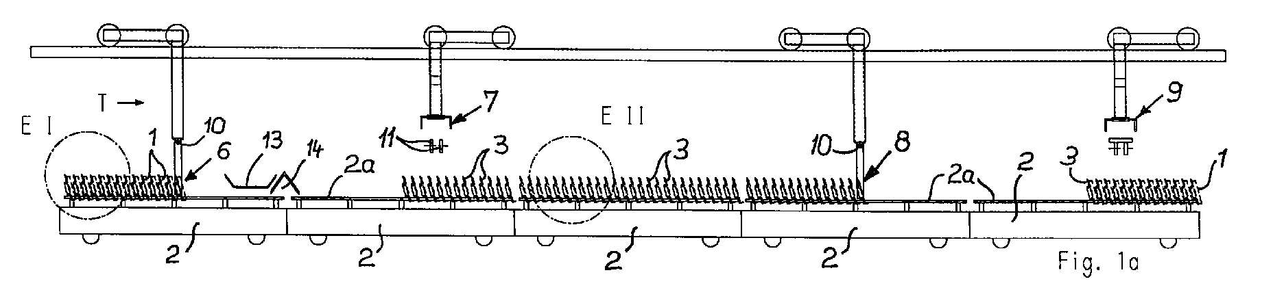
- the invention relates to a method and a system for burning Roof tile moldings 1 the area of loading and unloading and thus the Kiln furniture handling area.
- the kiln furniture is called firing rack 3 designated.
- Each firing frame 3 is composed of a support frame 4 and one Number of moldings 5 together.
- the support frames 4 extend transversely to their length Direction of transport T of tunnel kiln cars 2. You take narrow tunnel kilns the entire carriage width and, in the case of wide tunnel kilns, approximately half the carriage width on.
- the so-called support frame 4 of each firing frame 3 has as a stand trained side parts 4a, which are penetrated by cross bars 4b which the individual molded carriers 5 are arranged.
- Each firing rack 3 is designed such that the arranged thereon Roof tile moldings 1 during firing in one from the vertical inclined angle (from about 50 - 85 ° between the horizontal and the Support the back of the molded part).
- Each support frame 4 is designed such that it can be set up without locking means for a secure arrangement.
- On the Firing rack 3 is a cross row of moldings as shown in the drawing arranged - however, two rows of moldings can also be provided.
- the molding carrier 5 are designed such that there is a correct shape Rear support for the roof tile moldings (in particular interlocking tile moldings) results.
- the advantageous shaped support is i.a. each by one Support bar 5a guaranteed.
- the individual blank supports 5 can on the cross bars 4b in one Plug connection (see FIG. 5) or in a hanging arrangement (see FIG. 6) be arranged.
- the illustrated embodiments only show that Basic principle and allow many design options.
- FIG. 5 there is a slight pivoting of the firing frame possible for automatic kiln furniture cleaning (see FIG. 1c) without an additional safety measure (fall protection) is required.
- the embodiment according to FIG. 6 has the advantage that in the event of a possible Blank carrier damage such a blank carrier 5 is easily interchangeable.
- the cross bars 4b are above the outer Side surface of each side part / stand 4a over.
- the foreheads of the Crossbars 4b represent the gripping surfaces for gripping the frame.
- the supporting frame side parts 4a and supporting frame crossbars are preferably 4b tubular.
- the material is highly heat resistant and consists preferably of SiSiC - whereas the refractory molded carriers 5 preferably made of cheaper ceramic material (e.g. cordierite or the like) consist.
- Each tunnel kiln car 2 only needs stable ones for setting up the burning frame Support surfaces 2a, in particular longitudinal rails, and less in the rest of the area resilient and therefore designed to be highly heat-insulating.
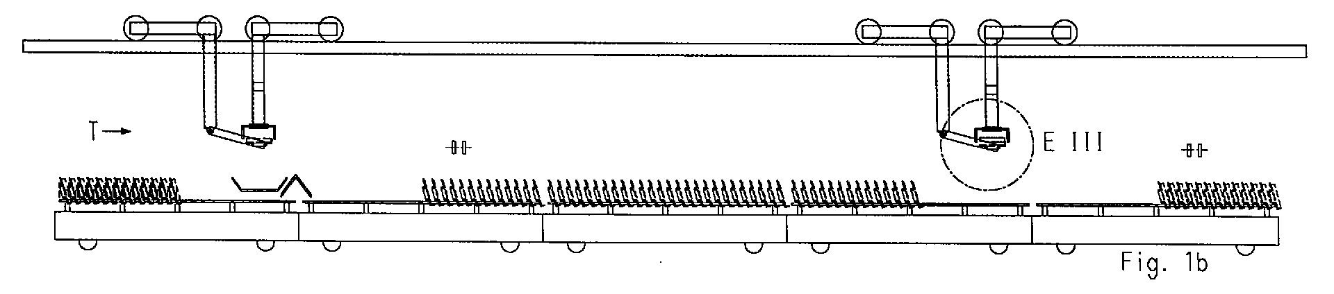
- FIGS. 1c The movement sequence of the individual phases of loading and unloading is shown in FIGS. 1c, so that a detailed description is unnecessary. It will only noted that item 6 passes to 7 and item 8 to 9. Conveyors 11 and 12 preferably run horizontally - as can be seen from the drawing (see FIGS. 1a-1c).
- the individual tunnel kiln cars 2 are moved in cycles, the so-called The car thrust is the same length as the kiln car length.
- the so-called "fine clocking" for loading and unloading the individual firing racks (firing aids) 3 is carried out by means of of the individual ones that can be moved back and forth parallel to the wagon track (not shown) Gripping devices, which are numbered 6, 7, 8 and 9 as a whole.
- the Gripping devices 6 and 8 each grasp a firing frame 3 at the ends thereof and the gripping devices 7 and 9 are for unloading roof tiles and for loading moldings intended.
- the gripping device 6 for firing frames 3 loaded with fired roof tiles 2 and for depositing empty burning frames, so-called empty cassettes
- the Gripping device 8 for unloaded / empty firing racks 3
- a movable, snap-in base frame whose swivel axis is numbered 10
- the roof tile gripping device 7 for the unloading process
- the molded article gripping device 9 for the loading process
- the crane rails for the mobility of the gripping devices 6 - 9 are 20 figured.
- the roof tiles are removed by means of a transport direction transverse to the tunnel kiln car T running conveyor 11.
- the supply of the to be burned Roof tile moldings 1 takes place by means of a transverse to the kiln car transport direction T trending conveyor 12.
- FIGS. 1a-1c Basic position "is preferably divided roughly in half between two adjacent tunnel kiln cars 2.
- a brick breakage collecting device 13, in particular a so-called break belt, is advantageously arranged within this combustion frame-free space, onto which any fragments, flaking and the like that may be present can be obtained by simply pivoting the lower area of the Support structure of the gripping device 6 about its pivot axis 10 is possible (see FIG. 1c).
- a tunnel kiln car cleaning device 14 can also be arranged in the same combustion chamber-free space - the same can be formed by a suction device or have one (for example a suction bar).
- At least the firing frame gripping device 8 is one from FIGS. 7-9 Removable adjustment device 15 assigned by means of an automatic Adjustment of a recorded firing frame 3 in the relative position to the parallel gripping jaws is possible.
- the tunnel kiln cars 2 are preferably for firing on the side of the kiln conceived and accordingly are those that form a rigid abutment and with 2a numbered longitudinal rails arranged at a distance from the car plateau surface.
Landscapes
- Engineering & Computer Science (AREA)
- Chemical & Material Sciences (AREA)
- Ceramic Engineering (AREA)
- Mechanical Engineering (AREA)
- General Engineering & Computer Science (AREA)
- Materials Engineering (AREA)
- Dispersion Chemistry (AREA)
- Structural Engineering (AREA)
- Organic Chemistry (AREA)
- Furnace Charging Or Discharging (AREA)
- Tunnel Furnaces (AREA)
- Devices For Post-Treatments, Processing, Supply, Discharge, And Other Processes (AREA)
- Furnace Housings, Linings, Walls, And Ceilings (AREA)
- Glass Compositions (AREA)
- Press-Shaping Or Shaping Using Conveyers (AREA)
Abstract

Description
- 1
- Dachziegel-Formling oder Dachziegel
- 2
- Tunnelofenwagen
- 2a
- stabile Stützflächen, insbesondere Längsschienen als Trag- und Abstellflächen für Brenngestelle 3
- 3
- Brenngestelle
- 4
- Traggestell (Bestandteil von 3)
- 4a
- Seitenteile, insbesondere Ständer
- 4b
- Querstangen
- 5
- Formlingsträger (Bestandteil von 3)
- 5a
- Stützleiste für Dachziegel-Falz oder gegenüber der Dachziegel-Hauptfläche
versetzte Kante - 6
- Greifeinrichtung für mit gebrannten Dachziegeln 2 beladene Brenngestelle
3
sowie zum Absetzen von geleerten Brenngestellen 3 (sogen. Leerkassetten) - 7
- Dachziegel-Greifeinrichtung (für den Entladevorgang)
- 8
- Greifeinrichtung für unbeladene (leere) Brenngestelle 3
- 9
- Formlings-Greifeinrichtung (für den Beladevorgang)
- 10
- Schwenkachse (innerhalb von 6 - 8)
- 11
- Förderer für die Abförderung gebrannter Dachziegel 1
- 12
- Förderer für die Zufuhr von zu brennenden Dachziegel-Formlingen 1
- 13
- Ziegelbruch-Auffangeinrichtung, insbes. sogen. Bruchband
- 14
- Tunnelofenwagen-Reinigungseinrichtung
- 15
- Justiereinrichtung für genaues Ausrichten (in Relativlage) eines Brenngestells 3 gegenüber der Greifbacken-Lage
- 20
- Kranschienen für 6 - 9
- T
- Transportrichtung
Claims (11)
- Verfahren zum Brennen von Dachziegel-Formlingen auf Ofenwagen, wobei getrocknete Dachziegel in einlagiger Anordnung, unter Abstützung an der Rückseite, einen Tunnelofen durchlaufen, dadurch gekennzeichnet, daßa) getrocknete Dachziegel (1) für einen Tunnelofen-Durchlauf in QuerreihenAnordnung außerhalb der Tunnelofenwagen-Bewegungsbahn flachliegend einer Brennhilfsmittel-Beladestation zugefördert sowie in derselben, jeweils einlagig auf ein eine Vielzahl von Dachziegel-Formlingen aufnehmendes sowie zur formgerechten Dachziegel-Einzelunterstützung ausgebildetes Brenngestell (3) - in Form eines Traggestells (4) mit daran angeordneten Formlingsträgern (5) - flachliegend aufgelegt werden,b) die formlingsbestückten Brenngestelle (3) um eine Horizontalachse geschwenkt sowie mit Abstand zueinander derart auf einen Tunnelofenwagen (2) abgesetzt werden, daß die zur Wagentransportrichtung (T) quer verlaufenden Formlingsreihen eine aus der Vertikalen geneigte Formlings-Schrägstellung aufweisen, undc) nach dem Brennen die Brenngestelle (Brennhilfsmittel) (3) vom Tunnelofenwagen (2) abgenommen und für die Dachziegel-Entladung bis zur Dachziegel-Flachlage zurückgeschwenkt sowie auf einen Zwischenspeicherungsplatz abgestellt werden.
- Verfahren nach Anspruch 1, dadurch gekennzeichnet, daß die Brenngestell-Beladung mit zu brennenden Dachziegel-Formlingen (1) und /oder die Brenngestell-Entladung von gebrannten Dachziegeln (1) oberhalb der Tunnelofenwagen (2) durchgeführt wird.
- Verfahren nach Anspruch 1, dadurch gekennzeichnet, daß die Brenngestell-Beladung mit zu brennenden Dachziegel-Formlingen (1) und/oder die Brenngestell-Entladung von gebrannten Dachziegel-Formlingen (1) neben der Durchlaufbahn der Tunnelofenwagen (2) durchgeführt wird.
- Verfahren nach einem der Ansprüche 1 bis 3, dadurch gekennzeichnet, daß die Brenngestelle (3) für Umsetzbewegungen jeweils stirnendig, d. h. an beiden Enden der Fromlingsträger-Reihe ergriffen werden.
- Verfahren nach einem der Ansprüche 1 bis 4, dadurch gekennzeichnet, daß die Brenngestelle (3) mit höhenmäßigem Abstand zur OfenwagenPlattform abgestellt und durch einen seitenbefeuerten Tunnelofen gefahren werden.
- Anlage zum Brennen von Dachziegel-Formlingen unter Zuhilfenahme von Brennhilfsmitteln, welche mit die Formlings-Rückseite formgerecht unterstützenden Stützelementen oder Stützflächen ausgebildet sind, sowie zur Durchführung des Verfahrens nach einem der Ansprüche 1 bis 5, dadurch gekennzeichnet, daß die Brennhilfsmittel von Brenngestellen (3) gebildet sind, welche jeweils ein Traggestell (Grundgestell) (4) und eine Vielzahl daran in einer horizontalen Reihe angeordneter Formlingsträger (5) aufweisen, wobei das Traggestell (4) selbststehend, d. h. arretiermittelfrei standsicher absetzbar, ausgeführt ist und zwischen zwei Seitenteilen (Ständern) (4a) querverlaufende rohrförmige Querstangen (4b) aufweist, welche die Formlingsträger (5) in der Funktionsstellung für das Dachziegel-Brennen in einer aus der vertikalen geneigten Schrägstellung aufnehmen (tragen) sowie stirnendig Greifflächen zum Greifmittel-Ansetzen aufweisen.
- Anlage zum Brennen von Dachziegel-Formlingen unter Zuhilfenahme von Brennhilfsmitteln, welche mit die Formlings-Rückseite formgerecht unterstützenden Stützelementen oder Stützflächen ausgebildet sind, sowie zur Durchführung des Verfahrens nach einem der Ansprüche, dadurch gekennzeichnet, daßa) die Brennhilfsmittel von Brenngestellen (3) mit in einem Traggestell (Grundgestell) (4) in einer horizontalen Reihe sowie jeweils in einer aus der vertikalen geneigten Schrägstellung, angeordneten Formlingsträgern (5) gebildet sind, die stirnendige Greifflächen zum Greifmittel-Ansetzen aufweisen sowie arretiermittelfrei standsicher absetzbar ausgeführt sind.b) für die Zuführung von zu brennenden Dachziegel-Formlingen (1) und / oder für die Abführung der gebrannten Dachziegel (1) horizontale Förderer (11,12) vorhanden sind, die sich außerhalb der TunnelofenBewegungsbahn, jedoch mit geringem Abstand zu derselben, erstrecken, undc) zum Brenngestell-Umsetzen Greifeinrichtungen (6, 8) mit um eine horizontale Schwenkachse (10) bewegbaren Greifköpfen, insbesondere Parallelgreifern, vorhanden sind.
- Anlage nach Anspruch 6 oder 7, dadurch gekennzeichnet, daß die Greifeinrichtungen (6, 7, 8, 9) für das Umsetzen der Brenngestelle (3) sowie der Dachziegel-Formlinge und Dachziegel (1) auf einer oberhalb der Tunnelofenwagen-Durchlaufbahn angeordneten Kranbahn verfahrbar vorgesehen sind.
- Anlage nach einem der Ansprüche 6 bis 8, dadurch gekennzeichnet, daß die Brenngestelle (3) jeweils ein Traggestell (4) mit zwei ständerbildenden Seitenteilen (4a) sowie außenseitig über diese (4a) hinausragenden Querverbindern (Pos. 4b), auf welche eine Vielzahl von heißgasdurchströmbaren Formlingsträgern (5) in Steck- und / oder Einhak-Verbindung angeordnet sind, aufweisen.
- Anlage nach einem der Ansprüche 6 bis 9, dadurch gekennzeichnet, daß die Traggestell-Seitenteile (4a) und Querverbinder aus hitzebeständigem Rohr, insbesondere aus SiSiC, bestehen.
- Anlage nach einem der Ansprüche 6 bis 10, dadurch gekennzeichnet, daß die Formlingsträger (5) in der Art eines H-Kassetten-Steges ausgebildet sind und aus einem niedrigbelastbaren Werkstoff, insbesondere auf Keramik-Basis, bestehen.
Applications Claiming Priority (4)
| Application Number | Priority Date | Filing Date | Title |
|---|---|---|---|
| DE1997118252 DE19718252A1 (de) | 1997-04-30 | 1997-04-30 | Verfahren zum Brennen von Dachziegel-Formlingen und Anlage zu dessen Durchführung |
| DE1997118253 DE19718253A1 (de) | 1997-04-30 | 1997-04-30 | Verfahren zum Brennen von Dachziegel-Formlingen und Anlage zu dessen Durchführung |
| DE19718252 | 1997-04-30 | ||
| DE19718253 | 1997-07-30 |
Publications (2)
| Publication Number | Publication Date |
|---|---|
| EP0903553A2 true EP0903553A2 (de) | 1999-03-24 |
| EP0903553A3 EP0903553A3 (de) | 1999-04-07 |
Family
ID=26036204
Family Applications (2)
| Application Number | Title | Priority Date | Filing Date |
|---|---|---|---|
| EP98107937A Withdrawn EP0903553A3 (de) | 1997-04-30 | 1998-04-30 | Verfahren und Anlage zum Brennen von Dachziegel-Formlingen |
| EP98107936A Expired - Lifetime EP0903552B1 (de) | 1997-04-30 | 1998-04-30 | Brennhilfsmittel für Dachziegel |
Family Applications After (1)
| Application Number | Title | Priority Date | Filing Date |
|---|---|---|---|
| EP98107936A Expired - Lifetime EP0903552B1 (de) | 1997-04-30 | 1998-04-30 | Brennhilfsmittel für Dachziegel |
Country Status (3)
| Country | Link |
|---|---|
| EP (2) | EP0903553A3 (de) |
| AT (1) | ATE258299T1 (de) |
| DE (1) | DE59810623D1 (de) |
Family Cites Families (6)
| Publication number | Priority date | Publication date | Assignee | Title |
|---|---|---|---|---|
| DE3244183C1 (de) * | 1982-11-30 | 1984-05-24 | C. Keller GmbH u. Co KG, 4530 Ibbenbüren | Anlage zur kontinuierlichen Herstellung von gebrannten, plattenförmigen keramischen Formlingen, insbesondere Dachziegeln |
| DE3340282A1 (de) * | 1983-11-08 | 1985-05-23 | Johannes Arno Hartenstein Kg, 8670 Hof | Greifvorrichtung |
| DE3425625A1 (de) * | 1984-07-12 | 1986-01-16 | Andreas Ing.(grad.) 7904 Erbach Häßler | Verfahren und vorrichtung zum transportieren und trocknen von tondachziegeln |
| DE4337189C2 (de) * | 1993-10-30 | 1995-11-09 | Pm Hochtemperatur Metall Gmbh | Chargiergestell für das Brennen von Gegenständen aus keramischen und glaskeramischen Werkstoffen |
| DE29518345U1 (de) * | 1995-11-18 | 1996-01-11 | Burton-Werke K.-F. Hensiek GmbH + Co. KG, 49328 Melle | Brennkassette für Ortgangziegel |
| EP0786636A1 (de) * | 1996-01-26 | 1997-07-30 | Keller GmbH | Verfahren und Ofenwagen zum Brennen von Falzdachziegeln |
-
1998
- 1998-04-30 EP EP98107937A patent/EP0903553A3/de not_active Withdrawn
- 1998-04-30 EP EP98107936A patent/EP0903552B1/de not_active Expired - Lifetime
- 1998-04-30 DE DE59810623T patent/DE59810623D1/de not_active Expired - Fee Related
- 1998-04-30 AT AT98107936T patent/ATE258299T1/de not_active IP Right Cessation
Also Published As
| Publication number | Publication date |
|---|---|
| ATE258299T1 (de) | 2004-02-15 |
| EP0903552B1 (de) | 2004-01-21 |
| EP0903552A2 (de) | 1999-03-24 |
| EP0903552A3 (de) | 1999-04-07 |
| DE59810623D1 (de) | 2004-02-26 |
| EP0903553A3 (de) | 1999-04-07 |
Similar Documents
| Publication | Publication Date | Title |
|---|---|---|
| DE2733016C2 (de) | Vorrichtung zum Füllen und Entleeren sowie zum gleichzeitigen Stapeln und Entstapeln von Kapseln für keramisches Gut | |
| DE3244183C1 (de) | Anlage zur kontinuierlichen Herstellung von gebrannten, plattenförmigen keramischen Formlingen, insbesondere Dachziegeln | |
| EP0786636A1 (de) | Verfahren und Ofenwagen zum Brennen von Falzdachziegeln | |
| DE2030602A1 (de) | Verfahren und Vorrichtung zur Be handlung von Ziegelformhngen vom Strang abschneider bis auf Brennofenwagen | |
| EP0903553A2 (de) | Verfahren und Anlage zum Brennen von Dachziegel-Formlingen | |
| DE3442161A1 (de) | Einrichtung zum umladen von auf unterlagen angeordneten keramischen formlingen | |
| CH409756A (de) | Steinstapel und Verfahren zum Erstellen desselben und Setzmaschine zur Ausübung des Verfahrens | |
| DE1901851B2 (de) | Einrichtung fuer den transport von vorbrammen in walzwerken | |
| DE19718253A1 (de) | Verfahren zum Brennen von Dachziegel-Formlingen und Anlage zu dessen Durchführung | |
| DE29807793U1 (de) | Brennhilfsmittel für Dachziegel | |
| DE3128655A1 (de) | "ofen fuer die waermebehandlung von glasscheiben" | |
| DE19609474C1 (de) | Verfahren und Anlage zur Herstellung von Dachziegeln | |
| DE19639985A1 (de) | Verfahren und Vorrichtung sowie Anlage zum Herstellen von Kalksandsteinen | |
| AT405878B (de) | Verfahren zum trocknen von formlingen aus keramischem material, insbesondere von ziegeln, sowie anlage zur durchführung des verfahrens | |
| EP1136779B1 (de) | Wagen zum Transport von Keramikrohlingen | |
| EP0662597B1 (de) | Verfahren zum vollautomatischen Beladen eines mehrlagigen Gestellaufbaus von Ofenwagen zum Brennen von Keramikteilen und Vorrichtung zur Verfahrensdurchführung | |
| DE19729556C1 (de) | Anlage zur Herstellung von Keramikprodukten | |
| DE29802631U1 (de) | Anlage zur Herstellung von Dachziegeln | |
| DE19934122A1 (de) | Brennanlage für keramische Produkte, insbesondere Ziegel, mit einem im Gegenlauf betriebenen Tunnelofen | |
| DE4200012C2 (de) | Verfahren zum Brennen von Dach-Falzziegeln | |
| DE3248234A1 (de) | Verfahren zum transport von dachziegeln in einem tunnelofen | |
| DE19937870C1 (de) | Verfahren zum Dachziegel-Brennen sowie Schrägbesatz-Kassetten zur Durchführung desselben | |
| DE19744966C2 (de) | Dachziegel-Greifvorrichtung | |
| DE19702871C2 (de) | Anlage zum Trocknen und Brennen keramischer Formlinge, insbesondere Mauer- oder Dachziegel | |
| DE19725162A1 (de) | Verfahren und Vorrichtung zum Brennen von keramischen Rohren |
Legal Events
| Date | Code | Title | Description |
|---|---|---|---|
| PUAI | Public reference made under article 153(3) epc to a published international application that has entered the european phase |
Free format text: ORIGINAL CODE: 0009012 |
|
| PUAL | Search report despatched |
Free format text: ORIGINAL CODE: 0009013 |
|
| AK | Designated contracting states |
Kind code of ref document: A2 Designated state(s): AT BE CH CY DE DK ES FI FR GB GR IE IT LI LU MC NL PT SE |
|
| AX | Request for extension of the european patent |
Free format text: AL;LT;LV;MK;RO;SI |
|
| AK | Designated contracting states |
Kind code of ref document: A3 Designated state(s): AT BE CH CY DE DK ES FI FR GB GR IE IT LI LU MC NL PT SE |
|
| AX | Request for extension of the european patent |
Free format text: AL;LT;LV;MK;RO;SI |
|
| RIN1 | Information on inventor provided before grant (corrected) |
Inventor name: DERHAKE, THOMAS PROF. DR.-ING. |
|
| AKX | Designation fees paid | ||
| STAA | Information on the status of an ep patent application or granted ep patent |
Free format text: STATUS: THE APPLICATION IS DEEMED TO BE WITHDRAWN |
|
| 18D | Application deemed to be withdrawn |
Effective date: 19991008 |
|
| REG | Reference to a national code |
Ref country code: DE Ref legal event code: 8566 |