EP0903552A2 - Accessoire d'enfournement pour tuiles de toiture - Google Patents
Accessoire d'enfournement pour tuiles de toiture Download PDFInfo
- Publication number
- EP0903552A2 EP0903552A2 EP98107936A EP98107936A EP0903552A2 EP 0903552 A2 EP0903552 A2 EP 0903552A2 EP 98107936 A EP98107936 A EP 98107936A EP 98107936 A EP98107936 A EP 98107936A EP 0903552 A2 EP0903552 A2 EP 0903552A2
- Authority
- EP
- European Patent Office
- Prior art keywords
- roof tile
- firing
- frame
- frame according
- support
- Prior art date
- Legal status (The legal status is an assumption and is not a legal conclusion. Google has not performed a legal analysis and makes no representation as to the accuracy of the status listed.)
- Granted
Links
Images


Classifications
-
- C—CHEMISTRY; METALLURGY
- C04—CEMENTS; CONCRETE; ARTIFICIAL STONE; CERAMICS; REFRACTORIES
- C04B—LIME, MAGNESIA; SLAG; CEMENTS; COMPOSITIONS THEREOF, e.g. MORTARS, CONCRETE OR LIKE BUILDING MATERIALS; ARTIFICIAL STONE; CERAMICS; REFRACTORIES; TREATMENT OF NATURAL STONE
- C04B33/00—Clay-wares
- C04B33/32—Burning methods
-
- F—MECHANICAL ENGINEERING; LIGHTING; HEATING; WEAPONS; BLASTING
- F27—FURNACES; KILNS; OVENS; RETORTS
- F27D—DETAILS OR ACCESSORIES OF FURNACES, KILNS, OVENS OR RETORTS, IN SO FAR AS THEY ARE OF KINDS OCCURRING IN MORE THAN ONE KIND OF FURNACE
- F27D3/00—Charging; Discharging; Manipulation of charge
- F27D3/0021—Charging; Discharging; Manipulation of charge of ceramic ware
-
- F—MECHANICAL ENGINEERING; LIGHTING; HEATING; WEAPONS; BLASTING
- F27—FURNACES; KILNS; OVENS; RETORTS
- F27D—DETAILS OR ACCESSORIES OF FURNACES, KILNS, OVENS OR RETORTS, IN SO FAR AS THEY ARE OF KINDS OCCURRING IN MORE THAN ONE KIND OF FURNACE
- F27D5/00—Supports, screens or the like for the charge within the furnace
- F27D5/005—Supports specially adapted for holding elongated articles in an upright position, e.g. sparking plugs
Definitions
- the invention relates to a kiln furniture for burning roof tiles in single layer arrangement.
- the invention has for its object an improved fuel for single-layer burning of roof tiles to create a form-fitting Shaped support as with H-cassette systems enables, however Avoids disadvantages of H-cassettes.
- each firing frame has a large width - up to about 3.5 m with currently commercially available ones Profiles or pipes made of SiSiC - it can be used in a tunnel furnace entire carriage width or (in the case of a particularly wide oven format) half Take up the carriage width and yet there are only two longitudinal support strips required on the top of the carriage, which is a particularly simple and highly effective car insulation enables.
- the Burning rack concept according to the invention only the support frame (side parts / stand plus Ouer connector) made of expensive material, especially non-oxide ceramics (e.g. SiC or SiSiC), and the shaped carriers, which function as the H-web of an H-cassette take over, from cheaper material, especially silicate ceramics (e.g. cordierite, mullite or the like) can be produced - this results in a reduction of investment costs.
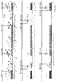
- the invention relates to the area in a system for firing roof tile moldings 1 Kiln furniture ".
- the kiln furniture is referred to as the firing frame 3.
- Each firing frame 3 is composed of a support frame 4 and a number of molded carriers 5.
- the support frames 4 extend transversely to their length Direction of transport T of tunnel kiln cars 2. You take narrow tunnel kilns the entire carriage width and, in the case of wide tunnel kilns, approximately half the carriage width on.
- the so-called support frame 4 of each firing frame 3 has as a stand trained side parts 4a, which are penetrated by cross bars 4b which the individual molded carriers 5 are arranged.
- Each firing rack 3 is designed such that the arranged thereon Roof tile moldings 1 during firing in one from the vertical inclined angle (from about 50 - 85 ° between the horizontal and the Support the back of the molded part).
- Each support frame 4 is designed such that it can be set up without locking means for a secure arrangement.
- On the Firing rack 3 is a cross row of moldings as shown in the drawing arranged - however, two rows of moldings can also be provided.
- the molding carrier 5 are designed such that there is a correct shape Rear support for the roof tile moldings (in particular interlocking tile moldings) results.
- the advantageous shaped support is i.a. each by one Support bar 5a guaranteed.
- the individual blank supports 5 can on the cross bars 4b in one Plug connection (see FIG. 5) or in a hanging arrangement (see FIG. 6) be arranged.
- the illustrated embodiments only show that Basic principle and allow many design options.
- FIG. 5 there is a slight pivoting of the firing frame possible for automatic kiln furniture cleaning (see FIG. 1c) without an additional safety measure (fall protection) is required.
- the embodiment according to FIG. 6 has the advantage that in the event of a possible Blank carrier damage such a blank carrier 5 is easily interchangeable.
- the cross bars 4b are above the outer Side surface of each side part / stand 4a over.
- the foreheads of the Crossbars 4b represent the gripping surfaces for gripping the frame.
- the support frame side parts 4a and support frame crossbars are preferred 4b tubular.
- the material is highly heat resistant and consists preferably of SiSiC - whereas the refractory molded carriers 5 preferably made of cheaper ceramic material (e.g. cordierite or the like) consist.
- Each tunnel kiln car 2 only needs stable ones for setting up the burning frame Support surfaces 2a, in particular longitudinal rails, and less in the rest of the area resilient and therefore designed to be highly heat-insulating.
- the individual tunnel kiln cars 2 are moved in cycles, the so-called The car thrust is the same length as the kiln car length.
- the so-called "Fine clocking" for loading and unloading the individual burners (Kiln furniture) 3 is done by means of the individual, parallel to the wagon track (not shown) back and forth gripping devices, each as a whole with 6, 7, 8 and 9 are numbered.
- the gripping devices 6 and 8 each grasp one Firing frame 3 at its ends and the gripping devices 7 and 9 are for the Unloading of roof tiles or loading for shaped articles.
- the gripping device 6 for firing frames 3 loaded with fired roof tiles 2 as well as for placing empty burning frames, so-called empty cassettes
- the gripping device 8 for unloaded / empty firing racks 3
- a movable, foldable base frame whose swivel axis is numbered 10
- the roof tile gripping device 7 for the unloading process
- the blank gripping device 9 for the loading process
- the crane rails for the mobility of the Gripping devices 6 - 9 are numbered 20.
- the roof tiles are removed by means of a transport direction transverse to the tunnel kiln car T running conveyor 11.
- the supply of the to be burned Roof tile moldings 1 is carried out by means of a transverse to the kiln car transport direction T running conveyor 12.
- FIGS. 1a-1c Basic position "is preferably divided roughly in half between two adjacent tunnel kiln cars 2.
- a brick breakage collecting device 13, in particular a so-called break belt, is advantageously arranged within this combustion frame-free space, onto which any fragments, flaking and the like that may be present can be obtained by simply pivoting the lower area of the Supporting structure of the
- Gripping device 6 about its pivot axis 10 is possible (see FIG. 1c).
- a tunnel kiln car cleaning device can also be used in the area free of the burning rack 14 can be arranged - the same can be from one Suction device can be formed or have one (e.g. a suction bar).
- the tunnel kiln cars 2 are preferably for firing on the side of the kiln conceived and accordingly are those that form a rigid abutment and with 2a numbered longitudinal rails arranged at a distance from the car plateau surface.
Landscapes
- Engineering & Computer Science (AREA)
- Chemical & Material Sciences (AREA)
- Ceramic Engineering (AREA)
- Mechanical Engineering (AREA)
- General Engineering & Computer Science (AREA)
- Materials Engineering (AREA)
- Dispersion Chemistry (AREA)
- Structural Engineering (AREA)
- Organic Chemistry (AREA)
- Furnace Charging Or Discharging (AREA)
- Tunnel Furnaces (AREA)
- Devices For Post-Treatments, Processing, Supply, Discharge, And Other Processes (AREA)
- Furnace Housings, Linings, Walls, And Ceilings (AREA)
- Glass Compositions (AREA)
- Press-Shaping Or Shaping Using Conveyers (AREA)
Applications Claiming Priority (4)
| Application Number | Priority Date | Filing Date | Title |
|---|---|---|---|
| DE1997118252 DE19718252A1 (de) | 1997-04-30 | 1997-04-30 | Verfahren zum Brennen von Dachziegel-Formlingen und Anlage zu dessen Durchführung |
| DE1997118253 DE19718253A1 (de) | 1997-04-30 | 1997-04-30 | Verfahren zum Brennen von Dachziegel-Formlingen und Anlage zu dessen Durchführung |
| DE19718252 | 1997-04-30 | ||
| DE19718253 | 1997-07-30 |
Publications (3)
| Publication Number | Publication Date |
|---|---|
| EP0903552A2 true EP0903552A2 (fr) | 1999-03-24 |
| EP0903552A3 EP0903552A3 (fr) | 1999-04-07 |
| EP0903552B1 EP0903552B1 (fr) | 2004-01-21 |
Family
ID=26036204
Family Applications (2)
| Application Number | Title | Priority Date | Filing Date |
|---|---|---|---|
| EP98107937A Withdrawn EP0903553A3 (fr) | 1997-04-30 | 1998-04-30 | Procédé et installation pour la cuisson de tuiles de toiture |
| EP98107936A Expired - Lifetime EP0903552B1 (fr) | 1997-04-30 | 1998-04-30 | Accessoire d'enfournement pour tuiles de toiture |
Family Applications Before (1)
| Application Number | Title | Priority Date | Filing Date |
|---|---|---|---|
| EP98107937A Withdrawn EP0903553A3 (fr) | 1997-04-30 | 1998-04-30 | Procédé et installation pour la cuisson de tuiles de toiture |
Country Status (3)
| Country | Link |
|---|---|
| EP (2) | EP0903553A3 (fr) |
| AT (1) | ATE258299T1 (fr) |
| DE (1) | DE59810623D1 (fr) |
Family Cites Families (6)
| Publication number | Priority date | Publication date | Assignee | Title |
|---|---|---|---|---|
| DE3244183C1 (de) * | 1982-11-30 | 1984-05-24 | C. Keller GmbH u. Co KG, 4530 Ibbenbüren | Anlage zur kontinuierlichen Herstellung von gebrannten, plattenförmigen keramischen Formlingen, insbesondere Dachziegeln |
| DE3340282A1 (de) * | 1983-11-08 | 1985-05-23 | Johannes Arno Hartenstein Kg, 8670 Hof | Greifvorrichtung |
| DE3425625A1 (de) * | 1984-07-12 | 1986-01-16 | Andreas Ing.(grad.) 7904 Erbach Häßler | Verfahren und vorrichtung zum transportieren und trocknen von tondachziegeln |
| DE4337189C2 (de) * | 1993-10-30 | 1995-11-09 | Pm Hochtemperatur Metall Gmbh | Chargiergestell für das Brennen von Gegenständen aus keramischen und glaskeramischen Werkstoffen |
| DE29518345U1 (de) * | 1995-11-18 | 1996-01-11 | Burton-Werke K.-F. Hensiek GmbH + Co. KG, 49328 Melle | Brennkassette für Ortgangziegel |
| EP0786636A1 (fr) * | 1996-01-26 | 1997-07-30 | Keller GmbH | Procédé et voiture pour cuire des tuiles à emboîtement |
-
1998
- 1998-04-30 EP EP98107937A patent/EP0903553A3/fr not_active Withdrawn
- 1998-04-30 EP EP98107936A patent/EP0903552B1/fr not_active Expired - Lifetime
- 1998-04-30 DE DE59810623T patent/DE59810623D1/de not_active Expired - Fee Related
- 1998-04-30 AT AT98107936T patent/ATE258299T1/de not_active IP Right Cessation
Also Published As
| Publication number | Publication date |
|---|---|
| ATE258299T1 (de) | 2004-02-15 |
| EP0903553A2 (fr) | 1999-03-24 |
| EP0903552B1 (fr) | 2004-01-21 |
| EP0903552A3 (fr) | 1999-04-07 |
| DE59810623D1 (de) | 2004-02-26 |
| EP0903553A3 (fr) | 1999-04-07 |
Similar Documents
| Publication | Publication Date | Title |
|---|---|---|
| EP2568244B1 (fr) | Procédé et appareil de cuisson d'ébauches en céramique et four | |
| EP3355015B1 (fr) | Élément de support pour un chariot ou une plaque coulissante de four tunnel, chariot ou plaque coulissante de four tunnel dotés des tels éléments de support ainsi que four tunnel doté d'un tel chariot ou d'une telle plaque coulissante de four tunnel | |
| DE3519612A1 (de) | Einrichtung zum brennen von keramischen formteilen, insbesondere porzellangeschirrteilen | |
| DE112004001765T5 (de) | System und Verfahren zum Brennen von Ziegeln | |
| EP0786636A1 (fr) | Procédé et voiture pour cuire des tuiles à emboîtement | |
| EP0903552B1 (fr) | Accessoire d'enfournement pour tuiles de toiture | |
| DE29807793U1 (de) | Brennhilfsmittel für Dachziegel | |
| DE19718253A1 (de) | Verfahren zum Brennen von Dachziegel-Formlingen und Anlage zu dessen Durchführung | |
| DE3248234C2 (de) | Tunnelofen | |
| DE2846818A1 (de) | Verfahren zur waermebehandlung von kalten stahlbloecken und/oder heissen stahlbloecken sowie vorrichtung zur durchfuehrung des verfahrens | |
| DE19609474C1 (de) | Verfahren und Anlage zur Herstellung von Dachziegeln | |
| EP1136779B1 (fr) | Chariot pour le transport d'articles céramiques | |
| DE19516205C2 (de) | Anlage zum Trocknen und Brennen von keramischen Formlingen | |
| EP0330866A1 (fr) | Superstructure pour chariots de four de cuisson | |
| AT405878B (de) | Verfahren zum trocknen von formlingen aus keramischem material, insbesondere von ziegeln, sowie anlage zur durchführung des verfahrens | |
| DE202009010938U1 (de) | Verbesserter Werkstückträger | |
| DE4200012C2 (de) | Verfahren zum Brennen von Dach-Falzziegeln | |
| DE10041132A1 (de) | Tunnelofenanlage zum Brennen von keramischen Formlingen, insbesondere Ziegeln | |
| DE29802631U1 (de) | Anlage zur Herstellung von Dachziegeln | |
| DE19729556C1 (de) | Anlage zur Herstellung von Keramikprodukten | |
| DE19725162A1 (de) | Verfahren und Vorrichtung zum Brennen von keramischen Rohren | |
| DE19702871C2 (de) | Anlage zum Trocknen und Brennen keramischer Formlinge, insbesondere Mauer- oder Dachziegel | |
| DE29723936U1 (de) | Tunnelofen-Anlage zum Brennen von keramischen Produkten | |
| DE19934122A1 (de) | Brennanlage für keramische Produkte, insbesondere Ziegel, mit einem im Gegenlauf betriebenen Tunnelofen | |
| EP0519212B1 (fr) | Tuiles et procédé pour leur fabrication |
Legal Events
| Date | Code | Title | Description |
|---|---|---|---|
| PUAI | Public reference made under article 153(3) epc to a published international application that has entered the european phase |
Free format text: ORIGINAL CODE: 0009012 |
|
| PUAL | Search report despatched |
Free format text: ORIGINAL CODE: 0009013 |
|
| AK | Designated contracting states |
Kind code of ref document: A2 Designated state(s): AT CH DE DK ES FR GB LI |
|
| AX | Request for extension of the european patent |
Free format text: AL;LT;LV;MK;RO;SI |
|
| AK | Designated contracting states |
Kind code of ref document: A3 Designated state(s): AT BE CH CY DE DK ES FI FR GB GR IE IT LI LU MC NL PT SE |
|
| AX | Request for extension of the european patent |
Free format text: AL;LT;LV;MK;RO;SI |
|
| 17P | Request for examination filed |
Effective date: 19991005 |
|
| AKX | Designation fees paid |
Free format text: AT BE CH DE FR GB LI NL |
|
| RAP1 | Party data changed (applicant data changed or rights of an application transferred) |
Owner name: KELLER H.C.W. GMBH |
|
| RAP1 | Party data changed (applicant data changed or rights of an application transferred) |
Owner name: KELLER GMBH |
|
| 19U | Interruption of proceedings before grant |
Effective date: 20001201 |
|
| 19W | Proceedings resumed before grant after interruption of proceedings |
Effective date: 20020625 |
|
| RBV | Designated contracting states (corrected) |
Designated state(s): AT CH DE DK ES FR GB LI |
|
| GRAH | Despatch of communication of intention to grant a patent |
Free format text: ORIGINAL CODE: EPIDOS IGRA |
|
| RAP1 | Party data changed (applicant data changed or rights of an application transferred) |
Owner name: KELLER H.C.W. GMBH |
|
| 18D | Application deemed to be withdrawn |
Effective date: 20021204 |
|
| GRAS | Grant fee paid |
Free format text: ORIGINAL CODE: EPIDOSNIGR3 |
|
| GRAA | (expected) grant |
Free format text: ORIGINAL CODE: 0009210 |
|
| D18D | Application deemed to be withdrawn (deleted) | ||
| AK | Designated contracting states |
Kind code of ref document: B1 Designated state(s): AT CH DE DK ES FR GB LI |
|
| PG25 | Lapsed in a contracting state [announced via postgrant information from national office to epo] |
Ref country code: GB Free format text: LAPSE BECAUSE OF FAILURE TO SUBMIT A TRANSLATION OF THE DESCRIPTION OR TO PAY THE FEE WITHIN THE PRESCRIBED TIME-LIMIT Effective date: 20040121 Ref country code: FR Free format text: LAPSE BECAUSE OF FAILURE TO SUBMIT A TRANSLATION OF THE DESCRIPTION OR TO PAY THE FEE WITHIN THE PRESCRIBED TIME-LIMIT Effective date: 20040121 |
|
| REG | Reference to a national code |
Ref country code: CH Ref legal event code: EP |
|
| REF | Corresponds to: |
Ref document number: 59810623 Country of ref document: DE Date of ref document: 20040226 Kind code of ref document: P |
|
| PG25 | Lapsed in a contracting state [announced via postgrant information from national office to epo] |
Ref country code: DK Free format text: LAPSE BECAUSE OF FAILURE TO SUBMIT A TRANSLATION OF THE DESCRIPTION OR TO PAY THE FEE WITHIN THE PRESCRIBED TIME-LIMIT Effective date: 20040421 |
|
| PG25 | Lapsed in a contracting state [announced via postgrant information from national office to epo] |
Ref country code: LI Free format text: LAPSE BECAUSE OF NON-PAYMENT OF DUE FEES Effective date: 20040430 Ref country code: CH Free format text: LAPSE BECAUSE OF NON-PAYMENT OF DUE FEES Effective date: 20040430 Ref country code: AT Free format text: LAPSE BECAUSE OF NON-PAYMENT OF DUE FEES Effective date: 20040430 |
|
| PG25 | Lapsed in a contracting state [announced via postgrant information from national office to epo] |
Ref country code: ES Free format text: LAPSE BECAUSE OF FAILURE TO SUBMIT A TRANSLATION OF THE DESCRIPTION OR TO PAY THE FEE WITHIN THE PRESCRIBED TIME-LIMIT Effective date: 20040502 |
|
| GBV | Gb: ep patent (uk) treated as always having been void in accordance with gb section 77(7)/1977 [no translation filed] |
Effective date: 20040121 |
|
| PG25 | Lapsed in a contracting state [announced via postgrant information from national office to epo] |
Ref country code: DE Free format text: LAPSE BECAUSE OF NON-PAYMENT OF DUE FEES Effective date: 20041103 |
|
| PLBE | No opposition filed within time limit |
Free format text: ORIGINAL CODE: 0009261 |
|
| STAA | Information on the status of an ep patent application or granted ep patent |
Free format text: STATUS: NO OPPOSITION FILED WITHIN TIME LIMIT |
|
| REG | Reference to a national code |
Ref country code: CH Ref legal event code: PL |
|
| 26N | No opposition filed |
Effective date: 20041022 |
|
| EN | Fr: translation not filed | ||
| EN | Fr: translation not filed | ||
| REG | Reference to a national code |
Ref country code: FR Ref legal event code: ERR Free format text: BOPI DE PUBLICATION N: 05/03 PAGES: 237 PARTIE DU BULLETIN CONCERNEE: BREVETS EUROPEENS DONT LA TRADUCTION N'A PAS ETE REMISE A I'INPI IL Y A LIEU DE SUPPRIMER: LA MENTION DE LA NON REMISE. |