EP0903552A2 - Kiln furniture for roofing tiles - Google Patents
Kiln furniture for roofing tiles Download PDFInfo
- Publication number
- EP0903552A2 EP0903552A2 EP98107936A EP98107936A EP0903552A2 EP 0903552 A2 EP0903552 A2 EP 0903552A2 EP 98107936 A EP98107936 A EP 98107936A EP 98107936 A EP98107936 A EP 98107936A EP 0903552 A2 EP0903552 A2 EP 0903552A2
- Authority
- EP
- European Patent Office
- Prior art keywords
- roof tile
- firing
- frame
- frame according
- support
- Prior art date
- Legal status (The legal status is an assumption and is not a legal conclusion. Google has not performed a legal analysis and makes no representation as to the accuracy of the status listed.)
- Granted
Links
Images


Classifications
-
- C—CHEMISTRY; METALLURGY
- C04—CEMENTS; CONCRETE; ARTIFICIAL STONE; CERAMICS; REFRACTORIES
- C04B—LIME, MAGNESIA; SLAG; CEMENTS; COMPOSITIONS THEREOF, e.g. MORTARS, CONCRETE OR LIKE BUILDING MATERIALS; ARTIFICIAL STONE; CERAMICS; REFRACTORIES; TREATMENT OF NATURAL STONE
- C04B33/00—Clay-wares
- C04B33/32—Burning methods
-
- F—MECHANICAL ENGINEERING; LIGHTING; HEATING; WEAPONS; BLASTING
- F27—FURNACES; KILNS; OVENS; RETORTS
- F27D—DETAILS OR ACCESSORIES OF FURNACES, KILNS, OVENS OR RETORTS, IN SO FAR AS THEY ARE OF KINDS OCCURRING IN MORE THAN ONE KIND OF FURNACE
- F27D3/00—Charging; Discharging; Manipulation of charge
- F27D3/0021—Charging; Discharging; Manipulation of charge of ceramic ware
-
- F—MECHANICAL ENGINEERING; LIGHTING; HEATING; WEAPONS; BLASTING
- F27—FURNACES; KILNS; OVENS; RETORTS
- F27D—DETAILS OR ACCESSORIES OF FURNACES, KILNS, OVENS OR RETORTS, IN SO FAR AS THEY ARE OF KINDS OCCURRING IN MORE THAN ONE KIND OF FURNACE
- F27D5/00—Supports, screens or the like for the charge within the furnace
- F27D5/005—Supports specially adapted for holding elongated articles in an upright position, e.g. sparking plugs
Definitions
- the invention relates to a kiln furniture for burning roof tiles in single layer arrangement.
- the invention has for its object an improved fuel for single-layer burning of roof tiles to create a form-fitting Shaped support as with H-cassette systems enables, however Avoids disadvantages of H-cassettes.
- each firing frame has a large width - up to about 3.5 m with currently commercially available ones Profiles or pipes made of SiSiC - it can be used in a tunnel furnace entire carriage width or (in the case of a particularly wide oven format) half Take up the carriage width and yet there are only two longitudinal support strips required on the top of the carriage, which is a particularly simple and highly effective car insulation enables.
- the Burning rack concept according to the invention only the support frame (side parts / stand plus Ouer connector) made of expensive material, especially non-oxide ceramics (e.g. SiC or SiSiC), and the shaped carriers, which function as the H-web of an H-cassette take over, from cheaper material, especially silicate ceramics (e.g. cordierite, mullite or the like) can be produced - this results in a reduction of investment costs.
- the invention relates to the area in a system for firing roof tile moldings 1 Kiln furniture ".
- the kiln furniture is referred to as the firing frame 3.
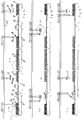
- Each firing frame 3 is composed of a support frame 4 and a number of molded carriers 5.
- the support frames 4 extend transversely to their length Direction of transport T of tunnel kiln cars 2. You take narrow tunnel kilns the entire carriage width and, in the case of wide tunnel kilns, approximately half the carriage width on.
- the so-called support frame 4 of each firing frame 3 has as a stand trained side parts 4a, which are penetrated by cross bars 4b which the individual molded carriers 5 are arranged.
- Each firing rack 3 is designed such that the arranged thereon Roof tile moldings 1 during firing in one from the vertical inclined angle (from about 50 - 85 ° between the horizontal and the Support the back of the molded part).
- Each support frame 4 is designed such that it can be set up without locking means for a secure arrangement.
- On the Firing rack 3 is a cross row of moldings as shown in the drawing arranged - however, two rows of moldings can also be provided.
- the molding carrier 5 are designed such that there is a correct shape Rear support for the roof tile moldings (in particular interlocking tile moldings) results.
- the advantageous shaped support is i.a. each by one Support bar 5a guaranteed.
- the individual blank supports 5 can on the cross bars 4b in one Plug connection (see FIG. 5) or in a hanging arrangement (see FIG. 6) be arranged.
- the illustrated embodiments only show that Basic principle and allow many design options.
- FIG. 5 there is a slight pivoting of the firing frame possible for automatic kiln furniture cleaning (see FIG. 1c) without an additional safety measure (fall protection) is required.
- the embodiment according to FIG. 6 has the advantage that in the event of a possible Blank carrier damage such a blank carrier 5 is easily interchangeable.
- the cross bars 4b are above the outer Side surface of each side part / stand 4a over.
- the foreheads of the Crossbars 4b represent the gripping surfaces for gripping the frame.
- the support frame side parts 4a and support frame crossbars are preferred 4b tubular.
- the material is highly heat resistant and consists preferably of SiSiC - whereas the refractory molded carriers 5 preferably made of cheaper ceramic material (e.g. cordierite or the like) consist.
- Each tunnel kiln car 2 only needs stable ones for setting up the burning frame Support surfaces 2a, in particular longitudinal rails, and less in the rest of the area resilient and therefore designed to be highly heat-insulating.
- the individual tunnel kiln cars 2 are moved in cycles, the so-called The car thrust is the same length as the kiln car length.
- the so-called "Fine clocking" for loading and unloading the individual burners (Kiln furniture) 3 is done by means of the individual, parallel to the wagon track (not shown) back and forth gripping devices, each as a whole with 6, 7, 8 and 9 are numbered.
- the gripping devices 6 and 8 each grasp one Firing frame 3 at its ends and the gripping devices 7 and 9 are for the Unloading of roof tiles or loading for shaped articles.
- the gripping device 6 for firing frames 3 loaded with fired roof tiles 2 as well as for placing empty burning frames, so-called empty cassettes
- the gripping device 8 for unloaded / empty firing racks 3
- a movable, foldable base frame whose swivel axis is numbered 10
- the roof tile gripping device 7 for the unloading process
- the blank gripping device 9 for the loading process
- the crane rails for the mobility of the Gripping devices 6 - 9 are numbered 20.
- the roof tiles are removed by means of a transport direction transverse to the tunnel kiln car T running conveyor 11.
- the supply of the to be burned Roof tile moldings 1 is carried out by means of a transverse to the kiln car transport direction T running conveyor 12.
- FIGS. 1a-1c Basic position "is preferably divided roughly in half between two adjacent tunnel kiln cars 2.
- a brick breakage collecting device 13, in particular a so-called break belt, is advantageously arranged within this combustion frame-free space, onto which any fragments, flaking and the like that may be present can be obtained by simply pivoting the lower area of the Supporting structure of the
- Gripping device 6 about its pivot axis 10 is possible (see FIG. 1c).
- a tunnel kiln car cleaning device can also be used in the area free of the burning rack 14 can be arranged - the same can be from one Suction device can be formed or have one (e.g. a suction bar).
- the tunnel kiln cars 2 are preferably for firing on the side of the kiln conceived and accordingly are those that form a rigid abutment and with 2a numbered longitudinal rails arranged at a distance from the car plateau surface.
Landscapes
- Engineering & Computer Science (AREA)
- Chemical & Material Sciences (AREA)
- Ceramic Engineering (AREA)
- Mechanical Engineering (AREA)
- General Engineering & Computer Science (AREA)
- Materials Engineering (AREA)
- Dispersion Chemistry (AREA)
- Structural Engineering (AREA)
- Organic Chemistry (AREA)
- Furnace Charging Or Discharging (AREA)
- Tunnel Furnaces (AREA)
- Devices For Post-Treatments, Processing, Supply, Discharge, And Other Processes (AREA)
- Furnace Housings, Linings, Walls, And Ceilings (AREA)
- Glass Compositions (AREA)
- Press-Shaping Or Shaping Using Conveyers (AREA)
Abstract
Die Erfindung betrifft ein heißluftdurchströmbares Brennhilfsmittel zum Brennen von Dachziegeln, insbesondere Falzziegeln, mit einer eine formgerechte Rückseiten-Abstützung der Dachziegel-Formlinge ermöglichenden Formlingsträger-Ausbildung. Das Erfindungswesentliche besteht darin, daß a) dasselbe als ein Brenngestell (3) zur Aufnahme einer Vielzahl von Dachziegel-Formlingen (1) in horizontaler Reihe und aus der Vertikalen geneigter Schräglage ausgebildet ist, b) es ein Traggestell (Grundgestell) (4) und eine Vielzahl von jeweils nur einen Dachziegel-Formling (1) aufnehmenden Formlingsträger (5) aufweist sowie, c) das Traggestell (4) selbststehend, d.h. arretiermittelfrei standsicher absetzbar, ausgeführt ist und zwischen zwei Seitenteilen (Ständern) (4a) mindestens zwei Querverbinder, insbesondere querverlaufende rohrförmige Querstangen (4b), aufweist, auf denen die einzelnen Formlingsträger (5) in Steck- und/oder Einhak-Verbindung angeordnet sind. <IMAGE>The invention relates to a hot-air-flowable firing aid for firing roof tiles, in particular interlocking tiles, with a mold carrier formation which enables the backing of the roof tile moldings to be shaped in accordance with the shape. The essence of the invention is that a) the same as a firing frame (3) for receiving a plurality of roof tile moldings (1) is formed in a horizontal row and inclined from the vertical, b) it is a support frame (base frame) (4) and has a multiplicity of molding supports (5) which each receive only one roof tile molding (1) and, c) the supporting frame (4) is self-supporting, ie Can be set down securely without locking means, and has at least two cross connectors, in particular transverse tubular cross bars (4b), between two side parts (uprights) (4a), on which the individual molded carriers (5) are arranged in a plug-in and / or hook-in connection. <IMAGE>
Description
Die Erfindung bezieht sich auf ein Brennhilfsmittel zum Brennen Von Dachziegeln in einlagiger Anordnung.The invention relates to a kiln furniture for burning roof tiles in single layer arrangement.
Um Qualitätserzeugnisse zu erzielen, bedarf es insbesondere beim Brennen von Falzziegeln, die aufgrund ihrer querschnittsmäßigen Verformungen in bzw. auf unterschiedlichen Ebenen abgestützt werden sollten / müssen, Formlingsträger mit die Formlingsrückseite formgerecht unterstützender Stützfläche - was durch sogen. H-Kassetten gewährleistet ist. In der Praxis werden bisher einzelne H-Kassetten, welche jeweils nur einen Dachziegelformling aufnehmen, verwendet. Dabei ergibt sich eine umständliche und zeitraubende Handhabung. Außerdem ist eine solche Anlage mit H-Kassetten platzraubend, kostspielig und letztlich kaum wirtschaftlich.In order to achieve quality products, it is particularly necessary when burning Interlocking bricks, which due to their cross-sectional deformations in or on different levels should / have to be supported, molded carriers with the molded back of the support surface that conforms to the shape - which is caused by so-called. H cassettes is guaranteed. In practice, individual H cassettes, which each take only one roof tile molding used. Here results awkward and time-consuming handling. It is also one System with H-cassettes is bulky, expensive and ultimately hardly economical.
Der Erfindung liegt die Aufgabe zugrunde, ein verbessertes Brennhilsmittel zum einlagigen Brennen von Dachziegein zu schaffen, welches eine formgerechte Formlingsunterstützung wie bei H-Kassetten-Anlagen ermöglicht, jedoch die Nachteile von H-Kassetten vermeidet. The invention has for its object an improved fuel for single-layer burning of roof tiles to create a form-fitting Shaped support as with H-cassette systems enables, however Avoids disadvantages of H-cassettes.
Erlindungsgemäß wird dies durch ein Brennhilfsmittel gemäß Patentanspruch 1
gelöst. Vorteilhafte Weiterbildungen ergeben sich aus den Unteransprüchen.According to the invention, this is achieved by a kiln furniture according to
Mit dem erfindungsgemäßen Brennhilfsmittel können auf einfachere und wirtschaftlichere Weise als bei bekannten Anlagen mit H-Kassetten für das Dachziegel-Brennen nun verzugsarme, dh. weitgehendst verzugsfreie, Dachziegel erstellt werden. Von besonderem Vorteil ist, daß eine Vielzahl von Dachziegel-Formlingen reihenweise auf einem Brenngestell angeordnet wird, wodurch sich die Brennhilfsmittel-Masse erheblich reduziert. Aufgrund der geringen aufzuheizenden Masse ergibt sich eine erhebliche Energieeinsparung beim Dachziegel-Brand. Da jedes Brenngestell eine große Breite - bis zu etwa 3,5 m bei derzeit handelsüblichen Profilen oder Rohren aus SiSiC - hat, kann es beim Einsatz in einem Tunnelofen die gesamte Wagenbreite oder (bei besonders breitem Ofenformat) die halbe Wagenbreite einnehmen und trotzdem sind nur zwei längsverlaufende Stützstreifen auf der Wagen-Oberseite erforderlich, was eine besonders einfache und hochwirksame Wagenisolation ermöglicht. Vorteilhaft ist auch, daß beim erfindungsgemäßen Brenngestell-Konzept nur das Traggestell (Seitenteile/Ständer plus Ouerverbinder) aus teurem Material, insbesondere Nichtoxidkermik (z.B. SiC oder SiSiC), und die Formlingsträger, welche die Funktion des H-Stegs einer H-Kassette übernehmen, aus preiswerterem Material, insbesondere Silikatkeramik (z.B. Cordierit, Mullit od. dgl.), hergestellt sein können - hierdurch wird eine Senkung von Investitionskosten erzielt. With the kiln furniture according to the invention, simpler and more economical way than with known systems with H-cassettes for the Roof tile burning now with low warpage, ie. largely warp-free roof tiles to be created. It is particularly advantageous that a large number of roof tile moldings is arranged in rows on a firing frame, whereby the Kiln mass significantly reduced. Because of the low to be heated Mass results in a significant energy saving in roof tile fire. There each firing frame has a large width - up to about 3.5 m with currently commercially available ones Profiles or pipes made of SiSiC - it can be used in a tunnel furnace entire carriage width or (in the case of a particularly wide oven format) half Take up the carriage width and yet there are only two longitudinal support strips required on the top of the carriage, which is a particularly simple and highly effective car insulation enables. It is also advantageous that the Burning rack concept according to the invention only the support frame (side parts / stand plus Ouer connector) made of expensive material, especially non-oxide ceramics (e.g. SiC or SiSiC), and the shaped carriers, which function as the H-web of an H-cassette take over, from cheaper material, especially silicate ceramics (e.g. cordierite, mullite or the like) can be produced - this results in a reduction of investment costs.
Ausführungsbeispiele der Erfindung sind auf den Zeichnungen schematisch
dargestellt und werden im folgenden näher erläutert. Es zeigen:
Die Erfindung betrifft bei einer Anlage zum Brennen von Dachziegel-Formlingen 1
den Bereich ![]()
![]()
Die Traggestelle 4 erstrecken sich mit Ihrer Längenausdehnung quer zur
Transportrichtung T der Tunnelofenwagen 2. Sie nehmen bei schmalen Tunnelöfen
die gesamte Wagenbreite und bei breiten Tunnelöfen etwa die halbe Wagenbreite
ein. Das sogenannte Traggestell 4 eines jeden Brenngestells 3 besitzt als Ständer
ausgebildete Seitenteile 4a, welche von Querstangen 4b durchfaßt werden, auf
denen die einzelnen Formlingsträger 5 angeordnet sind.The
Jedes Brenngestell 3 ist derart ausgeführt, daß sich die darauf angeordneten
Dachziegel-Formlinge 1 während des Brennens in einem aus der Vertikalen
geneigten Winkel (von etwa 50 - 85 ° zwischen der Horizontalen und der
Formlingsrückseite) abstützen. Jedes Traggestell 4 ist dabei derart gestaltet, daß es
ohne Arretierungsmittel zur lagesicheren Anordnung aufstellbar ist. Auf dem
Brenngestell 3 ist gemäß zeichnerischer Darstellung eine Formlingsquerreihe
angeordnet - es können jedoch auch zwei Formlingsreihen vorgesehen sein.Each
Die Formlingsträger 5 sind derart ausgeführt, daß sich eine formgerechte
Rückseiten-Abstützung für die Dachziegel-Formlinge (insbesondere Falzziegel-Formlinge)
ergibt. Die vorteilhafte Formlingsabstützung ist u.a. jeweils durch eine
Stützleiste 5a gewährleistet. Um eine gute Heißluftversorgung für den zu
brennenden Dachziegel-Formling 1 zu erzielen, sind entsprechende Durchbrüche 5b
vorhanden. The
Die einzelnen Formlingsträger 5 können auf den Querstangen 4b in einer
Steckverbindung (vgl. Figur 5) oder in einer Einhänge-Anordnung (vgl. Figur 6)
angeordnet sein. Die dargestellten Ausführungsformen zeigen lediglich das
Grundprinzip und lassen vielerlei Gestaltungsmöglichkeiten zu.The individual
Bei der Ausführungsform gemäß Figur 5 ist ein leichtes Brenngestell-Verschwenken
zwecks automatischer Brennhilfsmittel-Reinigung (vgl. Figur 1c) möglich, ohne daß
dazu eine zusätzliche Sicherungsmaßnahme (Herabfallsicherung) erforderlich ist.
Die Ausführung gemäß Figur 6 hat den Vorteil, daß bei einer eventuellen
Formlingsträger-Beschädigung ein solcher Formlingsträger 5 leicht austauschbar ist.In the embodiment according to FIG. 5 there is a slight pivoting of the firing frame
possible for automatic kiln furniture cleaning (see FIG. 1c) without
an additional safety measure (fall protection) is required.
The embodiment according to FIG. 6 has the advantage that in the event of a possible
Blank carrier damage such a
Wie aus Figur 2 und 3 zu ersehen ist, stehen die Querstangen 4b über die äußere
Seitenfläche eines jeden Seitenteiles/Ständers 4a über. Die Stirnenden der
Querstangen 4b stellen dabei die Greifflächen für das Brenngestell-Greifen dar.As can be seen from Figures 2 and 3, the
In bevorzugter Weise sind die Traggestell-Seitenteile 4a sowie Traggestell-Querstangen
4b rohrförmig ausgebildet. Der Werkstoff ist hoch hitzebeständig und
besteht vorzugsweise aus SiSiC - wogegen die feuerfesten Formlingsträger 5
vorzugsweise aus preiswerterem Keramikwerkstoff (z.B. Cordierit oder dgl.)
bestehen.The support
Jeder Tunnelofenwagen 2 benötigt lediglich für das Brenngestell-Aufstellen stabile
Stützflächen 2a, insbesondere Längsschienen, und kann im übrigen Bereich weniger
belastbar und dafür entsprechend stark wärmeisolierend ausgebildet sein. Each
Der Bewegungsablauf der einzelnen Phasen des Be- und Entladens ist den Figuren
1a - 1c zu entnehmen, so daß sich eine ausführliche Beschreibung erübrigt. Es wird
lediglich darauf hingewiesen, daß Pos. 6 an 7 und Pos. 8 an 9 übergibt. Die Förderer
11 und 12 verlaufen vorzugsweise horizontal - wie aus der Zeichnung (vgl. Fig. 1a -
1c) zu ersehen.The movement of the individual phases of loading and unloading is the figures
1a - 1c, so that a detailed description is unnecessary. It will
merely pointed out that
Bei der bevorzugten und dargestellten Ausführungsform erstreckt sich das
erfindungsgemäße Verfahren über insgesamt 5 Tunnelofenwagen 2:
Die einzelnen Tunnelofenwagen 2 werden taktweise bewegt, wobei der sogenannte
Wagenschub genauso groß wie die Ofenwagen-Länge ist. Das sogenannte
"Feintakten" zum Beladen und Entladen der einzelnen Brenngestelle
(Brennhilfsmittel) 3 erfolgt mittels der einzelnen, parallel zum Wagengleis (nicht
dargestellt) Hin- und herfahrbaren Greifeinrichtungen, die als Ganzes jeweils mit 6,
7, 8 und 9 beziffert sind. Die Greifeinrichtungen 6 und 8 erfassen jeweils ein
Brenngestell 3 an dessen Stirnenden und die Greifeinrichtungen 7 und 9 sind für das
Dachziegel-Entladen bzw. für das Formlings-Beladen vorgesehen. The individual
Die Greifeinrichtung 6 (für mit gebrannten Dachziegeln 2 beladene Brenngestelle 3
sowie zum Absetzen von geleerten Brenngestellen, sogenannten Leerkassetten)
sowie die Greifeinrichtung 8 (für unbeladene/leere Brenngestelle 3) sind mit einem
verfahrbaren, einknickbaren Grundgestell (dessen Schwenkachse mit 10 beziffert ist)
versehen, wogegen die Dachziegel-Greifeinrichtung 7 (für den Entladevorgang) und
die Formlings-Greifeinrichtung 9 (für den Beladevorgang) mit einem verfahrbaren
Hubwerk ausgestattet sind. Die Kranschienen für die Verfahrbarkeit der
Greifeinrichtungen 6 - 9 sind mit 20 beziffert.The gripping device 6 (for firing
Die Dachziegel-Abförderung erfolgt mittels eines quer zur Tunnelofenwagen-Transportrichtung
T verlaufenden Förderers 11. Die Zuförderung der zu brennenden
Dachziegel-Formlinge 1 erfolgt mittels eines quer zur Ofenwagen-Transportrichtung
T verlaufenden Förderers 12.The roof tiles are removed by means of a transport direction transverse to the tunnel kiln car
T running conveyor 11. The supply of the to be burned
Wie aus der Zeichnung zu ersehen ist, besteht zwischen den zu entleerenden
Brenngestellen 3 und den entleerten sowie in eine Warteposition gebrachten
Brenngestellen 3 ein Leerraum von einer Wagenlänge - wobei sich dieser
brenngestellfreie Raum in der aus Fig. 1a - 1c ersichtlichen
Greifeinrichtung 6 um ihre Schwenkachse 10 möglich ist (vgl. Figur 1c). Im selben
brenngestellfreien Raum kann außerdem eine Tunnelofenwagen-Reinigungseinrichtung
14 angeordnet sein ― dieselbe kann von einer
Absaugeinrichtung gebildet sein oder eine solche (z.B. eine Saugleiste) aufweisen.
In bevorzugter Weise sind die Tunnelofenwagen 2 für Brenngut-Seitenbefeuerung
konzipiert und dementsprechend sind die ein starres Widerlager bildenden und mit
2a bezifferten Längsschienen im Abstand zur Wagenplateau-Oberfläche angeordnet. The
- 11
- Dachziegel-Formling oder DachziegelRoof tile molding or roof tile
- 22nd
- TunnelofenwagenTunnel kiln car
- 2a2a
-
stabile Stützflächen, insbesondere Längsschienen als Trag- und
Abstellflächen für Brenngestelle 3stable support surfaces, in particular longitudinal rails as support and
Storage areas for firing
racks 3 - 33rd
- BrenngestelleFiring racks
- 44th
- Traggestell (Bestandteil von 3)Support frame (part of 3)
- 4a4a
- Seitenteile, insbesondere StänderSide parts, especially stands
- 4b4b
- QuerstangenCrossbars
- 55
- Formlingsträger (Bestandteil von 3)Blank carrier (part of 3)
- 5a5a
-
Stützleiste für Dachziegel-Falz oder gegenüber der Dachziegel-Hauptfläche
versetzte KanteSupport strip for roof tile rebate or opposite the main roof tile surface
offset edge - 66
-
Greifeinrichtung für mit gebrannten Dachziegeln 2 beladene Brenngestelle
3
sowie zum Absetzen von geleerten Brenngestellen 3 (sogen. Leerkassetten)Gripping device for firingframes 3 loaded with firedroof tiles 2
as well as for placing empty burning racks 3 (so-called empty cassettes) - 77
- Dachziegel-Greifeinrichtung (für den Entladevorgang)Roof tile gripping device (for unloading)
- 88th
-
Greifeinrichtung für unbeladene (leere) Brenngestelle 3Gripping device for unloaded (empty)
burners 3 - 99
- Formlings-Greifeinrichtung (für den Beladevorgang)Blank gripping device (for loading)
- 1010th
- Schwenkachse (innerhalb von 6 - 8)Swivel axis (within 6 - 8)
- 1111
-
Förderer für die Abförderung gebrannter Dachziegel 1Conveyor for the removal of burned
roof tiles 1 - 1212th
- Förderer für die Zufuhr von zu brennenden Dachziegel-Formlingen 1Conveyor for the supply of roof tile moldings to be burned 1
- 1313
- Ziegelbruch-Auffangeinrichtung, insbes. sogen. BruchbandBrick-collecting device, especially so-called. Truss
- 1414
- Tunnelofenwagen-ReinigungseinrichtungTunnel kiln car cleaning facility
- 2020th
- Kranschienen für 6 - 9Crane rails for 6 - 9
- TT
- TransportrichtungDirection of transport
Claims (12)
Applications Claiming Priority (4)
| Application Number | Priority Date | Filing Date | Title |
|---|---|---|---|
| DE1997118252 DE19718252A1 (en) | 1997-04-30 | 1997-04-30 | Structure for baking of roof tiles |
| DE1997118253 DE19718253A1 (en) | 1997-04-30 | 1997-04-30 | Method and installation for burning roof tiles |
| DE19718252 | 1997-04-30 | ||
| DE19718253 | 1997-07-30 |
Publications (3)
| Publication Number | Publication Date |
|---|---|
| EP0903552A2 true EP0903552A2 (en) | 1999-03-24 |
| EP0903552A3 EP0903552A3 (en) | 1999-04-07 |
| EP0903552B1 EP0903552B1 (en) | 2004-01-21 |
Family
ID=26036204
Family Applications (2)
| Application Number | Title | Priority Date | Filing Date |
|---|---|---|---|
| EP98107937A Withdrawn EP0903553A3 (en) | 1997-04-30 | 1998-04-30 | Process and installation for the firing of roofing tiles |
| EP98107936A Expired - Lifetime EP0903552B1 (en) | 1997-04-30 | 1998-04-30 | Kiln furniture for roofing tiles |
Family Applications Before (1)
| Application Number | Title | Priority Date | Filing Date |
|---|---|---|---|
| EP98107937A Withdrawn EP0903553A3 (en) | 1997-04-30 | 1998-04-30 | Process and installation for the firing of roofing tiles |
Country Status (3)
| Country | Link |
|---|---|
| EP (2) | EP0903553A3 (en) |
| AT (1) | ATE258299T1 (en) |
| DE (1) | DE59810623D1 (en) |
Family Cites Families (6)
| Publication number | Priority date | Publication date | Assignee | Title |
|---|---|---|---|---|
| DE3244183C1 (en) * | 1982-11-30 | 1984-05-24 | C. Keller GmbH u. Co KG, 4530 Ibbenbüren | Installation for the continuous production of fired ceramic mouldings in plate form, in particular roof tiles |
| DE3340282A1 (en) * | 1983-11-08 | 1985-05-23 | Johannes Arno Hartenstein Kg, 8670 Hof | Gripping device |
| DE3425625A1 (en) * | 1984-07-12 | 1986-01-16 | Andreas Ing.(grad.) 7904 Erbach Häßler | Method and apparatus for transporting and drying clay roof tiles |
| DE4337189C2 (en) * | 1993-10-30 | 1995-11-09 | Pm Hochtemperatur Metall Gmbh | Charging rack for firing objects made of ceramic and glass-ceramic materials |
| DE29518345U1 (en) * | 1995-11-18 | 1996-01-11 | Burton-Werke K.-F. Hensiek GmbH + Co. KG, 49328 Melle | Burning cassette for verge bricks |
| EP0786636A1 (en) * | 1996-01-26 | 1997-07-30 | Keller GmbH | Process and wagon for the firing of interlocking tiles |
-
1998
- 1998-04-30 EP EP98107937A patent/EP0903553A3/en not_active Withdrawn
- 1998-04-30 EP EP98107936A patent/EP0903552B1/en not_active Expired - Lifetime
- 1998-04-30 DE DE59810623T patent/DE59810623D1/en not_active Expired - Fee Related
- 1998-04-30 AT AT98107936T patent/ATE258299T1/en not_active IP Right Cessation
Also Published As
| Publication number | Publication date |
|---|---|
| ATE258299T1 (en) | 2004-02-15 |
| EP0903553A2 (en) | 1999-03-24 |
| EP0903552B1 (en) | 2004-01-21 |
| EP0903552A3 (en) | 1999-04-07 |
| DE59810623D1 (en) | 2004-02-26 |
| EP0903553A3 (en) | 1999-04-07 |
Similar Documents
| Publication | Publication Date | Title |
|---|---|---|
| EP2568244B1 (en) | Method and device for firing ceramic blanks and oven | |
| EP3355015B1 (en) | Support elements for a tunnel furnace cart or carriage, tunnel furnace cart or carriage with such support elements and tunnel furnace with such a tunnel furnace cart or carriage | |
| DE3519612A1 (en) | DEVICE FOR BURNING CERAMIC MOLDED PARTS, IN PARTICULAR PORCELAIN PLATEWARE | |
| DE112004001765T5 (en) | System and method for firing bricks | |
| EP0786636A1 (en) | Process and wagon for the firing of interlocking tiles | |
| EP0903552B1 (en) | Kiln furniture for roofing tiles | |
| DE29807793U1 (en) | Kiln furniture for roof tiles | |
| DE19718253A1 (en) | Method and installation for burning roof tiles | |
| DE3248234C2 (en) | Tunnel furnace | |
| DE2846818A1 (en) | METHOD FOR THE HEAT TREATMENT OF COLD STEEL BLOCKS AND / OR HOT STEEL BLOCKS AND DEVICE FOR CARRYING OUT THE METHOD | |
| DE19609474C1 (en) | Rapid firing of channelled roof tiles in tunnel kiln | |
| EP1136779B1 (en) | Car for the transport of ceramic articles | |
| DE19516205C2 (en) | Plant for drying and firing ceramic moldings | |
| EP0330866A1 (en) | Superstructure for heating furnace cars | |
| AT405878B (en) | METHOD FOR DRYING MOLDINGS FROM CERAMIC MATERIAL, IN PARTICULAR BRICK, AND SYSTEM FOR IMPLEMENTING THE METHOD | |
| DE202009010938U1 (en) | Improved workpiece carrier | |
| DE4200012C2 (en) | Process for firing roofing tiles | |
| DE10041132A1 (en) | Tunnel kiln used for firing bricks comprises kiln cars having supporting surfaces for plates and recesses | |
| DE29802631U1 (en) | Plant for the production of roof tiles | |
| DE19729556C1 (en) | Installation for production of ceramic articles | |
| DE19725162A1 (en) | Horizontal firing especially of stoneware pipes | |
| DE19702871C2 (en) | Plant for drying and firing ceramic moldings, especially masonry or roof tiles | |
| DE29723936U1 (en) | Tunnel kiln system for firing ceramic products | |
| DE19934122A1 (en) | Firing apparatus for ceramic tiles in contra flow operated tunnel oven where loading and discharge of tiles is carried out symmetrically through sliding platform units | |
| EP0519212B1 (en) | Roofing tiles and process for their production |
Legal Events
| Date | Code | Title | Description |
|---|---|---|---|
| PUAI | Public reference made under article 153(3) epc to a published international application that has entered the european phase |
Free format text: ORIGINAL CODE: 0009012 |
|
| PUAL | Search report despatched |
Free format text: ORIGINAL CODE: 0009013 |
|
| AK | Designated contracting states |
Kind code of ref document: A2 Designated state(s): AT CH DE DK ES FR GB LI |
|
| AX | Request for extension of the european patent |
Free format text: AL;LT;LV;MK;RO;SI |
|
| AK | Designated contracting states |
Kind code of ref document: A3 Designated state(s): AT BE CH CY DE DK ES FI FR GB GR IE IT LI LU MC NL PT SE |
|
| AX | Request for extension of the european patent |
Free format text: AL;LT;LV;MK;RO;SI |
|
| 17P | Request for examination filed |
Effective date: 19991005 |
|
| AKX | Designation fees paid |
Free format text: AT BE CH DE FR GB LI NL |
|
| RAP1 | Party data changed (applicant data changed or rights of an application transferred) |
Owner name: KELLER H.C.W. GMBH |
|
| RAP1 | Party data changed (applicant data changed or rights of an application transferred) |
Owner name: KELLER GMBH |
|
| 19U | Interruption of proceedings before grant |
Effective date: 20001201 |
|
| 19W | Proceedings resumed before grant after interruption of proceedings |
Effective date: 20020625 |
|
| RBV | Designated contracting states (corrected) |
Designated state(s): AT CH DE DK ES FR GB LI |
|
| GRAH | Despatch of communication of intention to grant a patent |
Free format text: ORIGINAL CODE: EPIDOS IGRA |
|
| RAP1 | Party data changed (applicant data changed or rights of an application transferred) |
Owner name: KELLER H.C.W. GMBH |
|
| 18D | Application deemed to be withdrawn |
Effective date: 20021204 |
|
| GRAS | Grant fee paid |
Free format text: ORIGINAL CODE: EPIDOSNIGR3 |
|
| GRAA | (expected) grant |
Free format text: ORIGINAL CODE: 0009210 |
|
| D18D | Application deemed to be withdrawn (deleted) | ||
| AK | Designated contracting states |
Kind code of ref document: B1 Designated state(s): AT CH DE DK ES FR GB LI |
|
| PG25 | Lapsed in a contracting state [announced via postgrant information from national office to epo] |
Ref country code: GB Free format text: LAPSE BECAUSE OF FAILURE TO SUBMIT A TRANSLATION OF THE DESCRIPTION OR TO PAY THE FEE WITHIN THE PRESCRIBED TIME-LIMIT Effective date: 20040121 Ref country code: FR Free format text: LAPSE BECAUSE OF FAILURE TO SUBMIT A TRANSLATION OF THE DESCRIPTION OR TO PAY THE FEE WITHIN THE PRESCRIBED TIME-LIMIT Effective date: 20040121 |
|
| REG | Reference to a national code |
Ref country code: CH Ref legal event code: EP |
|
| REF | Corresponds to: |
Ref document number: 59810623 Country of ref document: DE Date of ref document: 20040226 Kind code of ref document: P |
|
| PG25 | Lapsed in a contracting state [announced via postgrant information from national office to epo] |
Ref country code: DK Free format text: LAPSE BECAUSE OF FAILURE TO SUBMIT A TRANSLATION OF THE DESCRIPTION OR TO PAY THE FEE WITHIN THE PRESCRIBED TIME-LIMIT Effective date: 20040421 |
|
| PG25 | Lapsed in a contracting state [announced via postgrant information from national office to epo] |
Ref country code: LI Free format text: LAPSE BECAUSE OF NON-PAYMENT OF DUE FEES Effective date: 20040430 Ref country code: CH Free format text: LAPSE BECAUSE OF NON-PAYMENT OF DUE FEES Effective date: 20040430 Ref country code: AT Free format text: LAPSE BECAUSE OF NON-PAYMENT OF DUE FEES Effective date: 20040430 |
|
| PG25 | Lapsed in a contracting state [announced via postgrant information from national office to epo] |
Ref country code: ES Free format text: LAPSE BECAUSE OF FAILURE TO SUBMIT A TRANSLATION OF THE DESCRIPTION OR TO PAY THE FEE WITHIN THE PRESCRIBED TIME-LIMIT Effective date: 20040502 |
|
| GBV | Gb: ep patent (uk) treated as always having been void in accordance with gb section 77(7)/1977 [no translation filed] |
Effective date: 20040121 |
|
| PG25 | Lapsed in a contracting state [announced via postgrant information from national office to epo] |
Ref country code: DE Free format text: LAPSE BECAUSE OF NON-PAYMENT OF DUE FEES Effective date: 20041103 |
|
| PLBE | No opposition filed within time limit |
Free format text: ORIGINAL CODE: 0009261 |
|
| STAA | Information on the status of an ep patent application or granted ep patent |
Free format text: STATUS: NO OPPOSITION FILED WITHIN TIME LIMIT |
|
| REG | Reference to a national code |
Ref country code: CH Ref legal event code: PL |
|
| 26N | No opposition filed |
Effective date: 20041022 |
|
| EN | Fr: translation not filed | ||
| EN | Fr: translation not filed | ||
| REG | Reference to a national code |
Ref country code: FR Ref legal event code: ERR Free format text: BOPI DE PUBLICATION N: 05/03 PAGES: 237 PARTIE DU BULLETIN CONCERNEE: BREVETS EUROPEENS DONT LA TRADUCTION N'A PAS ETE REMISE A I'INPI IL Y A LIEU DE SUPPRIMER: LA MENTION DE LA NON REMISE. |