EP0903479A2 - Abgasreinigungsvorrichtung für eine Brennkraftmaschine - Google Patents
Abgasreinigungsvorrichtung für eine Brennkraftmaschine Download PDFInfo
- Publication number
- EP0903479A2 EP0903479A2 EP98117776A EP98117776A EP0903479A2 EP 0903479 A2 EP0903479 A2 EP 0903479A2 EP 98117776 A EP98117776 A EP 98117776A EP 98117776 A EP98117776 A EP 98117776A EP 0903479 A2 EP0903479 A2 EP 0903479A2
- Authority
- EP
- European Patent Office
- Prior art keywords
- fuel ratio
- air
- exhaust gas
- catalyst
- occluding
- Prior art date
- Legal status (The legal status is an assumption and is not a legal conclusion. Google has not performed a legal analysis and makes no representation as to the accuracy of the status listed.)
- Granted
Links
Images


Classifications
-
- F—MECHANICAL ENGINEERING; LIGHTING; HEATING; WEAPONS; BLASTING
- F02—COMBUSTION ENGINES; HOT-GAS OR COMBUSTION-PRODUCT ENGINE PLANTS
- F02D—CONTROLLING COMBUSTION ENGINES
- F02D41/00—Electrical control of supply of combustible mixture or its constituents
- F02D41/02—Circuit arrangements for generating control signals
- F02D41/021—Introducing corrections for particular conditions exterior to the engine
- F02D41/0235—Introducing corrections for particular conditions exterior to the engine in relation with the state of the exhaust gas treating apparatus
- F02D41/027—Introducing corrections for particular conditions exterior to the engine in relation with the state of the exhaust gas treating apparatus to purge or regenerate the exhaust gas treating apparatus
- F02D41/0275—Introducing corrections for particular conditions exterior to the engine in relation with the state of the exhaust gas treating apparatus to purge or regenerate the exhaust gas treating apparatus the exhaust gas treating apparatus being a NOx trap or adsorbent
-
- B—PERFORMING OPERATIONS; TRANSPORTING
- B01—PHYSICAL OR CHEMICAL PROCESSES OR APPARATUS IN GENERAL
- B01D—SEPARATION
- B01D53/00—Separation of gases or vapours; Recovering vapours of volatile solvents from gases; Chemical or biological purification of waste gases, e.g. engine exhaust gases, smoke, fumes, flue gases, aerosols
- B01D53/34—Chemical or biological purification of waste gases
- B01D53/92—Chemical or biological purification of waste gases of engine exhaust gases
- B01D53/94—Chemical or biological purification of waste gases of engine exhaust gases by catalytic processes
- B01D53/9404—Removing only nitrogen compounds
- B01D53/9409—Nitrogen oxides
-
- B—PERFORMING OPERATIONS; TRANSPORTING
- B01—PHYSICAL OR CHEMICAL PROCESSES OR APPARATUS IN GENERAL
- B01D—SEPARATION
- B01D53/00—Separation of gases or vapours; Recovering vapours of volatile solvents from gases; Chemical or biological purification of waste gases, e.g. engine exhaust gases, smoke, fumes, flue gases, aerosols
- B01D53/34—Chemical or biological purification of waste gases
- B01D53/92—Chemical or biological purification of waste gases of engine exhaust gases
- B01D53/94—Chemical or biological purification of waste gases of engine exhaust gases by catalytic processes
- B01D53/9495—Controlling the catalytic process
-
- F—MECHANICAL ENGINEERING; LIGHTING; HEATING; WEAPONS; BLASTING
- F01—MACHINES OR ENGINES IN GENERAL; ENGINE PLANTS IN GENERAL; STEAM ENGINES
- F01N—GAS-FLOW SILENCERS OR EXHAUST APPARATUS FOR MACHINES OR ENGINES IN GENERAL; GAS-FLOW SILENCERS OR EXHAUST APPARATUS FOR INTERNAL-COMBUSTION ENGINES
- F01N11/00—Monitoring or diagnostic devices for exhaust-gas treatment apparatus
- F01N11/007—Monitoring or diagnostic devices for exhaust-gas treatment apparatus the diagnostic devices measuring oxygen or air concentration downstream of the exhaust apparatus
-
- F—MECHANICAL ENGINEERING; LIGHTING; HEATING; WEAPONS; BLASTING
- F01—MACHINES OR ENGINES IN GENERAL; ENGINE PLANTS IN GENERAL; STEAM ENGINES
- F01N—GAS-FLOW SILENCERS OR EXHAUST APPARATUS FOR MACHINES OR ENGINES IN GENERAL; GAS-FLOW SILENCERS OR EXHAUST APPARATUS FOR INTERNAL-COMBUSTION ENGINES
- F01N13/00—Exhaust or silencing apparatus characterised by constructional features
- F01N13/009—Exhaust or silencing apparatus characterised by constructional features having two or more separate purifying devices arranged in series
-
- F—MECHANICAL ENGINEERING; LIGHTING; HEATING; WEAPONS; BLASTING
- F01—MACHINES OR ENGINES IN GENERAL; ENGINE PLANTS IN GENERAL; STEAM ENGINES
- F01N—GAS-FLOW SILENCERS OR EXHAUST APPARATUS FOR MACHINES OR ENGINES IN GENERAL; GAS-FLOW SILENCERS OR EXHAUST APPARATUS FOR INTERNAL-COMBUSTION ENGINES
- F01N13/00—Exhaust or silencing apparatus characterised by constructional features
- F01N13/011—Exhaust or silencing apparatus characterised by constructional features having two or more purifying devices arranged in parallel
-
- F—MECHANICAL ENGINEERING; LIGHTING; HEATING; WEAPONS; BLASTING
- F01—MACHINES OR ENGINES IN GENERAL; ENGINE PLANTS IN GENERAL; STEAM ENGINES
- F01N—GAS-FLOW SILENCERS OR EXHAUST APPARATUS FOR MACHINES OR ENGINES IN GENERAL; GAS-FLOW SILENCERS OR EXHAUST APPARATUS FOR INTERNAL-COMBUSTION ENGINES
- F01N2430/00—Influencing exhaust purification, e.g. starting of catalytic reaction, filter regeneration, or the like, by controlling engine operating characteristics
- F01N2430/06—Influencing exhaust purification, e.g. starting of catalytic reaction, filter regeneration, or the like, by controlling engine operating characteristics by varying fuel-air ratio, e.g. by enriching fuel-air mixture
-
- F—MECHANICAL ENGINEERING; LIGHTING; HEATING; WEAPONS; BLASTING
- F01—MACHINES OR ENGINES IN GENERAL; ENGINE PLANTS IN GENERAL; STEAM ENGINES
- F01N—GAS-FLOW SILENCERS OR EXHAUST APPARATUS FOR MACHINES OR ENGINES IN GENERAL; GAS-FLOW SILENCERS OR EXHAUST APPARATUS FOR INTERNAL-COMBUSTION ENGINES
- F01N2550/00—Monitoring or diagnosing the deterioration of exhaust systems
- F01N2550/02—Catalytic activity of catalytic converters
-
- F—MECHANICAL ENGINEERING; LIGHTING; HEATING; WEAPONS; BLASTING
- F01—MACHINES OR ENGINES IN GENERAL; ENGINE PLANTS IN GENERAL; STEAM ENGINES
- F01N—GAS-FLOW SILENCERS OR EXHAUST APPARATUS FOR MACHINES OR ENGINES IN GENERAL; GAS-FLOW SILENCERS OR EXHAUST APPARATUS FOR INTERNAL-COMBUSTION ENGINES
- F01N2550/00—Monitoring or diagnosing the deterioration of exhaust systems
- F01N2550/03—Monitoring or diagnosing the deterioration of exhaust systems of sorbing activity of adsorbents or absorbents
-
- F—MECHANICAL ENGINEERING; LIGHTING; HEATING; WEAPONS; BLASTING
- F01—MACHINES OR ENGINES IN GENERAL; ENGINE PLANTS IN GENERAL; STEAM ENGINES
- F01N—GAS-FLOW SILENCERS OR EXHAUST APPARATUS FOR MACHINES OR ENGINES IN GENERAL; GAS-FLOW SILENCERS OR EXHAUST APPARATUS FOR INTERNAL-COMBUSTION ENGINES
- F01N2900/00—Details of electrical control or of the monitoring of the exhaust gas treating apparatus
- F01N2900/04—Methods of control or diagnosing
- F01N2900/0422—Methods of control or diagnosing measuring the elapsed time
-
- F—MECHANICAL ENGINEERING; LIGHTING; HEATING; WEAPONS; BLASTING
- F01—MACHINES OR ENGINES IN GENERAL; ENGINE PLANTS IN GENERAL; STEAM ENGINES
- F01N—GAS-FLOW SILENCERS OR EXHAUST APPARATUS FOR MACHINES OR ENGINES IN GENERAL; GAS-FLOW SILENCERS OR EXHAUST APPARATUS FOR INTERNAL-COMBUSTION ENGINES
- F01N3/00—Exhaust or silencing apparatus having means for purifying, rendering innocuous, or otherwise treating exhaust
- F01N3/08—Exhaust or silencing apparatus having means for purifying, rendering innocuous, or otherwise treating exhaust for rendering innocuous
- F01N3/0807—Exhaust or silencing apparatus having means for purifying, rendering innocuous, or otherwise treating exhaust for rendering innocuous by using absorbents or adsorbents
- F01N3/0828—Exhaust or silencing apparatus having means for purifying, rendering innocuous, or otherwise treating exhaust for rendering innocuous by using absorbents or adsorbents characterised by the absorbed or adsorbed substances
- F01N3/0842—Nitrogen oxides
-
- F—MECHANICAL ENGINEERING; LIGHTING; HEATING; WEAPONS; BLASTING
- F02—COMBUSTION ENGINES; HOT-GAS OR COMBUSTION-PRODUCT ENGINE PLANTS
- F02D—CONTROLLING COMBUSTION ENGINES
- F02D2200/00—Input parameters for engine control
- F02D2200/02—Input parameters for engine control the parameters being related to the engine
- F02D2200/08—Exhaust gas treatment apparatus parameters
- F02D2200/0816—Oxygen storage capacity
-
- Y—GENERAL TAGGING OF NEW TECHNOLOGICAL DEVELOPMENTS; GENERAL TAGGING OF CROSS-SECTIONAL TECHNOLOGIES SPANNING OVER SEVERAL SECTIONS OF THE IPC; TECHNICAL SUBJECTS COVERED BY FORMER USPC CROSS-REFERENCE ART COLLECTIONS [XRACs] AND DIGESTS
- Y02—TECHNOLOGIES OR APPLICATIONS FOR MITIGATION OR ADAPTATION AGAINST CLIMATE CHANGE
- Y02T—CLIMATE CHANGE MITIGATION TECHNOLOGIES RELATED TO TRANSPORTATION
- Y02T10/00—Road transport of goods or passengers
- Y02T10/10—Internal combustion engine [ICE] based vehicles
- Y02T10/40—Engine management systems
Definitions
- the present invention relates to an exhaust gas purification device for an internal combustion engine.
- Exhaust gas purification devices utilizing NO X occluding and reducing catalysts are known in the art.
- a NO X occluding and reducing catalyst absorbs NO X in the exhaust gas when the air-fuel ratio of the exhaust gas flowing into the catalyst is lean, and releases the absorbed NO X and reduces the released NO X and NO X in the exhaust gas flowing into the catalyst when the air-fuel ratio of the exhaust gas flowing into the catalyst is a stoichiometric or a rich air-fuel ratio (In this specification, the term "air-fuel ratio of the exhaust gas" means the ratio of the amounts of air and fuel supplied to the engine and exhaust gas passage upstream of a considered point).
- a NO X occluding and reducing catalyst is disposed in the exhaust gas passage of an internal combustion engine and absorbs NO X in the exhaust gas when the engine is operated at a lean air-fuel ratio, thus, NO X in the exhaust gas is removed. Further, in order to prevent the NO X occluding and reducing catalyst from being saturated with the absorbed NO X , the engine is operated at a rich air-fuel ratio for a short period after the operation at a lean air-fuel ratio has continued for a predetermined period.
- the capacity of a NO X occluding and reducing catalyst for absorbing NO X becomes lower as the catalyst deteriorates. Therefore, when the NO X occluding and reducing catalyst has deteriorated to some extent, the catalyst absorbs NO X in the exhaust gas to its maximum capacity (i.e., the catalyst is saturated by the absorbed NO X ) before the rich air-fuel ratio operation of the engine is carried out. In this case, NO X in the exhaust gas passes through the NO X occluding and reducing catalyst without being absorbed therein and diffuses into the atmosphere. Therefore, it is important to determine whether the NO X occluding and reducing catalyst has deteriorated.
- the device in the '644 publication supplies exhaust gas of a lean air-fuel ratio to the NO X occluding and reducing catalyst for a period sufficient for the NO X occluding and reducing catalyst to absorb NO X in the exhaust gas to its maximum capacity.
- the device in the '644 publication switches the air-fuel ratio of the exhaust gas flowing into the NO X occluding and reducing catalyst from a lean air-fuel ratio to a rich air-fuel ratio, and determines the deterioration of the catalyst based on the time lapsed, when the air-fuel ratio of the exhaust gas flowing into the catalyst changes to a rich air-fuel ratio, since the air-fuel ratio of the exhaust gas flowing into the catalyst was switched to a rich air-fuel ratio.
- NO X absorbed in the NO X occluding and reducing catalyst is released when a rich air-fuel ratio exhaust gas is supplied to the catalyst.
- the released NO X is reduced by reacting with HC and CO in the rich air-fuel ratio exhaust gas.
- HC and CO in the exhaust gas are oxidized by the NO X released from the catalyst. Therefore, the air-fuel ratio of the exhaust gas passing through the catalyst shifts to a lean air-fuel ratio side by this oxidation and the air-fuel ratio of the exhaust gas flowing out from the catalyst becomes leaner than the air-fuel ratio of the exhaust gas flowing into the catalyst.
- the atmosphere of the catalyst becomes near the stoichiometric air-fuel ratio (in the actual operation, an air-fuel ratio slightly higher (leaner) than the stoichiometric air-fuel ratio) when the NO X occluding and reducing catalyst is releasing the absorbed NO X . Therefore, the air-fuel ratio of the exhaust gas flowing out from the NO X occluding and reducing catalyst is maintained near the stoichiometric air-fuel ratio when the absorbed NO X is released from the catalyst even though the air-fuel ratio of the exhaust gas flowing into the catalyst is a rich air-fuel ratio.
- the air-fuel ratio of the exhaust gas flowing out from the catalyst becomes an air-fuel ratio same as that of the exhaust gas flowing into the catalyst, i.e., a rich air-fuel ratio.
- the time lapsed when the air-fuel ratio of the downstream exhaust gas (i.e., the air-fuel ratio of the exhaust gas flowing out from the catalyst) becomes a rich air-fuel ratio since the air-fuel ratio of the upstream exhaust gas (i.e., the air-fuel ratio of the exhaust gas flowing into the catalyst) has changed from a lean air-fuel ratio to a rich air-fuel ratio is proportional to the amount of the NO X held in the NO X occluding and reducing catalyst.
- the device in the '644 publication switches the air-fuel ratio of the upstream exhaust gas from a lean air-fuel ratio to a rich air-fuel ratio after the catalyst absorbs NO X to its maximum capacity and measures the time required for the downstream air-fuel ratio to change to a rich air-fuel ratio. Therefore, this measured time corresponds to a current maximum NO X absorbing capacity of the NO X occluding and reducing catalyst and can be used for determining the degree of deterioration of the NO X absorbing capacity of the catalyst.
- WO 94-17291 discloses an exhaust gas purification device similar to that of the '644 publication.
- the device in the '291 publication is also provided with a NO X occluding and reducing catalyst in the exhaust gas passage of an internal combustion engine and an air-fuel ratio sensor disposed in the exhaust gas passage downstream of the catalyst.
- the device in the '291 publication switches the operating air-fuel ratio of the engine to a rich air-fuel ratio in order to release the absorbed NO X from the catalyst.
- the rich air-fuel ratio operation of the engine is continued until the air-fuel ratio of the exhaust gas detected by the air-fuel ratio sensor becomes a rich air-fuel ratio.
- the device stops the rich air-fuel ratio operation of the engine and returns to the lean air-fuel ratio operation of the engine.
- the device in the '291 publication determines that all the absorbed NO X has been released when the air-fuel ratio of the exhaust gas flowing out from the NO X occluding and reducing catalyst becomes a rich air-fuel ratio. Further, the device in the '291 publication also evaluates the deterioration of the NO X absorbing capacity of the NO X occluding and reducing catalyst based on the time required for the air-fuel ratio of the exhaust gas flowing out from the catalyst to change to a rich air-fuel ratio.
- the device in the '291 publication stops the rich air-fuel ratio operation of the engine when a rich air-fuel ratio is detected by the air-fuel ratio sensor, this may cause worsening of the exhaust emission. Since the exhaust gas from the engine reaches the NO X occluding and reducing catalyst after a certain time required for travelling the exhaust gas passage, a lean air-fuel ratio exhaust gas does not reach the catalyst immediately after the engine operating air-fuel ratio is switched to a lean air-fuel ratio. Therefore, in the device in the '291 publication, a rich air-fuel ratio exhaust gas is supplied to the catalyst even after the catalyst has released all the absorbed NO X .
- the rich air-fuel ratio exhaust gas containing HC and CO passes through the catalyst and HC and CO in the exhaust gas diffuses into the atmosphere.
- the device in the '291 publication evaluates the NO X absorbing capacity of the NO X occluding and reducing catalyst based on the time required for the air-fuel ratio of the downstream exhaust gas to change to a rich air-fuel ratio after the engine operating air-fuel ratio is switched to a rich air-fuel ratio. This length of the time includes the time required for the exhaust gas to travel from the engine to the catalyst.
- the time required for the exhaust gas to travel from the engine to the catalyst changes in accordance with the engine operating conditions (for example, the velocity of the exhaust gas in the exhaust gas passage).
- the deterioration of the NO X absorbing capacity is determined based on the time required for the air-fuel ratio of the downstream exhaust gas to change to a rich air-fuel ratio after the engine operating air-fuel ratio is switched to a rich air-fuel ratio, the deterioration of the NO X absorbing capacity cannot be evaluated correctly.
- a similar problem occurs in the device in the '644 publication since the device also evaluates the deterioration of the NO X absorbing capacity of the NO X occluding and reducing catalyst based on the time required for the air-fuel ratio of the downstream exhaust gas to change to a rich air-fuel ratio after the engine operating air-fuel ratio is switched to a rich air-fuel ratio.
- the NO X occluding and reducing catalyst also acts as an oxidizing and reducing catalyst and this ability largely affects the reduction of NO X and oxidation of HC and CO. If the ability as the oxidizing and reducing catalyst of the NO X occluding and reducing catalyst deteriorates, NO X in the exhaust gas passes through the NO X occluding and reducing catalyst without reduced even though the NO X absorbing capacity thereof has not deteriorated. Therefore, it is necessary to evaluate the ability of the NO X occluding and reducing catalyst including both the ability as an oxidizing and reducing catalyst and the NO X absorbing capacity.
- one of the objects of the present invention is to provide an exhaust gas purification device which is capable of evaluating the ability of a NO X occluding and reducing catalyst including the ability as an oxidizing and reducing catalyst as well as the NO X absorbing capacity.
- Another object of the present invention is to provide an exhaust gas purification device which is capable of precisely evaluating the deterioration of the NO X absorbing capacity of the NO X occluding and reducing catalyst.
- an exhaust gas purification device including, according to the present invention, a NO X occluding and reducing catalyst disposed in the exhaust gas passage of an internal combustion engine and absorbing NO X in the exhaust gas when the air-fuel ratio of the exhaust gas flowing into the catalyst is at a lean air-fuel ratio and releasing and reducing the absorbed NO X when the air-fuel ratio of the exhaust gas flowing into the catalyst is at a stoichiometric or a rich air-fuel ratio, an air-fuel ratio sensor disposed in the exhaust gas passage downstream of the catalyst and detecting the air-fuel ratio of the exhaust gas flowing out from the catalyst, air-fuel ratio control means for switching the air-fuel ratio of the exhaust gas flowing into the catalyst from a rich air-fuel ratio to a lean air-fuel ratio, and evaluating means for evaluating the ability of the catalyst based on the length of the period where the air-fuel ratio of the exhaust gas flowing out from the catalyst is maintained at a stoichiometric
- the ability of the NO X occluding and reducing catalyst is evaluated based on the time the air-fuel ratio of the exhaust gas flowing out from the catalyst is maintained at a stoichiometric air-fuel ratio after the air-fuel ratio of the exhaust gas flowing into the catalyst has changed from a rich air-fuel ratio to a lean air-fuel ratio.
- the air-fuel ratio of the exhaust gas flowing out from the NO X occluding and reducing catalyst is maintained at a stoichiometric air-fuel ratio when the catalyst is releasing the absorbed NO X .
- the air-fuel ratio of the exhaust gas flowing out from the NO X occluding and reducing catalyst is also maintained at a stoichiometric air-fuel ratio for a certain period when the air-fuel ratio of the exhaust gas flowing into the catalyst is changed from a rich air-fuel ratio to a lean air-fuel ratio after all the NO X absorbed in the NO X occluding and reducing catalyst has been released.
- HC and CO in the exhaust gas attaches to the surface of the catalytic components of the NO X occluding and reducing catalyst (such as platinum Pt). Since the NO X occluding and reducing catalyst also acts as an oxidizing catalyst, the HC and CO attached to the surface of the catalytic components are oxidized by reacting with O 2 in the exhaust gas when the air-fuel ratio of the exhaust gas flowing into the catalyst becomes a lean air-fuel ratio.
- the air-fuel ratio of the exhaust gas flowing out from the NO X occluding and reducing catalyst does not become a lean air-fuel ratio even if the air-fuel ratio of the exhaust gas flowing into the catalyst is a lean air-fuel ratio.
- the period in which the air-fuel ratio of the exhaust gas flowing out from the NO X occluding and reducing catalyst is maintained at a stoichiometric air-fuel ratio becomes shorter as the ability of the catalytic components for oxidizing HC and CO becomes lower.
- the period becomes shorter as the ability of the NO X occluding and reducing catalyst as an oxidizing catalyst deteriorates. It is considered that the ability as a reducing catalyst also deteriorates as the ability as an oxidizing catalyst deteriorates. Therefore, the ability of the NO X occluding and reducing catalyst as an oxidizing and reducing catalyst can be evaluated based on the length of the period in which the air-fuel ratio of the exhaust gas flowing out from the catalyst after the air-fuel ratio of the exhaust gas flowing into the catalyst is changed from a rich air-fuel ratio to a lean air-fuel ratio. Thus, in this aspect of the invention, it becomes possible to evaluate the ability of the NO X occluding and reducing catalyst as an oxidizing and reducing catalyst.
- an exhaust gas purification device for an engine comprising a NO X occluding and reducing catalyst disposed in the exhaust gas passage of an internal combustion engine and absorbing NO X in the exhaust gas when the air-fuel ratio of the exhaust gas flowing into the catalyst is at a lean air-fuel ratio and releasing and reducing the absorbed NO X when the air-fuel ratio of the exhaust gas flowing into the catalyst is at a stoichiometric or a rich air-fuel ratio, an air-fuel ratio sensor disposed in the exhaust gas passage downstream of the catalyst and detecting the air-fuel ratio of the exhaust gas flowing out from the catalyst, air-fuel ratio control means for changing the air-fuel ratio of the exhaust gas flowing into the catalyst from a lean air-fuel ratio to a rich air-fuel ratio and, after maintaining the rich air-fuel ratio for a predetermined period, from the rich air-fuel ratio to a lean air-fuel ratio, and evaluating means for evaluating the ability of the catalyst based on the manner of the changes
- the air-fuel ratio of the exhaust gas flowing into the NO X occluding and reducing catalyst is changed from a lean air-fuel ratio to a rich air-fuel ratio and from a rich air-fuel ratio to a lean air-fuel ratio. Therefore, when the air-fuel ratio of the exhaust gas flowing into the catalyst is changed from a lean air-fuel ratio to a rich air-fuel ratio, the NO X absorbing capacity can be evaluated and, when the air-fuel ratio of the exhaust gas flowing into is changed from a rich air-fuel ratio to a lean air-fuel ratio, the ability of the NO X occluding and reducing catalyst as an oxidizing and reducing catalyst can be evaluated.
- the ability of the NO X occluding and reducing catalyst including both the NO X absorbing capacity and the ability as an oxidizing and reducing catalyst can be evaluated.
- an exhaust gas purification device for an engine comprising a NO X occluding and reducing catalyst disposed in the exhaust gas passage of an internal combustion engine and absorbing NO X in the exhaust gas when the air-fuel ratio of the exhaust gas flowing into the catalyst is at a lean air-fuel ratio and releasing and reducing the absorbed NO X when the air-fuel ratio of the exhaust gas flowing into the catalyst is at a stoichiometric or a rich air-fuel ratio, an air-fuel ratio sensor disposed in the exhaust gas passage downstream of the catalyst and detecting the air-fuel ratio of the exhaust gas flowing out from the catalyst, air-fuel ratio control means for changing the air-fuel ratio of the exhaust gas flowing into the catalyst from a rich air-fuel ratio to a predetermined lean air-fuel ratio, and evaluating means for evaluating the ability of the catalyst based on the amount of deviation of the air-fuel ratio of the exhaust gas flowing out from the catalyst from the predetermined lean air-fuel ratio after the air-fuel ratio of
- the ability of the NO X occluding and reducing catalyst is evaluated based on the amount of deviation between the air-fuel ratios of the exhaust gases flowing into the catalyst and flowing out from the catalyst when the catalyst is absorbing NO X in the exhaust gas.
- the NO X occluding and reducing catalyst uses O 2 in the exhaust gas when it absorbs NO X in the exhaust gas. Therefore, the concentration of O 2 in the exhaust gas flowing out from the NO X occluding and reducing catalyst becomes lower than the air-fuel ratio of the exhaust gas flowing into the catalyst when the catalyst absorbs NO X .
- the air-fuel ratio of the exhaust gas flowing out from the NO X occluding and reducing catalyst becomes lower than the air-fuel ratio of the exhaust gas flowing into the catalyst when the catalyst is absorbing NO X .
- the difference in the air-fuel ratios corresponds to the amount of O 2 used by the NO X occluding and reducing catalyst per unit time, i.e., the amount of NO X absorbed by the catalyst per unit time.
- the total amount of NO X absorbed by the NO X occluding and reducing catalyst can be calculated by integrating the difference in the air-fuel ratios of the exhaust gases flowing into and flowing from the catalyst.
- the NO X absorbing capacity can be precisely evaluated.
- an exhaust gas purification device for an engine comprising a NO X occluding and reducing catalyst disposed in the exhaust gas passage of an internal combustion engine and absorbing NO X in the exhaust gas when the air-fuel ratio of the exhaust gas flowing into the catalyst is at a lean air-fuel ratio and releasing and reducing the absorbed NO X when the air-fuel ratio of the exhaust gas flowing into the catalyst is at a stoichiometric or a rich air-fuel ratio, an air-fuel ratio sensor disposed in the exhaust gas passage downstream of the catalyst and detecting the air-fuel ratio of the exhaust gas flowing out from the catalyst, rich spike means for carrying out a rich spike operation for changing the air-fuel ratio of the exhaust gas flowing into the catalyst from a lean air-fuel ratio to a rich air-fuel ratio and, after maintaining the rich air-fuel ratio for a predetermined rich spike period, from the rich air-fuel ratio to a lean air-fuel ratio, evaluating means for evaluating the degree of deterioration
- the rich spike means keeps the air-fuel ratio of the exhaust gas flowing into the NO X occluding and reducing catalyst at a rich air-fuel ratio for the predetermined period regardless of the change in the air-fuel ratio of the exhaust gas flowing out from the catalyst.
- the evaluating means evaluates the degree of deterioration of the NO X occluding and reducing catalyst based on the actual rich spike time and the reference rich spike time.
- the actual spike time is the length of the period in which the air-fuel ratio of the exhaust gas flowing out from the catalyst is maintained at a stoichiometric air-fuel ratio, i.e., the time actually required for a NO X occluding and reducing catalyst to release all the absorbed NO X .
- the reference rich spike time is the time required for a new (not deteriorated) NO X occluding and reducing catalyst to release all the absorbed NO X under the condition the same as that when the actual rich spike time is measured, and is previously obtained by experiment.
- the deterioration of the NO X occluding and reducing catalyst can be evaluated without being affected by the operating condition of the engine by comparing the actual rich spike time and the reference rich spike time.
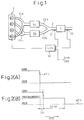
- Fig. 1 is a drawing schematically illustrating the general configuration of an embodiment of the present invention when it is applied to an internal combustion engine for an automobile.
- reference numeral 1 represents an internal combustion engine for an automobile.
- the engine 1 is an internal combustion engine (in this embodiment, the engine is a four-cycle four-cylinder engine having No. 1 through No. 4 cylinders).
- the cylinders of the engine which are not in successive firing order form two groups of cylinders, and each group of cylinders is connected to a separate branch exhaust gas passage. Namely, since the firing order of the engine 1 is 1-3-4-2, the No. 1 and No. 4 cylinders are connected to a branch exhaust gas passage 22a via an exhaust gas manifold 21a and the No. 2 and No. 3 cylinders are connected to a branch exhaust gas passage 22b via an exhaust gas manifold 21b.
- three-way catalysts 5a and 5b having relatively small capacities are disposed on the respective branch exhaust gas passage.
- the three-way catalyst 5a and 5b are capable of removing three pollutants in the exhaust gas, i.e., CO, HC and NO X , at the same time when the air-fuel ratio of the exhaust gas flowing into the catalyst 5a and 5b is in a narrow range including the stoichiometric air-fuel ratio.
- the three-way catalyst 5a and 5b are capable of reducing NO X in the exhaust gas when the air-fuel ratio of the exhaust gas is lower than the above-noted range (i.e., when the air-fuel ratio is rich), and is capable of oxidizing HC and CO in the exhaust gas when the air-fuel ratio of the exhaust gas is higher than the above-noted range (i.e., when the air-fuel ratio is lean).
- the branch exhaust gas passages 22a and 22b merge into a common exhaust gas passage 2 downstream of the three-way catalysts 5a and 5b.
- a NO X occluding and reducing catalyst 7 is disposed on the common exhaust gas passage 2.
- the NO X occluding and reducing catalyst 7 is explained later in detail.
- an upstream air-fuel ratio sensor 31 and a downstream air-fuel ratio sensor 33 are disposed in the common exhaust gas passage 2 at the inlet and outlet of the NO X occluding and reducing catalyst 7, respectively.
- the air-fuel ratio sensors 31 and 33 are linear air-fuel ratio sensors which generate continuous output signals having one-to-one correspondence with the air-fuel ratio of the exhaust gas.
- Reference numeral 30 in Fig. 1 designates an electronic control unit (ECU) of the engine 1.
- the ECU 30 may be constructed as a microcomputer of a known type including a read-only memory (ROM), a random-access memory (RAM), a microprocessor (CPU) and input/output ports all connected to each other by a bi-directional bus.
- the ECU 30 performs basic control of the engine 1 such as a fuel injection control and an ignition control. Further, the ECU 30 in this embodiment acts as various means stated in the claims such as the air-fuel ratio control means and the evaluating means.
- air-fuel ratio signals from the upstream and downstream air-fuel ratio sensors 31 and 33 are supplied to the input port of the ECU 30 via an analog to digital (AD) converter (not shown). Further, signals representing the engine operating condition such as the speed of the engine 1 and the intake air pressure are supplied to the input port from various sensors (not shown).
- the output port of the ECU 30 is connected to the fuel injection valves and the ignition plugs of the respective cylinders of the engine in order to control the fuel injection amount, fuel injection timing and the ignition timing of the engine 1.
- the ECU 30 operates the engine 1 in the normal operation (i.e., when the evaluating operation of the ability of the NO X occluding and reducing catalyst is not performed) at a lean air-fuel ratio in most of the operating range, and performs rich spike operations periodically in order to operate the engine 1 at a rich air-fuel ratio for a short time.
- the ECU 30 changes the operating air-fuel ratio of the engine from a lean air-fuel ratio to a predetermined target rich air-fuel ratio and, after maintaining the air-fuel ratio at the target rich air-fuel ratio for a predetermined period, returns the operating air-fuel ratio to a lean air-fuel ratio.
- the NO X occluding and reducing catalyst in this embodiment comprises precious metals such as platinum (Pt) rhodium (Rh), and at least one substance selected from alkali metals such as potassium (K), sodium (Na), lithium (Li) and cesium (Cs); alkali-earth metals such as barium (Ba) and calcium (Ca); and rare-earth metals such as lanthanum (La) and yttrium (Y).
- the NO X occluding and reducing catalyst absorbs NO X (nitrogen oxide) in the exhaust gas when the air-fuel ratio of the exhaust gas flowing into the catalyst is lean, and releases the absorbed NO X when the oxygen concentration of the exhaust gas flowing through the catalyst becomes low.
- the NO X occluding and reducing catalyst performs the absorbing and releasing operation of NO X in the exhaust gas in which NO X in the exhaust gas is absorbed by the NO X occluding and reducing catalyst when the air-fuel ratio of the exhaust gas is lean and, when the air-fuel ratio of the exhaust gas becomes stoichiometric or rich, NO X is released from the NO X occluding and reducing catalyst and reduced.
- the NO X occluding and reducing catalyst absorbs and holds NO X therein in the form of nitric acid combined with absorbent such as BaO, the NO X occluding and reducing catalyst cannot absorb NO X when the absorbent is saturated with nitric acid ions. If the NO X occluding and reducing catalyst is saturated with nitric acid ions, NO X in the exhaust gas passes through the NO X occluding and reducing catalyst without being absorbed and diffuses into the atmosphere even if the air-fuel ratio of the exhaust gas is lean.
- a rich spike operation is performed after the engine has been operated at a lean air-fuel ratio for a predetermined period.
- the operating air-fuel ratio of the engine is switched to a rich air-fuel ratio and, after the rich air-fuel ratio operation of the engine is continued for a short period, again switched to the lean air-fuel ratio. Since the NO X absorbed in the NO X occluding and reducing catalyst is released and reduced during the rich air-fuel ratio operation, saturation of the NO X occluding and reducing catalyst with the absorbed NO X does not occur.
- the rich spike operation is carried out when the amount of the NO X absorbed in the NO X occluding and reducing catalyst reaches a predetermined value.
- the rich spike operation since it is considered that the amount of the NO X absorbed in the NO X occluding and reducing catalyst is proportional to the length of a lean air-fuel ratio operation of the engine, the rich spike operation may be carried out when the engine is operated at a lean air-fuel ratio for a predetermined period.
- the amount of NO X absorbed in the NO X occluding and reducing catalyst is proportional to the amount of lean air-fuel ratio exhaust gas flowing into the catalyst
- the rich spike operation may be carried out when the cumulative amount of the exhaust gas flowing into the catalyst reaches a predetermined value.
- a cumulative amount of the revolution of the engine may be used as a parameter representing the cumulative amount of the exhaust gas, and the rich spike operation may be carried out when the cumulative engine revolution reaches a predetermined value.
- the rich spike operation may be carried out when the cumulative amount of NO X in the exhaust gas flowing into the catalyst reaches a predetermined value.
- a NO X generation rate the amount of NO X emitted from the engine per unit time
- the engine operating condition such as engine load and speed
- the ECU 30 calculates the NO X generation rate at predetermined intervals based on the engine operating condition, and carries out the rich spike operation when the cumulative value of the calculated NO X generation rate reaches a predetermined value.
- the interval between the rich spike operations is determined using one of the methods explained above.
- the NO X occluding and reducing catalyst deteriorates for various reasons and, when the NO X occluding and reducing catalyst deteriorates, the capacity for absorbing NO X also decreases. For example, if the NO X occluding and reducing catalyst is exposed to a high temperature, the growth of the particles of the absorbent (such as barium oxide BaO) in the NO X occluding and reducing catalyst due to sintering occurs and the sizes of the particles become larger. The ability of the absorbent deteriorates and the maximum NO X absorbing capacity decreases as the sizes of the absorbent particles become larger.
- the absorbent such as barium oxide BaO
- the NO X released from the absorbent is reduced on the surface of the catalytic components (such as platinum Pt) of the NO X occluding and reducing catalyst. Therefore, when the ability of the catalytic components as a reducing catalyst deteriorates, the NO X released from the absorbent passes through the NO X occluding and reducing catalyst without being reduced even if the maximum NO X absorbing capacity of the NO X occluding and reducing catalyst has not deteriorated. Therefore, in order to prevent NO X from diffusing into the atmosphere, it is necessary to evaluate an ability of the NO X occluding and reducing catalyst including both the maximum NO X absorbing capacity and the ability as a reducing catalyst.
- an ability of the NO X occluding and reducing catalyst is evaluated by evaluating both the NO X absorbing capacity of the NO X occluding and reducing catalyst and the ability of the NO X occluding and reducing catalyst as a reducing catalyst using the method explained hereinafter.
- the NO X absorbing capacity of the NO X occluding and reducing catalyst is evaluated by using the following two independent methods (A) and (B).
- the term "the air-fuel ratio of the upstream exhaust gas” means the air-fuel ratio of the exhaust gas flowing into the NO X occluding and reducing catalyst and the term "the air-fuel ratio of the downstream exhaust gas” means the air-fuel ratio of the exhaust gas flowing out from the NO X occluding and reducing catalyst.
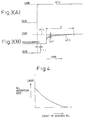
- Figs. 2(A) and 2(B) illustrate the evaluation by the above-noted method (A).
- Fig. 2(A) shows the change in the air-fuel ratio of the upstream exhaust gas detected by the upstream air-fuel ratio sensor 31 when the operating air-fuel ratio of the engine is changed from a lean air-fuel ratio to a rich air-fuel ratio.
- Fig. 2(B) shows the change in the air-fuel ratio of the downstream exhaust gas detected by the downstream air-fuel ratio sensor 33 in the same period as Fig. 2(A).
- the air-fuel ratio of the downstream exhaust gas is maintained at a stoichiometric air-fuel ratio during the period in which the NO X occluding and reducing catalyst 7 releases the absorbed NO X (Fig. 2(B)).
- the air-fuel ratio of the downstream exhaust gas changes from a stoichiometric air-fuel ratio to a rich air-fuel ratio only after the NO X occluding and reducing catalyst 7 releases all the absorbed NO X .
- the length of the period in which the air-fuel ratio of the downstream exhaust gas is maintained at a stoichiometric air-fuel ratio corresponds to the amount of NO X absorbed and held in the NO X occluding and reducing catalyst 7 during the lean air-fuel ratio operation. Therefore, the length of the period TSTR can be used as a parameter representing the NO X absorbing capacity of the NO X occluding and reducing catalyst 7.
- a delay TD in Fig. 2(B) represents a time required for the exhaust gas to flow from the position of the upstream air-fuel ratio sensor 31 to the position of the downstream air-fuel ratio sensor 33.
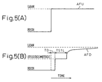
- Figs. 3(A) and 3(B) illustrate the evaluation by the above-noted method (B).
- Figs. 3(A) and 3(B) show the changes in the air-fuel ratios of the upstream exhaust gas detected by the upstream air-fuel ratio sensor 31 and the downstream exhaust gas detected by the downstream air-fuel ratio sensor 33, respectively, when the operating air-fuel ratio of the engine is changed from a rich air-fuel ratio to a lean air-fuel ratio.
- the air-fuel ratio of the downstream exhaust gas is maintained at a stoichiometric air-fuel ratio after the air-fuel ratio of the upstream exhaust gas has been changed to a lean air-fuel ratio also in this case.
- the period TD is a delay explained in Fig. 2(B).
- the air-fuel ratio of the downstream exhaust gas becomes a lean air-fuel ratio after it is maintained at a stoichiometric air-fuel ratio for a certain period, the air-fuel ratio of the downstream exhaust gas does not become the same as that of the upstream exhaust gas.
- Fig. 3(A) and 3(B) the air-fuel ratio of the downstream exhaust gas is maintained at a stoichiometric air-fuel ratio after the air-fuel ratio of the upstream exhaust gas has been changed to a lean air-fuel ratio also in this case.
- the period TD is a delay explained in Fig. 2(B).
- the air-fuel ratio of the downstream exhaust gas takes the value lower than the air-fuel ratio of the upstream exhaust gas, and gradually approaches the air-fuel ratio same as that of the upstream exhaust gas (Fig. 3(B), the period A). Namely, when the air-fuel ratio of the upstream exhaust gas is changed from a rich air-fuel ratio to a lean air-fuel ratio, the air-fuel ratio of the downstream exhaust gas deviates to a rich side from the air-fuel ratio of the upstream exhaust gas for a certain period.
- the deviation of the air-fuel ratio of the downstream exhaust gas is caused by the absorption of NO X in the exhaust gas by the NO X occluding and reducing catalyst 7.
- NO X in the exhaust gas is absorbed in the absorbent BaO of the NO X occluding and reducing catalyst 7 in the form of a nitrate Ba(NO 3 ) 2 by the following reaction. 2NO + O 2 ⁇ 2NO 2 BaO + 2NO 2 + (1/2)O 2 ⁇ Ba(NO 3 ) 2
- the NO X occluding and reducing catalyst 7 uses (3/4) moles of oxygen to absorb 1 mole of NO. Therefore, when the NO X occluding and reducing catalyst 7 absorbs NO X in the exhaust gas, the partial pressure of O 2 in the exhaust gas decreases since the O 2 in the exhaust gas is used by the NO X occluding and reducing catalyst 7.
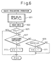
- Fig. 4 shows the change in the absorption rate of NO X (the amount of NO X absorbed per unit time) of NO X occluding and reducing catalyst in accordance with the amount of NO X absorbed and held in the NO X occluding and reducing catalyst.
- the absorption rate of NO X decreases as the amount of NO X held in the NO X occluding and reducing catalyst increases, and becomes zero when the NO X occluding and reducing catalyst is saturated with the absorbed NO X . Therefore, the length of the period A in Fig.
- the cumulated value of the deviation DAF i.e., the area of the hatched portion in Fig. 3(B)
- the NO X absorbing capacity is first evaluated using the above-explained method (A) when the operating air-fuel ratio of the engine is changed from a lean air-fuel ratio to a rich air-fuel ratio, and evaluated again using the above-explained method (B) when the operating air-fuel ratio of the engine is returned to a lean air-fuel ratio from a rich air-fuel ratio.
- the evaluation of the catalytic ability (the ability as a reducing catalyst) of the NO X occluding and reducing catalyst is explained.
- the catalytic ability is evaluated by, (C) the method based on the length of the period in which the air-fuel ratio of the downstream exhaust gas is maintained at a stoichiometric air-fuel ratio after the air-fuel ratio of the upstream exhaust gas has changed from a rich air-fuel ratio to a lean air-fuel ratio.
- Figs. 5(A) and 5(B) illustrate the evaluation of the catalytic ability by the above-noted method (C).
- Figs. 5(A) and 5(B) are similar diagrams as Figs. 3(A) and 3(B) which show the changes in the air-fuel ratios of the upstream exhaust gas detected by the upstream air-fuel ratio sensor 31 and the downstream exhaust gas detected by the downstream air-fuel ratio sensor 33, respectively, when the operating air-fuel ratio of the engine is changed from a rich air-fuel ratio to a lean air-fuel ratio.
- the engine was also operated at a rich air-fuel ratio for a sufficiently long period before the operating air-fuel ratio is changed to a lean air-fuel ratio so that the air-fuel ratio of the downstream exhaust gas has become a rich air-fuel ratio when the operating air-fuel ratio of the engine is switched to a lean air-fuel ratio.
- the air-fuel ratio of the downstream exhaust gas When the air-fuel ratio of the upstream exhaust gas is changed from a rich air-fuel ratio to a lean air-fuel ratio, the air-fuel ratio of the downstream exhaust gas, after the delay time TD has lapsed, changes to a stoichiometric air-fuel ratio and stays there for a certain period (TSTL in Fig. 5(B)).
- TSTL in Fig. 5(B) The reason why the air-fuel ratio of the downstream exhaust gas is maintained at a stoichiometric air-fuel ratio for a certain period when the air-fuel ratio of the upstream exhaust gas changes from a rich air-fuel ratio to a lean air-fuel ratio is explained as follows.
- the length of the period corresponds to the amount of HC and CO oxidized on the surfaces of the catalytic components, i.e., the ability of the NO X occluding and reducing catalyst as an oxidizing catalyst.
- the time TSTL can be used as a parameter representing the ability of the NO X occluding and reducing catalyst as a reducing catalyst.
- the ability of the NO X occluding and reducing catalyst including the NO X absorbing capacity and the catalytic ability as a reducing catalyst is evaluated using the above explained methods (A), (B) and (C). Namely, when the operating air-fuel ratio of the engine is switched to a rich air-fuel ratio after operating the engine at a lean air-fuel ratio for a predetermined time, the NO X absorbing capacity is evaluated by the above-explained method (A). After the evaluation by the method (A) is completed, the operating air-fuel ratio is again changed to a lean air-fuel ratio and the evaluation of the catalytic ability by the method (C) is carried out. Further, the evaluation of the NO X absorbing capacity by the method (B) is carried out after the evaluation by the method (C) is completed.
- Fig. 6 is a flowchart illustrating a basic operation for evaluating the ability of the NO X occluding and reducing catalyst according to the present embodiment. This operation is performed by a routine executed by the ECU 30 at predetermined intervals.
- parameters representing the engine operating condition and the exhaust gas condition are read from the respective sensors.
- the temperature T CAT of the NO X occluding and reducing catalyst 7 may be directly detected by a temperature sensor disposed in the catalyst bed of the NO X occluding and reducing catalyst 7 or may be estimated from the exhaust gas temperature and exhaust gas flow (further, the exhaust gas temperature and flow may be calculated from the engine load condition using the engine speed NE and the intake airflow GA).
- the amount GNOX of the NO X currently held in the NO X occluding and reducing catalyst 7 is read in.
- the amount GNOX is calculated based on the cumulative value of the engine revolutions or the cumulated amount of the NO X emitted from the engine.
- step 605 it is determined whether the value of the evaluating operation flag XD is set at 1.
- step 607 if the engine speed NE, intake air amount GA and the degree of opening of the throttle valve TH are all stable and within predetermined ranges, and if the temperature T CAT of the NO X occluding and reducing catalyst 7 is within a predetermined range, it is determined that the conditions for performing the evaluating operation are satisfied.
- the value of the flag XD is set to 1 at step 613.
- the flag XD is set to 1
- the evaluating operation of the NO X occluding and reducing catalyst 7 is performed as explained later, and steps 607 to 613 are not performed unless the value of the flag XD is reset to 0.
- Steps 609 and 611 are steps for performing the rich spike operation. Namely, at step 609, it is determined whether GNOX, the amount of NO X , reaches a predetermined value A, and if GNOX ⁇ A, a rich spike flag FR is set to 1 at step 611. When the flag FR is set at 1, the operating air-fuel ratio of the engine 1 is changed to a lean air-fuel ratio for a short period by a routine executed by the ECU 30, and the NO X absorbed in the NO X occluding and reducing catalyst is released and reduced.
- the basic operation in Fig. 6 starts the evaluating operation when the conditions are satisfied, and performs the rich spike operation in accordance with the amount of NO X absorbed and held in the NO X occluding and reducing catalyst when the conditions for the evaluating operation are not satisfied.
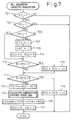
- Fig. 7 is a flowchart illustrating the evaluating operation of the NO X absorbing capacity based on the method (A) as explained before. This operation is performed by a routine performed by the ECU 30 at regular intervals.
- the NO X absorbing capacity of the NO X occluding and reducing catalyst 7 is evaluated by calculating the time TSTR in Fig. 2(B), i.e., the length of the period in which the air-fuel ratio of the downstream exhaust gas is maintained at a stoichiometric air-fuel ratio after the air-fuel ratio of the upstream exhaust gas was changed from a rich air-fuel ratio to a lean air-fuel ratio.
- XRI is a flag used to perform steps 709 and 711 only once when XR ⁇ 1 at step 703. If XRI ⁇ 1 at step 705, flag XRI is set to 1 at step 707 and a rich air-fuel ratio operation flag XAF is set to 1 at step 709. Further, the values of counters RCU and RCD are both cleared. When the rich air-fuel ratio operation flag XAF is set to 1, the fuel injection amount of the engine 1 is adjusted by a fuel injection routine performed by the ECU 30 so that the operating air-fuel ratio of the engine becomes a predetermined rich air-fuel ratio.
- step 713 it is determined whether the air-fuel ratio AFU of the upstream exhaust gas detected by the upstream air-fuel ratio sensor 31 is within a predetermined range between B and C.
- the range B-C is a relatively narrow air-fuel ratio range around the stoichiometric air-fuel ratio, i.e., at step 713, it is determined whether the air-fuel ratio of the upstream exhaust gas is in a narrow range around the stoichiometric air-fuel ratio. If the air-fuel ratio of the upstream exhaust gas is within a narrow range around the stoichiometric air-fuel ratio, the value of the counter RCU is increased by ⁇ T at step 715. ⁇ T is a interval at which the operation in Fig. 7 is carried out.
- the value of the counter RCU represents the length of the period in which the air-fuel ratio of the upstream exhaust gas is maintained within a narrow air-fuel ratio range around the stoichiometric air-fuel ratio.
- Steps 717 and 719 are operation similar to those of steps 713 and 715. Namely, by performing steps 717 and 719, the value of the counter RCD represents the period in which the air-fuel ratio of the downstream exhaust gas is maintained within a narrow range around the stoichiometric air-fuel ratio.
- AFD in step 717 is the air-fuel ratio of the downstream exhaust gas detected by the downstream air-fuel ratio sensor 33 and the air-fuel ratio range D-E is a narrow range around the stoichiometric air-fuel ratio.
- step 721 is performed.
- TSTR is obtained by subtracting RCU from RCD.
- the time TSTR corresponds to the NO X absorbing capacity of the NO X occluding and reducing catalyst.
- the value of TSTR changes in accordance with the conditions of the exhaust gas (for example, temperature of the exhaust gas) even though the NO X absorbing capacity of the NO X occluding and reducing catalyst is the same.
- Fig. 8 is a diagram illustrating the change in the maximum NO X absorbing capacity of a new (not deteriorated) NO X occluding and reducing catalyst in accordance with the temperature T CAT of the NO X occluding and reducing catalyst. As is seen from Fig. 8, the maximum NO X absorbing capacity largely changes when the temperature T CAT changes.
- the calculated value of TSTR must be converted to the value under a reference catalyst temperature in order to evaluate the NO X absorbing capacity of the NO X occluding and reducing catalyst.
- the time TSTR also changes in accordance with the air-fuel ratio and the flow rate of the exhaust gas flowing into the NO X occluding and reducing catalyst.
- the air-fuel ratio of the exhaust gas is low, or the flow rate of the exhaust gas is high, the amount of HC and CO flowing into the NO X occluding and reducing catalyst per unit time becomes large. Therefore, in this case, the amount of NO X released from the catalyst per unit time also becomes large. Namely, the time TSTR becomes shorter as the air-fuel ratio of the exhaust gas becomes lower or the flow rate of the exhaust gas becomes higher even though the amount of NO X absorbed in the catalyst is the same.
- Fig. 9 is a diagram showing the change in the time TSTR of a new NO X occluding and reducing catalyst in accordance with the flow rate of the exhaust gas (i.e., the flow rate GA of the intake air). As is seen from Fig. 9, the time TSTR becomes shorter as the flow rate GA increases.
- TREF is the value of TSTR of a new NO X occluding and reducing catalyst when the flow rate is a reference value GAREF and TGA is the value of TSTR of a new NO X occluding and reducing catalyst under the current flow rate GA.
- the values of the flag XRI and XR are set to 1 to indicate that the evaluating operation in Fig. 7 is completed and, when the operation is next performed, the operation terminates immediately after step 703.
- Fig. 10 is a flowchart showing the evaluating operation of the catalytic ability of the NO X occluding and reducing catalyst based on the method (C) as explained before. This operation is performed by a routine executed by the ECU 30 at regular intervals.
- the catalytic ability is evaluated when the operating air-fuel ratio is changed from a rich air-fuel ratio to a lean air-fuel ratio after the evaluating operation in Fig. 7 was completed.
- XL is a flag representing whether the evaluation of the catalytic ability is completed.
- the flag XL has a function similar to that of the flag XR in Fig. 7.
- the XLI is a flag having a function similar to that of the flag XRI in Fig. 7, i.e., the function for performing steps 1005 to 1011 only once.
- step 1005 it is determined whether the conditions for performing the evaluating operation are satisfied.
- the conditions determined at step 1005 are, (a) the value of the flag XD is set at 1 and, (b) the value of the flag XR is set at 1, i.e., the evaluating operation in Fig. 7 has been completed.
- the flag XLI is set to 1 at step 1007 and the flag XAF is set to 0 at step 1009.
- the flag XAF is set to 0
- the fuel injection amount of the engine 1 is adjusted by the fuel injection routine separately performed by the ECU 30 so that the operating air-fuel ratio of the engine 1 becomes a predetermined lean air-fuel ratio.
- the values of counters OCU and OCD are cleared.
- the counters OCU and OCD are the counters having functions the same as those of the counters RCU and RCD in Fig. 7.
- Steps 1013 to 1027 are the operations similar to those of steps 713 to 727 in Fig. 7.
- the air-fuel ratio ranges G-H in step 1013 and J-K in step 1017 are narrow ranges around the stoichiometric air-fuel ratio.
- TSTL in step 1021 is the length of the period in which the air-fuel ratio of the downstream exhaust gas is maintained at the stoichiometric air-fuel ratio and, LTCAT, LGA (step 1023) are a temperature correction factor and a flow rate correction factor similar to KTCAT and KGA in Fig. 7.
- LTCAT and LGA are determined based on the relationships similar to Figs. 8 and 9.
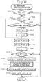
- Fig. 11 is a flowchart illustrating the evaluating operation of the NO X absorbing capacity of the NO X occluding and reducing catalyst 7 based on the method (B) explained before. This operation is carried out by a routine executed by the ECU 30 at regular intervals. In this operation, the NO X absorbing capacity is obtained by calculating the cumulative value of the difference between the air-fuel ratios of the upstream and downstream exhaust gas. The calculated cumulative value is also corrected in accordance with the exhaust gas conditions.
- the air-fuel ratio of the upstream exhaust gas AFU and the air-fuel ratio of the downstream exhaust gas AFD are stored in RAM as AFUi and AFDi at steps 1111 and 1113, respectively.
- the value of i is increased by 1 every time the operation is carried out (step 1115).
- the difference between AFU and AFD is compared with a predetermined value N (N is a small constant value). If (AFU - AFD) ⁇ N at step 1117, this means that the NO X occluding and reducing catalyst will not absorb NO X any longer and the cumulative value DAFS of the deviation of the air-fuel ratio of the downstream exhaust gas from the air-fuel ratio of the upstream exhaust gas is calculated at step 1119.
- the deviation is defined as (AFUi - AFD(i+k)). Namely, it is assumed that the exhaust gas passing the upstream air-fuel ratio sensor 31 reaches the downstream air-fuel ratio sensor 33 after the operation in Fig. 11 is performed k times.
- the value of k may be changed in accordance with the operating condition (such as exhaust gas velocity in the exhaust gas passage).
- the operation calculates a temperature correction factor OLTCAT and a flow rate correction factor OLGA at step 1121.
- the correction factors OLTCAT and OLGA are calculated based on the relationships similar to those in Figs. 8 and 9.
- the ability of the NO X occluding and reducing catalyst 7 is determined based on CATDOR, CATDOS and CATDOL obtained by the evaluating operations in Figs. 7, 10 and 11.
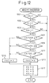
- Fig. 12 is a flowchart for determining the ability of the NO X occluding and reducing catalyst. This operation is performed by a routine executed by the ECU 30 at predetermined intervals.
- Fig. 12 at steps 1201 through 1205, it is determined whether the evaluating operations of Figs. 7, 10 and 11 have been completed based on the values of the flags XR, XL and XUL. If any of these operations has not been completed, the operation in Fig. 12 terminates without determining the ability of the NO X occluding and reducing catalyst 7.
- this operation determines whether the NO X absorbing capacity CATDOR evaluated by the operation in Fig. 7 is not smaller than a predetermined reference value P at step 1207. Similarly, at steps 1209 and 1211, it is determined whether the catalytic ability CATDOS evaluated by the operation in Fig. 10 and the NO X absorbing capacity CATDOL evaluated by the operation in Fig. 11 are not smaller than the reference values Q and R, respectively. If none of CATDOR, CATDOS, CATDOL is smaller than the reference values at steps 1207 through 1211, the value of a failure flag FAIL is set to 0 at step 1213.
- the value of the failure flag FAIL is set to 1 at step 1215.
- the values of the flags XD, XR, XL and XU are all reset to 0 in order to indicate that the evaluation of the ability has been completed. Further, if the failure flag FAIL is set to 1, the ECU 30 activates an alarm in order to warn the driver that the NO X occluding and reducing catalyst has deteriorated.
- the NO X absorbing capacity of the NO X occluding and reducing catalyst is evaluated when the air-fuel ratio of the upstream exhaust gas changes to both directions (i.e., from lean to rich and from rich to lean), the NO X absorbing capacity is precisely evaluated.
- the catalytic ability of the NO X occluding and reducing catalyst as well as the NO X absorbing capacity can be evaluated by one changing operation of the operating air-fuel ratio of the engine and the evaluation of the ability of the NO X occluding and reducing catalyst including both the NO X absorbing capacity and the catalytic ability can be performed.
- the arrangement of the exhaust gas purification device may be the same as that in Fig. 1.
- the upstream air-fuel ratio sensor since the upstream air-fuel ratio sensor is less important, the upstream air-fuel ratio sensor may be disposed at a portion different from the air-fuel ratio sensor 31 in Fig. 1.
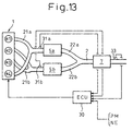
- two upstream air-fuel ratio sensors 31a and 31b may be disposed in the branch exhaust gas passage upstream of the three-way catalyst 5a and 5b as illustrated in Fig. 13.
- an O 2 sensor which generates a signal of different level according to whether the exhaust gas air-fuel ratio is a lean air-fuel ratio or a rich air-fuel ratio, instead of the linear air-fuel ratio sensor in Fig. 1 may be used as the upstream and downstream air-fuel ratio sensors.
- the ECU 30 evaluates the NO X absorbing capacity of the NO X occluding and reducing catalyst, i.e., the degree of deterioration of the NO X occluding and reducing catalyst, and adjusts the length of the rich air-fuel ratio operation period in the rich spike operation and/or the interval between the rich spike operations in accordance with the degree of deterioration of the NO X occluding and reducing catalyst.
- the degree of deterioration i.e., the NO X absorbing capacity of the NO X occluding and reducing catalyst 7 is evaluated during the rich spike operation in a manner similar to the method (A) in the previous embodiment.
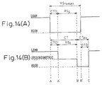
- Figs. 14(A) and 14(B) are diagrams similar to Figs. 2(A) and 2(B) illustrating the change in the operating air-fuel ratio of the engine and the air-fuel ratio of the downstream exhaust gas detected by the downstream air-fuel ratio sensor 33 during the rich spike operation.
- the length of the rich operation period in the rich spike operation is set at a constant value RS TARGET regardless of the air-fuel ratio of the downstream exhaust gas when evaluating the degree of deterioration of the NO X occluding and reducing catalyst 7.
- the air-fuel ratio of the downstream exhaust gas is maintained at a lean air-fuel ratio until the rich air-fuel ratio exhaust gas arrives the NO X occluding and reducing catalyst (a delay period CTD in Figs. 14(A) and 14(B)).
- the air-fuel ratio of the downstream exhaust gas changes to a stoichiometric air-fuel ratio (point A' in Fig. 14(B)) and stays there for a period RS 0 before it changes to a rich air-fuel ratio at point B in Fig. 14(B).
- the length of the period RS 0 is the actual time required for the NO X occluding and reducing catalyst to release all the NO X it has absorbed. This time is hereinafter referred to as "an actual rich spike time".
- an actual rich spike time is hereinafter referred to as "an actual rich spike time".
- the air-fuel ratio of the downstream exhaust gas is maintained at a rich air-fuel ratio until the delay time CTD has lapsed after the rich spike operation has ended (the point C in Fig. 14(B)). Therefore, since the rich spike operation period RS TARGET is longer than the actual rich spike time RS 0 in Figs. 14(A) and 14(B) , the rich spike operation period RS TARGET is in excess of actually required rich spike time RS 0 by CT EX .
- the actual rich spike time RS 0 corresponds to the current NO X absorbing capacity of the NO X occluding and reducing catalyst 7.
- the time RS 0 changes in accordance with the engine operating conditions such as exhaust gas temperature and flow rates even though the NO X absorbing capacity of the NO X occluding and reducing catalyst and the rich air-fuel ratio during the rich spike operation are the same.
- a reference rich spike time RS REF which is a time required for a new (not deteriorated) NO X occluding and reducing catalyst to release all the absorbed NO X under the current operating conditions of the engine is used for evaluating the degree of deterioration of the NO X occluding and reducing catalyst.
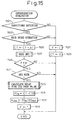
- Fig. 15 is a flowchart explaining the evaluating operation of the degree of deterioration of the NO X occluding and reducing catalyst in this embodiment.
- Step 1501 in Fig. 15 designates the determination whether the conditions for evaluation of the deterioration is satisfied.
- the conditions determined at step 1501 are, for example, (a) that the engine operating condition is stable, i.e., the engine load and engine speed are constant and (b) that the recovery operation (explained later) is not in progress. If one or more of the conditions (a) and (b) is not satisfied, the operation terminates after setting the value of a flag F to 0 at step 1521 and clearing the value of a counter CT at step 1523.
- step 1501 it is determined whether the rich spike operation is not in progress at step 1503, and if the rich spike operation is not in progress, the operation terminates after executing steps 1521 and 1523. If the rich spike operation is in progress at step 1503, the value of the counter CT is increased by ⁇ T at step 1505. ⁇ T is the interval at which this operation is performed. Since the counter CT is reset to 0 at step 1523 when the rich spike operation is not performed, the value of the counter CT at step 1505 agrees with the time that has lapsed after the rich spike operation was started.
- the air-fuel ratio of the downstream exhaust gas AFS is read from the downstream air-fuel ratio sensor 33 and, at step 1509, it is determined whether the value of the flag F is 0. If F ⁇ 0 at step 1509, the operation terminates without executing steps 1511 through 1519. Namely, the evaluating operation is performed only once after the conditions in step 1501 were satisfied.
- Step 1509 it is determined whether the air-fuel ratio of the downstream exhaust gas AFS is at a rich air-fuel ratio.
- the air-fuel ratio of the downstream exhaust gas AFS becomes a rich air-fuel ratio after the delay time CTD has lapsed, and stays at the rich air-fuel ratio until all the absorbed NO X is released from the NO X occluding and reducing catalyst 7.
- Step 1511 monitors the AFS in order to determine the changing point (the point B in Fig. 14(B)) to the rich air-fuel ratio.
- AFS is not a rich air-fuel ratio at step 1511, this means that absorbed NO X still remains in the NO X occluding and reducing catalyst and the operation terminates without executing steps 1513 through 1519.
- the delay time CTD is the time required for the exhaust gas to flow from the engine 1 to the position of the downstream air-fuel ratio sensor 33. This delay time changes in accordance with the engine load and speed (i.e., the velocity of the exhaust gas in the exhaust gas passage).
- the relationship between the delay time CTD and the engine operating conditions i.e., the engine load and speed
- the delay time CTD is read from the numerical table using the current engine operating condition (PM and NE).
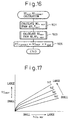
- the reference rich spike time RS REF is the time corresponding to RS 0 when a new NO X occluding and reducing catalyst is used under the current engine operating condition, and obtained by the operation in Fig. 16.
- the time RS 0 corresponds to the amount of NO X absorbed in the NO X occluding and reducing catalyst 7 under the current engine operating conditions, i.e., the maximum NO X absorbing capacity of the catalyst 7.
- step 1601 the maximum amount of NO X absorbed and held by a new (not deteriorated) NO X occluding and reducing catalyst (i.e., the reference NO X amount NO Xref ) under the current temperature T CAT of the actual NO X occluding and reducing catalyst 7 and the air-fuel ratio of the exhaust gas AFL during the current lean air-fuel ratio operation of the engine 1 is calculated.
- the maximum amount of NO X absorbed and held by the NO X occluding and reducing catalyst changes in accordance with the air-fuel ratio of the lean air-fuel ratio operation and the temperature of the catalyst.
- the reference NO X amount NO Xref is previously obtained by experiment in which the maximum amount of NO X absorbed by a new NO X occluding and reducing catalyst is measured under various air-fuel ratio and temperature conditions.
- the reference NO X amount NO Xref is stored in the ROM of the ECU 30 in the form of a numerical table using the AFL (the air-fuel ratio of the exhaust gas during the lean air-fuel ratio operation of the engine) and the temperature T CAT of the NO X occluding and reducing catalyst as parameters.
- the reference NO X amount NO Xref is read from the numerical table based on the current temperature T CAT of the catalyst 7 and the air-fuel ratio AFL of the exhaust gas during the current lean air-fuel ratio operation.
- the reference rich spike time RS REF which is required for a new NO X occluding and reducing catalyst to release the reference NO X amount NO Xref obtained at step 1601 is calculated.
- the reference rich spike time RS REF also changes in accordance with the flow rate of the exhaust gas even if the NO X amount NO Xref is the same. For example, when the flow rate of the exhaust gas is low, the time RS REF becomes longer even if the amount NO Xref is the same.
- Fig. 17 shows the relationship between the time RS REF and the amount NO Xref when the engine speed NE changes. In Fig. 17, the engine speed NE is used as a parameter representing the exhaust gas flow rate since the exhaust gas flow rate changes in accordance with the engine speed.
- the reference rich spike time RS REF is obtained from the relationship in Fig. 17 based on the reference NO X amount and the engine speed NE.
- the obtained value of RS REF is used for calculating the factor K det in the operation in Fig. 15.
- the length of the rich air-fuel ratio operation of the engine during the rich spike operation is set to RS TARGET calculated at step 1605. Therefore, the length of the period of the rich air-fuel ratio operation during the rich spike operation matches the amount of NO X actually absorbed in the NO X occluding and reducing catalyst 7, and the excess rich air-fuel ratio operation such as the period CT EX in Fig. 14(B) is eliminated.
- the interval between the rich spike operations is adjusted so that the interval becomes proportional to the value K det .
- the interval may be adjusted by multiplying T 0 by the factor K det .
- the predetermined values may be adjusted by multiplying the factor K det .
- the factor K det represents the degree of the deterioration of the NO X occluding and reducing catalyst, i.e., the NO X absorbing capacity of the NO X occluding and reducing catalyst.
- the performance the ability for purifying NO X in the exhaust gas
- the rich spike operation for example, the rich spike period and the interval between the rich spike operation
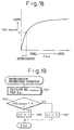
- Fig. 18 shows the change in the performance NO XREDAVE of the whole exhaust gas purification device in accordance with the degree of deterioration of the NO X occluding and reducing catalyst K det .
- the degree of deterioration is small (i.e., K det is large)
- the performance (the NO X purification ability) NO XREDAVE of the device does not change largely even if the deterioration of the catalyst proceeds (i.e., K det becomes smaller).
- the allowable limit of the deterioration of the NO X occluding and reducing catalyst must be determined based on the performance of the device as a whole. In this embodiment, therefore, the NO X occluding and reducing catalyst is determined as having deteriorated beyond the allowable limit when the purification performance of the whole device NO XREDAVE becomes lower than the reference value ⁇ in Fig. 18.
- recovery operations are performed in order to restore the NO X absorbing capacity of the NO X occluding and reducing catalyst.
- Fig. 19 is a flowchart illustrating the determining operation of the deterioration of the NO X occluding and reducing catalyst based on the purification performance of the whole system. This operation is performed by a routine executed by the ECU 30 at regular intervals.
- the purification performance NO XREDAVE is calculated from the deterioration factor K det obtained by the operation in Fig. 15 and the relationship in Fig. 18.
- the reference value ⁇ of the purification performance NO XREDAVE corresponds to the point where the NO XREDAVE starts to fall rapidly. If NO XREDAVE ⁇ ⁇ at step 1903, since this means that the NO X occluding and reducing catalyst has deteriorated beyond the maximum limit, the operation sets the value of a deterioration flag XF to 1.
- the value of the flag XF is set to 0 at step 1907.
- the value of the flag XF may be stored in a nonvolatile memory to prepare for future maintenance and inspection. Further, in this embodiment, recovery operations (decontaminating operations) of the NO X occluding and reducing catalyst, as explained later, are performed when the value of the flag XF is set to 1.
- the deterioration of the NO X occluding and reducing catalyst is caused by various factors. For example, when the size of the absorbent particles becomes larger due to sintering, the NO X absorbing capacity of the NO X occluding and reducing catalyst deteriorates, as explained before. Further, the NO X occluding and reducing catalyst also deteriorates due to SO X contamination and HC contamination.
- SO X sulfur oxides
- the NO X occluding and reducing catalyst absorbs SO X in the exhaust gas by a mechanism identical to that of the NO X absorption and holds SO X in the form of sulfate within the absorbent (such as BaO).
- a sulfate such as BaSO 4 has a higher stability than nitrate, it is difficult to release SO X from the NO X occluding and reducing catalyst by the normal rich spike operation.
- the NO X occluding and reducing catalyst when SO X exists in the exhaust gas, sulfate accumulates in the NO X occluding and reducing catalyst and, as the amount of SO X increases, the NO X absorbing capacity deteriorates.
- the deterioration of the NO X occluding and reducing catalyst caused by the absorbed SO X is referred to as a SO X contamination in order to discriminate it from the normal deterioration (i.e., deterioration caused by the growth of the sizes of the absorbent particles).
- the rate of decrease in the NO X absorbing capacity caused by the SO X contamination is larger than that caused by the normal deterioration.
- deterioration of the NO X occluding and reducing catalyst is also caused by HC in the exhaust gas.
- HC in the exhaust gas attaches to the surfaces of the catalytic components (such as platinum Pt) particles. Therefore, if the operation in such conditions continues for some period, the amount of HC attached to the surfaces of the catalytic particles increases and, eventually, covers a large part of the surfaces of the particles.
- the rate of decrease in the NO X absorbing capacity caused by the HC contamination is many times larger than that caused by the SO X contamination.
- the NO X occluding and reducing catalyst cannot recover from the normal deterioration, the catalyst can recover from the SO X contamination or HC contamination provided that appropriate recovery operations are performed.
- the SO X contamination is caused by the accumulation of sulfate in the absorbent. Sulfate can be dissolved if the rich air-fuel ratio atmosphere continues for a longer time than the normal rich spike operation. Therefore, the NO X occluding and reducing catalyst may recover from the SO X contamination by setting the rich spike period longer and the interval between the rich spike operations shorter than normal rich spike operation.
- the NO X occluding and reducing catalyst may recover from the HC contamination by supplying lean air-fuel ratio exhaust gas to the catalyst and oxidizing (burning) HC on the surface of the catalytic particles. Therefore, it is necessary to set the rich spike period shorter and the interval between the rich spike operation longer than the normal rich spike operation in order for the NO X occluding and reducing catalyst to recover from the HC contamination.
- the type of deterioration is determined using the rate of decrease in the NO X absorbing capacity.
- the rate of decrease in the NO X absorbing capacity due to the normal deterioration is very small, the rate of the change in the value of K det caused by the normal deterioration is very small.
- the rate of change in the value of K det caused by the SO X contamination is relatively large.
- the rate of change in the value of K det caused by the HC contamination is very large. Therefore, in this embodiment, the ECU 30 calculates the rate of change RST in the value of K det , and determines the type of deterioration of the NO X occluding and reducing catalyst based on the value of RST.
- the ECU 30 determines that the deterioration of the NO X occluding and reducing catalyst was caused by the HC contamination and performs the recovery operation suitable for the HC contamination. Further, if RST is smaller than RHC but larger than another predetermined value RSOX, the ECU 30 determines that the deterioration of the NO X occluding and reducing catalyst was caused by the SO X contamination, and performs the recovery operation suitable for the SO X contamination.
- the ECU 30 activates an alarm to warn the driver that the NO X occluding and reducing catalyst must be replaced.
- Fig. 20 is a flowchart explaining the recovery operation of the NO X occluding and reducing catalyst as explained above. This operation is performed by a routine executed by the ECU 30 at regular intervals.
- the condition determined at step 2001 is that a predetermined time has lapsed since the recovery operation is last performed. If the predetermined time has not lapsed, the operation terminates immediately, i.e., the recovery operation is not performed. In this embodiment, if the NO X occluding and reducing catalyst does not recover from the deterioration (i.e., when the value of the flag is not reset to 0), the recovery operation is repeated. However, even if the NO X occluding and reducing catalyst is recovered from the deterioration, it takes some time before the values of K det and the rate of change RST reflects the recovery of the catalyst. Therefore, in order to eliminate the possibility that the recovery operation is repeated even though the NO X occluding and reducing catalyst has recovered from the deterioration, this embodiment does not perform the recovery operation for a predetermined period after the recovery operation was last performed.
- step 2003 determines whether the deterioration flag XF is set at 1.
- step 2003 the operation executes step 2005 to determine whether the value of another flag XRD is set at 1.
- the operation determines whether the rate of change RST in the value of K det is larger than a predetermined value RHC.
- the rate of change RST in the value of K det is calculated by a separate routine performed by the ECU 30 at regular intervals. If RST > RHC at step 2007, since this means that the deterioration was caused by the HC contamination, the operation sets the engine operating parameters at values suitable for the recovery from the HC contamination at step 2009. Namely, at step 2009, a rich spike period correction factor KDRS is set at 0.8, a rich spike interval correction factor KDL is set at 1.2. Further, a stoichiometric air-fuel ratio operation correction factor KST is set at 0.
- the rich spike period correction factor KDRS When the rich spike period correction factor KDRS is set at 0.8, the length of the rich air-fuel ratio operation during the rich spike operation becomes 0.8 times shorter than that of the normal rich spike operation. Further, when the rich spike interval correction factor KDL is set at 1.2, the interval between the rich spike operations becomes 1.2 times longer than that of the normal rich spike operation. Therefore, a lean air-fuel ratio exhaust gas is supplied to the NO X occluding and reducing catalyst 7 for a period longer than the normal operation of the engine.
- the stoichiometric air-fuel ratio operation correction factor KST determines the width of the operating range where the engine is operated at a stoichiometric air-fuel ratio.
- the engine 1 in this embodiment is operated at a lean air-fuel ratio in the normal operating range, the engine 1 is switched to the stoichiometric air-fuel ratio operation in specific operating ranges such as high load operation range.
- the value of the factor KST is set to 1
- the operating range where the engine is operated at a stoichiometric air-fuel ratio is set at a wider range.
- the factor KST is set at 0
- the operating range where the engine stoichiometric air-fuel ratio operation is performed is set in a relatively narrow range. Therefore, the frequency of the lean air-fuel ratio operation of the engine increases.
- step 2015 determines whether the deterioration was caused by the SO X contamination. Namely, at step 2015, it is determined whether RST is larger than the predetermined value RSOX (RSOX is a value smaller than RHC). If RST > RSOX, since this means that the deterioration was caused by the SO X contamination, the operation executes step 2017 to set the values of the factors KDRS, KDL and KST to 1.5, 0.8 and 1, respectively. When KDRS is set at 1.5, the length of the rich air-fuel ratio operation during the rich spike operation becomes 1.5 times longer than that of the normal rich spike operation.
- the rich spike interval correction factor KDL when the rich spike interval correction factor KDL is set at 0.8, the interval between the rich spike operations becomes 0.8 times shorter than that of the normal rich spike operation. Therefore, a rich air-fuel ratio exhaust gas is supplied to the NO X occluding and reducing catalyst 7 for a period longer than the normal operation of the engine. Further, when the value of the factor KST is set to 1, the operating range where the engine is operated at a stoichiometric air-fuel ratio is set at a wider range. Therefore, the frequency of the stoichiometric air-fuel ratio operation of the engine increases.
- the value of the flag XRD is set to 1 (i.e., the recovery operation is in progress) and the value of a counter CR is reset to 0 at step 2013 before the operation terminates. Since the flag XRD is set to 1, when the operation is next performed, operation executes step 2023 after step 2005. Thus, the value of the counter CR is increased by ⁇ T 1 every time the operation is performed. ⁇ T 1 is the interval between the operations performed in Fig. 20. Therefore, the value of the counter CR represents the time lapsed since the recovery operation started.
- step 2015 If RST ⁇ RSOX at step 2015, this means that the deterioration of the NO X occluding and reducing catalyst is not caused by the HC contamination nor the SO X contamination. Therefore, it can be considered that the deterioration of the NO X occluding and reducing catalyst was caused by the normal deterioration. Since it is difficult to recover from the normal deterioration, in this case, the operation executes step 2019 to activate the alarm by setting the value of the flag to 1. Thus, the driver is warned that the NO X occluding and reducing catalyst needs to be replaced.
- Fig. 21 is a flowchart illustrating the operation for determining the timing for terminating the recovery operation. This determining operation is performed by a routine executed by the ECU 30 at regular intervals. In this operation, the recovery operation is terminated when a predetermined time has lapsed since the recovery operation started.
- step 2101 in Fig. 21 it is determined whether the value of the counter CR reaches a predetermined value CR 0 and, if CR ⁇ CR 0 the operation terminates immediately without executing steps 2103 through 2105. Namely, the recovery operation continues until the value of the counter CR reaches CR 0 . If CR ⁇ CR 0 at step 2101, i.e., if the recovery operation is performed for a predetermined time CR 0 , the operation performs step 2103 to reset the value of the flag to 0, and step 2105 to set the values of the factors KDRS, KDL and KST to 1.0, 1.0 and 0, respectively. Therefore, the normal rich spike operation is resumed, and the operating range where the stoichiometric air-fuel ratio operation of the engine is performed is set to a narrow range.
- the deterioration factor K det and the rate of change thereof RST are calculated and, the type of deterioration is determined from RST. Therefore, an appropriate recovery operation can be performed in accordance with the type of the deterioration.
- a NO X occluding and reducing catalyst is disposed in the exhaust gas passage of an engine.
- the NO X occluding and reducing catalyst absorbs NO X in the exhaust gas when the air-fuel ratio of the exhaust gas is at a lean air-fuel ratio and releases and reduces NO X when the air-fuel ratio of the exhaust gas is at a rich air-fuel ratio.
- the air-fuel ratio of the exhaust gas flowing out from the catalyst is detected by an air-fuel ratio sensor disposed in the exhaust gas passage downstream of the catalyst.
- the air-fuel ratio of the exhaust gas flowing out from the catalyst stays at a stoichiometric air-fuel ratio before it changes to a lean air-fuel ratio.
- the length of the period in which the air-fuel ratio of the exhaust gas flowing out from the catalyst stays at a stoichiometric air-fuel ratio corresponds to the magnitude of the ability of the NO X occluding and reducing catalyst as a reducing catalyst.
- the ability of the NO X occluding and reducing catalyst as a reducing catalyst can be precisely evaluated.
Landscapes
- Engineering & Computer Science (AREA)
- Chemical & Material Sciences (AREA)
- Combustion & Propulsion (AREA)
- Mechanical Engineering (AREA)
- General Engineering & Computer Science (AREA)
- Chemical Kinetics & Catalysis (AREA)
- Biomedical Technology (AREA)
- Environmental & Geological Engineering (AREA)
- Analytical Chemistry (AREA)
- General Chemical & Material Sciences (AREA)
- Oil, Petroleum & Natural Gas (AREA)
- Health & Medical Sciences (AREA)
- Exhaust Gas After Treatment (AREA)
- Exhaust Gas Treatment By Means Of Catalyst (AREA)
Applications Claiming Priority (6)
| Application Number | Priority Date | Filing Date | Title |
|---|---|---|---|
| JP25467097 | 1997-09-19 | ||
| JP25467097A JP3460530B2 (ja) | 1997-09-19 | 1997-09-19 | 内燃機関の排気浄化装置 |
| JP25509097A JP3412472B2 (ja) | 1997-09-19 | 1997-09-19 | 内燃機関の排気浄化装置 |
| JP255090/97 | 1997-09-19 | ||
| JP25509097 | 1997-09-19 | ||
| JP254670/97 | 1997-09-19 |
Publications (3)
| Publication Number | Publication Date |
|---|---|
| EP0903479A2 true EP0903479A2 (de) | 1999-03-24 |
| EP0903479A3 EP0903479A3 (de) | 1999-12-29 |
| EP0903479B1 EP0903479B1 (de) | 2003-06-18 |
Family
ID=26541782
Family Applications (1)
| Application Number | Title | Priority Date | Filing Date |
|---|---|---|---|
| EP98117776A Expired - Lifetime EP0903479B1 (de) | 1997-09-19 | 1998-09-18 | Abgasreinigungsvorrichtung für eine Brennkraftmaschine |
Country Status (3)
| Country | Link |
|---|---|
| US (2) | US6138453A (de) |
| EP (1) | EP0903479B1 (de) |
| DE (1) | DE69815611T2 (de) |
Cited By (7)
| Publication number | Priority date | Publication date | Assignee | Title |
|---|---|---|---|---|
| WO2000077355A1 (de) * | 1999-06-09 | 2000-12-21 | Volkswagen Aktiengesellschaft | VERFAHREN ZUR ERFASSUNG EINER SCHÄDIGUNG VON WENIGSTENS EINEM IN EINEM ABGASKANAL EINER VERBRENNUNGSKRAFTMASCHINE ANGEORDNETEN NOx-SPEICHERKATALYSTOR |
| WO2001009490A1 (de) * | 1999-07-31 | 2001-02-08 | Robert Bosch Gmbh | Verfahren zum betreiben einer brennkraftmaschine |
| EP1081348A3 (de) * | 1999-09-01 | 2003-02-26 | Honda Giken Kogyo Kabushiki Kaisha | Abgasemissionssteuerungssystem für eine Brennkraftmaschine |
| EP1188915A3 (de) * | 2000-09-15 | 2004-01-07 | Volkswagen Aktiengesellschaft | Verfahren zur Regelung einer NOx-Regeneration eines NOx-Speicherkatalysators |
| WO2007074071A1 (de) | 2005-12-23 | 2007-07-05 | Robert Bosch Gmbh | Verfahren und vorrichtung zur regeneration einer abgasreinigungsanlage |
| EP2700800A4 (de) * | 2011-04-22 | 2014-10-15 | Nissan Motor | Gasreinigungs-steuervorrichtung für einen verbrennungsmotor |
| FR3118718A1 (fr) * | 2021-01-14 | 2022-07-15 | Etat Français représenté par le Délégué Général pour L'Armement | procédé non destructif de determination de la capacité residuelle d’arrêt d’un filtre adsorbant et banc d’essai associé |
Families Citing this family (51)
| Publication number | Priority date | Publication date | Assignee | Title |
|---|---|---|---|---|
| US6138453A (en) * | 1997-09-19 | 2000-10-31 | Toyota Jidosha Kabushiki Kaisha | Exhaust gas purification device for an internal combustion engine |
| DE19758018A1 (de) * | 1997-12-29 | 1999-07-01 | Volkswagen Ag | Regeneration eines NOx-Speicherkatalysators eines Verbrennungsmotors |
| JP3680611B2 (ja) * | 1999-02-03 | 2005-08-10 | 日産自動車株式会社 | 内燃機関の排気浄化装置 |
| JP3649034B2 (ja) * | 1999-03-25 | 2005-05-18 | 日産自動車株式会社 | エンジンの排気浄化装置 |
| JP3618598B2 (ja) * | 1999-06-03 | 2005-02-09 | 本田技研工業株式会社 | 内燃機関の排気浄化装置 |
| JP2001075527A (ja) * | 1999-09-01 | 2001-03-23 | Sharp Corp | 表示装置 |
| DE19963924A1 (de) * | 1999-12-31 | 2001-07-12 | Bosch Gmbh Robert | Verfahren zum Betreiben eines Speicherkatalysators einer Brennkraftmaschine |
| US6360530B1 (en) | 2000-03-17 | 2002-03-26 | Ford Global Technologies, Inc. | Method and apparatus for measuring lean-burn engine emissions |
| US6438944B1 (en) * | 2000-03-17 | 2002-08-27 | Ford Global Technologies, Inc. | Method and apparatus for optimizing purge fuel for purging emissions control device |
| US6860100B1 (en) | 2000-03-17 | 2005-03-01 | Ford Global Technologies, Llc | Degradation detection method for an engine having a NOx sensor |
| JP2001355485A (ja) * | 2000-06-16 | 2001-12-26 | Isuzu Motors Ltd | 窒素酸化物吸蔵還元型触媒を備えた排気ガス浄化装置 |
| JP3607984B2 (ja) * | 2000-06-26 | 2005-01-05 | トヨタ自動車株式会社 | 車載用内燃機関の排気浄化装置 |
| JP3776299B2 (ja) * | 2000-07-21 | 2006-05-17 | 本田技研工業株式会社 | 内燃機関の排気浄化装置 |
| EP1182340B1 (de) * | 2000-08-22 | 2005-06-08 | Mazda Motor Corporation | Abgasreinigungssystem für eine Brennkraftmaschine |
| US6418711B1 (en) * | 2000-08-29 | 2002-07-16 | Ford Global Technologies, Inc. | Method and apparatus for estimating lean NOx trap capacity |
| US6691507B1 (en) | 2000-10-16 | 2004-02-17 | Ford Global Technologies, Llc | Closed-loop temperature control for an emission control device |
| US6588200B1 (en) | 2001-02-14 | 2003-07-08 | Ford Global Technologies, Llc | Method for correcting an exhaust gas oxygen sensor |
| EP1365137B9 (de) * | 2001-02-26 | 2006-07-12 | Mitsubishi Jidosha Kogyo Kabushiki Kaisha | Abgasreiniger für brennkraftmaschinen |
| US6615577B2 (en) | 2001-06-19 | 2003-09-09 | Ford Global Technologies, Llc | Method and system for controlling a regeneration cycle of an emission control device |
| US6604504B2 (en) | 2001-06-19 | 2003-08-12 | Ford Global Technologies, Llc | Method and system for transitioning between lean and stoichiometric operation of a lean-burn engine |
| US6453666B1 (en) | 2001-06-19 | 2002-09-24 | Ford Global Technologies, Inc. | Method and system for reducing vehicle tailpipe emissions when operating lean |
| US6463733B1 (en) | 2001-06-19 | 2002-10-15 | Ford Global Technologies, Inc. | Method and system for optimizing open-loop fill and purge times for an emission control device |
| US6490860B1 (en) | 2001-06-19 | 2002-12-10 | Ford Global Technologies, Inc. | Open-loop method and system for controlling the storage and release cycles of an emission control device |
| US6691020B2 (en) | 2001-06-19 | 2004-02-10 | Ford Global Technologies, Llc | Method and system for optimizing purge of exhaust gas constituent stored in an emission control device |
| US6650991B2 (en) | 2001-06-19 | 2003-11-18 | Ford Global Technologies, Llc | Closed-loop method and system for purging a vehicle emission control |
| US6539706B2 (en) | 2001-06-19 | 2003-04-01 | Ford Global Technologies, Inc. | Method and system for preconditioning an emission control device for operation about stoichiometry |
| US6467259B1 (en) | 2001-06-19 | 2002-10-22 | Ford Global Technologies, Inc. | Method and system for operating dual-exhaust engine |
| US6553754B2 (en) | 2001-06-19 | 2003-04-29 | Ford Global Technologies, Inc. | Method and system for controlling an emission control device based on depletion of device storage capacity |
| US6694244B2 (en) | 2001-06-19 | 2004-02-17 | Ford Global Technologies, Llc | Method for quantifying oxygen stored in a vehicle emission control device |
| US6546718B2 (en) | 2001-06-19 | 2003-04-15 | Ford Global Technologies, Inc. | Method and system for reducing vehicle emissions using a sensor downstream of an emission control device |
| US6487853B1 (en) | 2001-06-19 | 2002-12-03 | Ford Global Technologies. Inc. | Method and system for reducing lean-burn vehicle emissions using a downstream reductant sensor |
| US6502387B1 (en) | 2001-06-19 | 2003-01-07 | Ford Global Technologies, Inc. | Method and system for controlling storage and release of exhaust gas constituents in an emission control device |
| JP3860981B2 (ja) * | 2001-08-28 | 2006-12-20 | 本田技研工業株式会社 | 内燃機関の排気浄化装置 |
| JP3846375B2 (ja) * | 2002-07-10 | 2006-11-15 | トヨタ自動車株式会社 | 触媒劣化判定方法 |
| JP3873904B2 (ja) * | 2003-02-26 | 2007-01-31 | 日産自動車株式会社 | 内燃機関の排気浄化装置 |
| US6766641B1 (en) * | 2003-03-27 | 2004-07-27 | Ford Global Technologies, Llc | Temperature control via computing device |
| US6854264B2 (en) * | 2003-03-27 | 2005-02-15 | Ford Global Technologies, Llc | Computer controlled engine adjustment based on an exhaust flow |
| US7003944B2 (en) * | 2003-03-27 | 2006-02-28 | Ford Global Technologies, Llc | Computing device to generate even heating in exhaust system |
| FR2879656B1 (fr) * | 2004-12-22 | 2007-04-13 | Peugeot Citroen Automobiles Sa | Systeme de declenchement d'une purge de moyens de depollution comportant un piege a nox |
| EP1831509B1 (de) * | 2004-12-23 | 2010-04-21 | Umicore AG & Co. KG | Verfahren zur überwachung der stickoxid-speicherfähigkeit eines als startkatalysators eingesetzten stickoxid-speicherkatalysators |
| US7168243B2 (en) * | 2005-03-07 | 2007-01-30 | Caterpillar Inc | NOx adsorber and method of regenerating same |
| US7793489B2 (en) * | 2005-06-03 | 2010-09-14 | Gm Global Technology Operations, Inc. | Fuel control for robust detection of catalytic converter oxygen storage capacity |
| US20070084196A1 (en) * | 2005-10-19 | 2007-04-19 | Gopichandra Surnilla | System and method for determining a NOx storage capacity of a catalytic device |
| US7669408B2 (en) * | 2005-12-02 | 2010-03-02 | Eaton Corporation | LNT desulfation strategy with reformer temperature management |
| US7412823B2 (en) * | 2005-12-02 | 2008-08-19 | Eaton Corporation | LNT desulfation strategy |
| JP4333671B2 (ja) * | 2005-12-08 | 2009-09-16 | トヨタ自動車株式会社 | 内燃機関の排気装置 |
| JP4349362B2 (ja) * | 2005-12-08 | 2009-10-21 | トヨタ自動車株式会社 | 内燃機関の排気装置 |
| US8146345B2 (en) * | 2007-03-20 | 2012-04-03 | GM Global Technology Operations LLC | Normalizing oxygen storage capacity(OSC) for catalyst monitoring |
| JP4506874B2 (ja) * | 2008-05-09 | 2010-07-21 | トヨタ自動車株式会社 | 内燃機関の排気浄化装置 |
| US9890723B2 (en) * | 2015-11-16 | 2018-02-13 | General Electric Company | Methods to adapt air-fuel (A/F) controls for catalyst aging |
| US10001046B2 (en) | 2015-11-16 | 2018-06-19 | General Electric Company | Methods to adapt reductant injection controls for catalyst aging |
Citations (2)
| Publication number | Priority date | Publication date | Assignee | Title |
|---|---|---|---|---|
| WO1994017291A1 (fr) | 1993-01-19 | 1994-08-04 | Toyota Jidosha Kabushiki Kaisha | Dispositif de nettoyage de gaz d'echappement pour moteur a combustion interne |
| JPH08232644A (ja) | 1995-02-28 | 1996-09-10 | Toyota Motor Corp | 内燃機関の排気浄化装置 |
Family Cites Families (19)
| Publication number | Priority date | Publication date | Assignee | Title |
|---|---|---|---|---|
| JPH0374540A (ja) * | 1989-08-17 | 1991-03-29 | Mitsubishi Electric Corp | 内燃機関の空燃比制御装置 |
| JP3076417B2 (ja) * | 1991-07-23 | 2000-08-14 | マツダ株式会社 | エンジンの排気浄化装置 |
| DE4128823C2 (de) * | 1991-08-30 | 2000-06-29 | Bosch Gmbh Robert | Verfahren und Vorrichtung zum Bestimmen des Speichervermögens eines Katalysators |
| US5325664A (en) * | 1991-10-18 | 1994-07-05 | Honda Giken Kogyo Kabushiki Kaisha | System for determining deterioration of catalysts of internal combustion engines |
| JP2812023B2 (ja) * | 1991-11-12 | 1998-10-15 | トヨタ自動車株式会社 | 触媒劣化度検出装置 |
| JP2797800B2 (ja) * | 1991-12-18 | 1998-09-17 | トヨタ自動車株式会社 | 触媒劣化度検出装置 |
| JP3485194B2 (ja) * | 1992-10-01 | 2004-01-13 | 富士重工業株式会社 | エンジンの排気処理装置 |
| JP2605579B2 (ja) * | 1993-05-31 | 1997-04-30 | トヨタ自動車株式会社 | 内燃機関の排気浄化装置 |
| JPH0814031A (ja) * | 1994-06-24 | 1996-01-16 | Hitachi Ltd | 内燃機関におけるno▲x▼還元触媒の還元・吸着性能の判定とno▲x▼低減方法 |
| JP3228006B2 (ja) * | 1994-06-30 | 2001-11-12 | トヨタ自動車株式会社 | 内燃機関の排気浄化要素劣化検出装置 |
| JP2827954B2 (ja) * | 1995-03-28 | 1998-11-25 | トヨタ自動車株式会社 | NOx 吸収剤の劣化検出装置 |
| US5732553A (en) * | 1995-04-20 | 1998-03-31 | Toyota Jidosha Kabushiki Kaisha | Device for determining deterioration of a catalytic converter for an engine |
| JP3633055B2 (ja) * | 1995-09-27 | 2005-03-30 | 日産自動車株式会社 | エンジンの診断装置 |
| JP3713831B2 (ja) * | 1996-04-19 | 2005-11-09 | トヨタ自動車株式会社 | 内燃機関の排気浄化装置 |
| JP3454334B2 (ja) * | 1996-06-18 | 2003-10-06 | トヨタ自動車株式会社 | 排気浄化方法及びその装置 |
| JP2900890B2 (ja) * | 1996-08-09 | 1999-06-02 | トヨタ自動車株式会社 | 内燃機関の触媒劣化判別装置 |
| JP3456408B2 (ja) * | 1997-05-12 | 2003-10-14 | トヨタ自動車株式会社 | 内燃機関の排気浄化装置 |
| US6138453A (en) * | 1997-09-19 | 2000-10-31 | Toyota Jidosha Kabushiki Kaisha | Exhaust gas purification device for an internal combustion engine |
| JP3430879B2 (ja) * | 1997-09-19 | 2003-07-28 | トヨタ自動車株式会社 | 内燃機関の排気浄化装置 |
-
1998
- 1998-09-10 US US09/151,230 patent/US6138453A/en not_active Expired - Lifetime
- 1998-09-18 EP EP98117776A patent/EP0903479B1/de not_active Expired - Lifetime
- 1998-09-18 DE DE69815611T patent/DE69815611T2/de not_active Expired - Lifetime
-
2000
- 2000-09-18 US US09/664,449 patent/US6263667B1/en not_active Expired - Lifetime
Patent Citations (2)
| Publication number | Priority date | Publication date | Assignee | Title |
|---|---|---|---|---|
| WO1994017291A1 (fr) | 1993-01-19 | 1994-08-04 | Toyota Jidosha Kabushiki Kaisha | Dispositif de nettoyage de gaz d'echappement pour moteur a combustion interne |
| JPH08232644A (ja) | 1995-02-28 | 1996-09-10 | Toyota Motor Corp | 内燃機関の排気浄化装置 |
Cited By (12)
| Publication number | Priority date | Publication date | Assignee | Title |
|---|---|---|---|---|
| WO2000077355A1 (de) * | 1999-06-09 | 2000-12-21 | Volkswagen Aktiengesellschaft | VERFAHREN ZUR ERFASSUNG EINER SCHÄDIGUNG VON WENIGSTENS EINEM IN EINEM ABGASKANAL EINER VERBRENNUNGSKRAFTMASCHINE ANGEORDNETEN NOx-SPEICHERKATALYSTOR |
| WO2001009490A1 (de) * | 1999-07-31 | 2001-02-08 | Robert Bosch Gmbh | Verfahren zum betreiben einer brennkraftmaschine |
| US6698189B1 (en) | 1999-07-31 | 2004-03-02 | Robert Bosch Gmbh | Method for operation of an internal combustion engine |
| EP1081348A3 (de) * | 1999-09-01 | 2003-02-26 | Honda Giken Kogyo Kabushiki Kaisha | Abgasemissionssteuerungssystem für eine Brennkraftmaschine |
| EP1188915A3 (de) * | 2000-09-15 | 2004-01-07 | Volkswagen Aktiengesellschaft | Verfahren zur Regelung einer NOx-Regeneration eines NOx-Speicherkatalysators |
| WO2007074071A1 (de) | 2005-12-23 | 2007-07-05 | Robert Bosch Gmbh | Verfahren und vorrichtung zur regeneration einer abgasreinigungsanlage |
| US8028519B2 (en) | 2005-12-23 | 2011-10-04 | Robert Bosch Gmbh | Method and device for regenerating an emission control system |
| EP2700800A4 (de) * | 2011-04-22 | 2014-10-15 | Nissan Motor | Gasreinigungs-steuervorrichtung für einen verbrennungsmotor |
| US9228463B2 (en) | 2011-04-22 | 2016-01-05 | Nissan Motor Co., Ltd. | Exhaust gas purification control device for an internal combustion engine |
| FR3118718A1 (fr) * | 2021-01-14 | 2022-07-15 | Etat Français représenté par le Délégué Général pour L'Armement | procédé non destructif de determination de la capacité residuelle d’arrêt d’un filtre adsorbant et banc d’essai associé |
| WO2022153147A1 (fr) * | 2021-01-14 | 2022-07-21 | Etat Français représenté par le Délégué Général pour L'Armement | Procédé non destructif de determination de la capacité residuelle d'arrêt d'un filtre adsorbant et banc d'essai associé |
| US11958021B2 (en) | 2021-01-14 | 2024-04-16 | Etat Français représenté par le Délégué Général pour L'Armement | Non-destructive method for determining the residual holding capacity of an adsorbent filter and associated test bench |
Also Published As
| Publication number | Publication date |
|---|---|
| US6138453A (en) | 2000-10-31 |
| EP0903479B1 (de) | 2003-06-18 |
| DE69815611T2 (de) | 2004-05-19 |
| DE69815611D1 (de) | 2003-07-24 |
| US6263667B1 (en) | 2001-07-24 |
| EP0903479A3 (de) | 1999-12-29 |
Similar Documents
| Publication | Publication Date | Title |
|---|---|---|
| EP0903479B1 (de) | Abgasreinigungsvorrichtung für eine Brennkraftmaschine | |
| EP0903478B1 (de) | Abgasreinigungsvorrichtung für eine Brennkraftmaschine | |
| EP0690213B1 (de) | Abgasreinigungsvorrichtung für Brennkraftmaschinen | |
| EP0627548B1 (de) | Abgasreinigungseinrichtung für einen Motor | |
| US6839637B2 (en) | Exhaust emission control system for internal combustion engine | |
| EP2061958B1 (de) | System zur überwachung des katalysatorverschleisses und verfahren zur überwachung des katalysatorverschleisses | |
| US6629408B1 (en) | Exhaust emission control system for internal combustion engine | |
| EP0713959A2 (de) | Abgasreinigungsvorrichtung für eine Brennkraftmaschine | |
| EP1445441B1 (de) | Abgasreinigungssystem für eine Brennkraftmaschine | |
| US9599055B2 (en) | Exhaust gas purification apparatus for an internal combustion engine | |
| EP1052393B1 (de) | Luft-Brennstoff-Verhältnisregelvorrichtung und Verfahren für Brennkraftmaschinen | |
| US5412941A (en) | Device for determining deterioration of a catalytic converter for an engine | |
| EP2052137B1 (de) | System und verfahren zur katalysatorüberwachung | |
| KR100734194B1 (ko) | 내연 기관용 배기가스 제어 장치 및 배기가스 제어 방법 | |
| EP0743433B1 (de) | Vorrichtung zum Ermitteln der Verschlechterung eines katalytischen Umwandlers eines Motors | |
| JP4474817B2 (ja) | 内燃機関の触媒劣化検出装置 | |
| JP4513714B2 (ja) | 触媒劣化検出方法 | |
| KR100876564B1 (ko) | 내연기관용 배기 가스 정화 장치 | |
| JP3552603B2 (ja) | 内燃機関の排気浄化装置 | |
| JP3460530B2 (ja) | 内燃機関の排気浄化装置 | |
| JP3412472B2 (ja) | 内燃機関の排気浄化装置 | |
| JP3478135B2 (ja) | 内燃機関の排気浄化装置 | |
| US20030070422A1 (en) | Oxidant storage capacity estimation | |
| JP3969417B2 (ja) | 内燃機関の排気浄化システム。 | |
| JP3637642B2 (ja) | 内燃機関の空燃比制御装置 |
Legal Events
| Date | Code | Title | Description |
|---|---|---|---|
| PUAI | Public reference made under article 153(3) epc to a published international application that has entered the european phase |
Free format text: ORIGINAL CODE: 0009012 |
|
| 17P | Request for examination filed |
Effective date: 19980918 |
|
| AK | Designated contracting states |
Kind code of ref document: A2 Designated state(s): DE FR GB |
|
| AX | Request for extension of the european patent |
Free format text: AL;LT;LV;MK;RO;SI |
|
| PUAL | Search report despatched |
Free format text: ORIGINAL CODE: 0009013 |
|
| AK | Designated contracting states |
Kind code of ref document: A3 Designated state(s): AT BE CH CY DE DK ES FI FR GB GR IE IT LI LU MC NL PT SE |
|
| AX | Request for extension of the european patent |
Free format text: AL;LT;LV;MK;RO;SI |
|
| RIC1 | Information provided on ipc code assigned before grant |
Free format text: 6F 01N 3/08 A, 6B 01D 53/94 B, 6F 01N 7/00 B |
|
| AKX | Designation fees paid |
Free format text: DE FR GB |
|
| 17Q | First examination report despatched |
Effective date: 20010405 |
|
| GRAH | Despatch of communication of intention to grant a patent |
Free format text: ORIGINAL CODE: EPIDOS IGRA |
|
| GRAH | Despatch of communication of intention to grant a patent |
Free format text: ORIGINAL CODE: EPIDOS IGRA |
|
| GRAA | (expected) grant |
Free format text: ORIGINAL CODE: 0009210 |
|
| AK | Designated contracting states |
Designated state(s): DE FR GB |
|
| REG | Reference to a national code |
Ref country code: GB Ref legal event code: FG4D |
|
| REF | Corresponds to: |
Ref document number: 69815611 Country of ref document: DE Date of ref document: 20030724 Kind code of ref document: P |
|
| ET | Fr: translation filed | ||
| PLBE | No opposition filed within time limit |
Free format text: ORIGINAL CODE: 0009261 |
|
| STAA | Information on the status of an ep patent application or granted ep patent |
Free format text: STATUS: NO OPPOSITION FILED WITHIN TIME LIMIT |
|
| 26N | No opposition filed |
Effective date: 20040319 |
|
| REG | Reference to a national code |
Ref country code: GB Ref legal event code: 746 Effective date: 20130624 |
|
| REG | Reference to a national code |
Ref country code: DE Ref legal event code: R084 Ref document number: 69815611 Country of ref document: DE Effective date: 20130614 |
|
| REG | Reference to a national code |
Ref country code: FR Ref legal event code: PLFP Year of fee payment: 19 |
|
| REG | Reference to a national code |
Ref country code: FR Ref legal event code: PLFP Year of fee payment: 20 |
|
| PGFP | Annual fee paid to national office [announced via postgrant information from national office to epo] |
Ref country code: DE Payment date: 20170912 Year of fee payment: 20 Ref country code: FR Payment date: 20170810 Year of fee payment: 20 Ref country code: GB Payment date: 20170913 Year of fee payment: 20 |
|
| REG | Reference to a national code |
Ref country code: DE Ref legal event code: R071 Ref document number: 69815611 Country of ref document: DE |
|
| REG | Reference to a national code |
Ref country code: GB Ref legal event code: PE20 Expiry date: 20180917 |
|
| PG25 | Lapsed in a contracting state [announced via postgrant information from national office to epo] |
Ref country code: GB Free format text: LAPSE BECAUSE OF EXPIRATION OF PROTECTION Effective date: 20180917 |