EP0902964B1 - Lampe aux halogenures haute pression - Google Patents
Lampe aux halogenures haute pression Download PDFInfo
- Publication number
- EP0902964B1 EP0902964B1 EP98901459A EP98901459A EP0902964B1 EP 0902964 B1 EP0902964 B1 EP 0902964B1 EP 98901459 A EP98901459 A EP 98901459A EP 98901459 A EP98901459 A EP 98901459A EP 0902964 B1 EP0902964 B1 EP 0902964B1
- Authority
- EP
- European Patent Office
- Prior art keywords
- tungsten
- lamp
- rhenium
- electrode
- portions
- Prior art date
- Legal status (The legal status is an assumption and is not a legal conclusion. Google has not performed a legal analysis and makes no representation as to the accuracy of the status listed.)
- Expired - Lifetime
Links
- 229910001507 metal halide Inorganic materials 0.000 title claims abstract description 17
- 150000005309 metal halides Chemical class 0.000 title claims abstract description 16
- WFKWXMTUELFFGS-UHFFFAOYSA-N tungsten Chemical compound [W] WFKWXMTUELFFGS-UHFFFAOYSA-N 0.000 claims abstract description 60
- 229910052721 tungsten Inorganic materials 0.000 claims abstract description 56
- 239000010937 tungsten Substances 0.000 claims abstract description 56
- WUAPFZMCVAUBPE-UHFFFAOYSA-N rhenium atom Chemical compound [Re] WUAPFZMCVAUBPE-UHFFFAOYSA-N 0.000 claims abstract description 45
- 229910052702 rhenium Inorganic materials 0.000 claims abstract description 43
- 229910052751 metal Inorganic materials 0.000 claims abstract description 9
- 239000002184 metal Substances 0.000 claims abstract description 9
- 150000002909 rare earth metal compounds Chemical class 0.000 claims abstract description 4
- 239000004020 conductor Substances 0.000 claims description 18
- 238000012423 maintenance Methods 0.000 abstract description 2
- 239000007789 gas Substances 0.000 description 20
- QVGXLLKOCUKJST-UHFFFAOYSA-N atomic oxygen Chemical compound [O] QVGXLLKOCUKJST-UHFFFAOYSA-N 0.000 description 11
- 229910052760 oxygen Inorganic materials 0.000 description 11
- 239000001301 oxygen Substances 0.000 description 11
- 229910052736 halogen Inorganic materials 0.000 description 10
- 150000002367 halogens Chemical class 0.000 description 10
- 239000000203 mixture Substances 0.000 description 7
- 230000008020 evaporation Effects 0.000 description 6
- 238000001704 evaporation Methods 0.000 description 6
- JTDNNCYXCFHBGG-UHFFFAOYSA-L tin(ii) iodide Chemical compound I[Sn]I JTDNNCYXCFHBGG-UHFFFAOYSA-L 0.000 description 6
- ZOKXTWBITQBERF-UHFFFAOYSA-N Molybdenum Chemical compound [Mo] ZOKXTWBITQBERF-UHFFFAOYSA-N 0.000 description 5
- VYPSYNLAJGMNEJ-UHFFFAOYSA-N Silicium dioxide Chemical compound O=[Si]=O VYPSYNLAJGMNEJ-UHFFFAOYSA-N 0.000 description 5
- 239000000919 ceramic Substances 0.000 description 5
- 229910052750 molybdenum Inorganic materials 0.000 description 5
- 239000011733 molybdenum Substances 0.000 description 5
- 229910000691 Re alloy Inorganic materials 0.000 description 4
- 229910001080 W alloy Inorganic materials 0.000 description 4
- 230000008021 deposition Effects 0.000 description 4
- 229910001511 metal iodide Inorganic materials 0.000 description 4
- 229910052761 rare earth metal Inorganic materials 0.000 description 4
- -1 rare earth metal iodides Chemical class 0.000 description 4
- JHJLBTNAGRQEKS-UHFFFAOYSA-M sodium bromide Chemical compound [Na+].[Br-] JHJLBTNAGRQEKS-UHFFFAOYSA-M 0.000 description 4
- 150000003658 tungsten compounds Chemical class 0.000 description 4
- 238000010618 wire wrap Methods 0.000 description 4
- WKBOTKDWSSQWDR-UHFFFAOYSA-N Bromine atom Chemical compound [Br] WKBOTKDWSSQWDR-UHFFFAOYSA-N 0.000 description 3
- GDTBXPJZTBHREO-UHFFFAOYSA-N bromine Substances BrBr GDTBXPJZTBHREO-UHFFFAOYSA-N 0.000 description 3
- 229910052794 bromium Inorganic materials 0.000 description 3
- 238000006243 chemical reaction Methods 0.000 description 3
- 239000000356 contaminant Substances 0.000 description 3
- 230000002349 favourable effect Effects 0.000 description 3
- 239000012535 impurity Substances 0.000 description 3
- 238000004519 manufacturing process Methods 0.000 description 3
- QSHDDOUJBYECFT-UHFFFAOYSA-N mercury Chemical compound [Hg] QSHDDOUJBYECFT-UHFFFAOYSA-N 0.000 description 3
- 229910052753 mercury Inorganic materials 0.000 description 3
- QGLKJKCYBOYXKC-UHFFFAOYSA-N nonaoxidotritungsten Chemical compound O=[W]1(=O)O[W](=O)(=O)O[W](=O)(=O)O1 QGLKJKCYBOYXKC-UHFFFAOYSA-N 0.000 description 3
- FVAUCKIRQBBSSJ-UHFFFAOYSA-M sodium iodide Chemical compound [Na+].[I-] FVAUCKIRQBBSSJ-UHFFFAOYSA-M 0.000 description 3
- 229910001930 tungsten oxide Inorganic materials 0.000 description 3
- 238000003466 welding Methods 0.000 description 3
- XEEYBQQBJWHFJM-UHFFFAOYSA-N Iron Chemical compound [Fe] XEEYBQQBJWHFJM-UHFFFAOYSA-N 0.000 description 2
- 150000001649 bromium compounds Chemical class 0.000 description 2
- 150000001875 compounds Chemical class 0.000 description 2
- 239000011888 foil Substances 0.000 description 2
- 239000000463 material Substances 0.000 description 2
- YFDLHELOZYVNJE-UHFFFAOYSA-L mercury diiodide Chemical compound I[Hg]I YFDLHELOZYVNJE-UHFFFAOYSA-L 0.000 description 2
- 229910001509 metal bromide Inorganic materials 0.000 description 2
- BASFCYQUMIYNBI-UHFFFAOYSA-N platinum Chemical compound [Pt] BASFCYQUMIYNBI-UHFFFAOYSA-N 0.000 description 2
- 150000002910 rare earth metals Chemical class 0.000 description 2
- DECCZIUVGMLHKQ-UHFFFAOYSA-N rhenium tungsten Chemical compound [W].[Re] DECCZIUVGMLHKQ-UHFFFAOYSA-N 0.000 description 2
- 229910052715 tantalum Inorganic materials 0.000 description 2
- GUVRBAGPIYLISA-UHFFFAOYSA-N tantalum atom Chemical compound [Ta] GUVRBAGPIYLISA-UHFFFAOYSA-N 0.000 description 2
- 238000012360 testing method Methods 0.000 description 2
- OKTJSMMVPCPJKN-UHFFFAOYSA-N Carbon Chemical compound [C] OKTJSMMVPCPJKN-UHFFFAOYSA-N 0.000 description 1
- OAICVXFJPJFONN-UHFFFAOYSA-N Phosphorus Chemical compound [P] OAICVXFJPJFONN-UHFFFAOYSA-N 0.000 description 1
- PNEYBMLMFCGWSK-UHFFFAOYSA-N aluminium oxide Inorganic materials [O-2].[O-2].[O-2].[Al+3].[Al+3] PNEYBMLMFCGWSK-UHFFFAOYSA-N 0.000 description 1
- 229910052799 carbon Inorganic materials 0.000 description 1
- 238000000354 decomposition reaction Methods 0.000 description 1
- 230000003247 decreasing effect Effects 0.000 description 1
- 238000013461 design Methods 0.000 description 1
- 239000000835 fiber Substances 0.000 description 1
- 150000004820 halides Chemical class 0.000 description 1
- 229910052739 hydrogen Inorganic materials 0.000 description 1
- 239000001257 hydrogen Substances 0.000 description 1
- 150000002431 hydrogen Chemical class 0.000 description 1
- 239000011261 inert gas Substances 0.000 description 1
- 150000004694 iodide salts Chemical class 0.000 description 1
- PNDPGZBMCMUPRI-UHFFFAOYSA-N iodine Chemical compound II PNDPGZBMCMUPRI-UHFFFAOYSA-N 0.000 description 1
- 229910052741 iridium Inorganic materials 0.000 description 1
- GKOZUEZYRPOHIO-UHFFFAOYSA-N iridium atom Chemical compound [Ir] GKOZUEZYRPOHIO-UHFFFAOYSA-N 0.000 description 1
- 229910052742 iron Inorganic materials 0.000 description 1
- 229910052747 lanthanoid Inorganic materials 0.000 description 1
- 150000002602 lanthanoids Chemical class 0.000 description 1
- 238000000034 method Methods 0.000 description 1
- 238000013508 migration Methods 0.000 description 1
- 230000005012 migration Effects 0.000 description 1
- 238000012544 monitoring process Methods 0.000 description 1
- 229910052758 niobium Inorganic materials 0.000 description 1
- 239000010955 niobium Substances 0.000 description 1
- GUCVJGMIXFAOAE-UHFFFAOYSA-N niobium atom Chemical compound [Nb] GUCVJGMIXFAOAE-UHFFFAOYSA-N 0.000 description 1
- 150000004767 nitrides Chemical class 0.000 description 1
- 230000003647 oxidation Effects 0.000 description 1
- 238000007254 oxidation reaction Methods 0.000 description 1
- 229910052698 phosphorus Inorganic materials 0.000 description 1
- 239000011574 phosphorus Substances 0.000 description 1
- 229910052697 platinum Inorganic materials 0.000 description 1
- 238000012545 processing Methods 0.000 description 1
- 230000001172 regenerating effect Effects 0.000 description 1
- 229910052703 rhodium Inorganic materials 0.000 description 1
- 239000010948 rhodium Substances 0.000 description 1
- MHOVAHRLVXNVSD-UHFFFAOYSA-N rhodium atom Chemical compound [Rh] MHOVAHRLVXNVSD-UHFFFAOYSA-N 0.000 description 1
- 229910052706 scandium Inorganic materials 0.000 description 1
- SIXSYDAISGFNSX-UHFFFAOYSA-N scandium atom Chemical compound [Sc] SIXSYDAISGFNSX-UHFFFAOYSA-N 0.000 description 1
- 239000003566 sealing material Substances 0.000 description 1
- 229910021332 silicide Inorganic materials 0.000 description 1
- FVBUAEGBCNSCDD-UHFFFAOYSA-N silicide(4-) Chemical compound [Si-4] FVBUAEGBCNSCDD-UHFFFAOYSA-N 0.000 description 1
- 235000009518 sodium iodide Nutrition 0.000 description 1
- 229940108184 stannous iodide Drugs 0.000 description 1
- PGAPATLGJSQQBU-UHFFFAOYSA-M thallium(i) bromide Chemical compound [Tl]Br PGAPATLGJSQQBU-UHFFFAOYSA-M 0.000 description 1
- JKNHZOAONLKYQL-UHFFFAOYSA-K tribromoindigane Chemical compound Br[In](Br)Br JKNHZOAONLKYQL-UHFFFAOYSA-K 0.000 description 1
- 238000004804 winding Methods 0.000 description 1
- 229910052727 yttrium Inorganic materials 0.000 description 1
- VWQVUPCCIRVNHF-UHFFFAOYSA-N yttrium atom Chemical compound [Y] VWQVUPCCIRVNHF-UHFFFAOYSA-N 0.000 description 1
Images

Classifications
-
- H—ELECTRICITY
- H01—ELECTRIC ELEMENTS
- H01J—ELECTRIC DISCHARGE TUBES OR DISCHARGE LAMPS
- H01J61/00—Gas-discharge or vapour-discharge lamps
- H01J61/02—Details
- H01J61/12—Selection of substances for gas fillings; Specified operating pressure or temperature
- H01J61/125—Selection of substances for gas fillings; Specified operating pressure or temperature having an halogenide as principal component
-
- H—ELECTRICITY
- H01—ELECTRIC ELEMENTS
- H01J—ELECTRIC DISCHARGE TUBES OR DISCHARGE LAMPS
- H01J61/00—Gas-discharge or vapour-discharge lamps
- H01J61/02—Details
- H01J61/04—Electrodes; Screens; Shields
- H01J61/06—Main electrodes
- H01J61/073—Main electrodes for high-pressure discharge lamps
- H01J61/0735—Main electrodes for high-pressure discharge lamps characterised by the material of the electrode
-
- H—ELECTRICITY
- H01—ELECTRIC ELEMENTS
- H01J—ELECTRIC DISCHARGE TUBES OR DISCHARGE LAMPS
- H01J61/00—Gas-discharge or vapour-discharge lamps
- H01J61/02—Details
- H01J61/36—Seals between parts of vessels; Seals for leading-in conductors; Leading-in conductors
-
- H—ELECTRICITY
- H01—ELECTRIC ELEMENTS
- H01J—ELECTRIC DISCHARGE TUBES OR DISCHARGE LAMPS
- H01J61/00—Gas-discharge or vapour-discharge lamps
- H01J61/82—Lamps with high-pressure unconstricted discharge having a cold pressure > 400 Torr
- H01J61/827—Metal halide arc lamps
Definitions
- the invention relates to a high-pressure metal halide lamp comprising:
- Such a lamp is known from US-A-5,424,609.
- the known lamp has a ceramic discharge vessel, current lead-through conductors of e.g. niobium or tantalum, and a gas filling of rare gas, mercury and a mixture of metal iodides including rare earth metal iodides, being the iodides of the lanthanide's, scandium and yttrium, as the metal halides.
- current lead-through conductors e.g. niobium or tantalum
- the current lead-through conductors In ceramic discharge lamps the current lead-through conductors generally extend into the discharge space, thereby being exposed to attack by the metal halides.
- the inner ends of the current lead-through conductors are embedded in ceramic sealing material of the seals and a respective conductor which is said to be halide-resistant at least as its surface issues from the seals and connects the lead-through conductors with tungsten electrode rods.
- the said conductors at least at their surface consist of tungsten, molybdenum, platinum, iridium, rhenium, rhodium, or an electrically conducting silicide, carbide or nitride.
- the known lamp suffers from a decreasing luminous output due to a blackening of the discharge vessel which is caused by the deposition of tungsten originating from the electrodes and the electrode rods.
- a single ended quartz glass metal halide lamp is known from EP-A 0.343.625 in which the gas filling consist of rare gas, mercury and a mixture of metal iodides and metal bromides.
- Both lead-through conductors are embedded next to one another in the one seal of the discharge vessel and the electrode rods extend next to one another into the discharge space. Due to the elevated temperature of the electrode rods during operation and their short mutual distance, in such a lamp the discharge arc may jump over from the electrodes to the electrode rods, thereby approaching the discharge vessel and causing it to become overheated. The jump over of the discharge arc, however, also causes the electrode rods to become even more heated, to evaporate locally and thereby to blacken the discharge vessel and to become broken themselves.
- the short distance in the kind of lamp between the electrode rods and the portion of the discharge vessel which is heated to softening in making the seal during manufacturing the lamp causes tungsten electrode rods to become oxidized, which results in a fast blackening of the discharge vessel during operation.
- the electrode rods at least at their surface consist of rhenium or rhenium-tungsten alloy. These electrode rods project through a tungsten electrode coil at their ends inside the discharge space. Rhenium is less liable to become oxidized and has a lower heat conductivity, whereby a rhenium electrode rod would assume a lower temperature during operation. Preference is given to rhenium-tungsten alloys containing 3 to 33 % by weight of rhenium, because rhenium is an expensive metal. It was found, however, that the lamp has the severe disadvantage to suffer from a rapid blackening due to evaporation of rhenium and deposition of rhenium on the discharge vessel.
- a similar single ended quartz glass lamp and a double ended quartz glass lamp are known from US-A-5,510,675. These lamps have a gas filling of rare gas, mercury and a mixture of metal iodides and bromides.
- Their electrode rods have at their end inside the discharge space a wrap winding of tungsten wire and a fused spherically shaped tungsten electrode head. The purpose thereof is to eliminate flicker which is caused by migration of the discharge arc.
- the electrode rods may consist of rhenium in stead of tungsten. It was found that the lamp having rhenium electrode rods suffers from a rapid blackening due to evaporation of rhenium and deposition of rhenium on the discharge vessel.
- the electrode rods consist of tungsten
- blackening of the discharge vessel may occur as a result of evaporation of tungsten from the electrode rods and the electrodes, and deposition on the discharge vessel.
- the electrode rods may locally become thinner and thinner, resulting in the breakage of the rods at a relatively early moment.
- the gas filling contains metal oxyhalide and is substantially devoid of rare earth metal compounds
- the electrode rods have a first portion of tungsten adjacent the electrode which merges into a second portion at a location having a temperature in the range of 1900 - 2300 K during operation, the second portion is made of at least 25 % by weight of rhenium, rest tungsten and being secured to a respective current lead-through conductor.
- the invention is based on an insight having several aspects.
- the discharge vessel may be kept clear by a fast acting regenerative cycle, by which evaporated tungsten is transported to the electrodes as tungsten oxyhalide, e.g. oxybromide. Tungsten oxyhalide decomposes near the electrodes and tungsten is deposited on the electrodes.
- Free halogen e.g. bromine or iodine
- oxygen in the gas atmosphere of the operated lamp are essential to achieve a fast transport.
- Rare earth metals have a high affinity to oxygen, which results in stable oxides and excludes the existence of free oxygen in the gas atmosphere. Therefore, rare earth metals must be substantially absent.
- Rhenium has a vapor pressure which increases rather steeply at increasing temperature. Rhenium cannot be returned to the electrode rods by means of halogen, because rhenium does not react with halogen or with halogen and oxygen. Rhenium must be avoided at locations having a relatively high temperature during operation.
- Halogen, particularly bromine, and oxygen together form effective means to transport tungsten from locations of relatively low temperature, such as from the wall of the discharge vessel, to the electrode.
- the electrode rods too, have locations of a temperature at which tungsten reacts with oxygen and halogen to form volatile compounds.
- the presence of oxygen and halogen in the gas atmosphere of an operating lamp. causes the electrode rods to become locally thinner until breakage occurs.
- the second portion is made of a tungsten/rhenium mixture
- an amount of at least 25 % by weight of rhenium in the mixture is necessary.
- a remainder of the second portion substantially consists of rhenium. Only when at least 25 % by weight of rhenium is initially present in the mixture, the remainder of the second portion is strong enough to avoid breakage of the electrode rod.
- Halogen dosed into a lamp as the only intentionally added tungsten transport means could keep clear the discharge vessel without undue transport of tungsten from the electrode rods, by cooperation with unintentionally, as a contaminant, added oxygen.
- the electrode rods By making the electrode rods to have rhenium in the second portion thereof, reactions of that portion with bromine and oxygen are hampered.
- the first portion of the electrode rods By making the first portion of the electrode rods from tungsten it is avoided that a strong evaporation occurs, as it would be the case in the event the first portion consists of rhenium.
- the temperature of the common boundary of the first and the second portions is chosen to be about the temperature at which both the rhenium vapor pressure at higher temperatures and the sum of the tungsten vapor pressure and the pressures of tungsten compounds at adjacent lower temperatures than the boundary temperature would be substantially higher.
- a first tungsten rod may be welded, e.g. butt welded, to a second rhenium or rhenium alloy rod, e.g. by resistance welding or laser welding.
- the second rod may be chosen to be slightly, e.g. 10 to 15 %, thicker, if so desired, in order to compensate for the lower heat conductivity of rhenium: S Re ⁇ 0.3 * S w .
- the common boundary of the first and the second portions is at a location having a temperature during operation of 1900 - 2300 K.
- This temperature may be chosen for a particular type of lamp in dependency of the gas filling and the quality of the manufacturing process, which could cause the lamp to contain more or less contaminants influencing the total vapor pressure of tungsten and tungsten compounds.
- the optimum temperature of said common boundary can easily be determined in a small series of test lamps by monitoring the luminous efficacy of the lamps during their life. Generally, it is favorable to have the boundary at a temperature in the range of 2100 - 2300 K.
- a common boundary region is formed by the first and the second portion over which during lamp operation the temperature lies between 2300 and 1900 K and in which boundary region the second portion is enclosed by a mantle substantially made of tungsten.
- This is realized e.g. by an electrode rod having a core made of rhenium or a rhenium alloy and a mantle made of tungsten or e.g. by an overlapping of the wrapped tungsten wire from the first portion with the rhenium containing portion.
- An electrode with this type of boundary allows a less accurate production of the boundary of the first and the second portion, since, due to an overlap of the first and the second portion. Less accuracy is allowed since the position of the boundary is self-adjusting during operation of the lamp. Subsequently, such an electrode rod facilitates the processing of the lamp.
- the electrode rod consists of three portions.
- a first portion of the electrode adjacent the electrode tip is made of tungsten, a second rhenium containing portion which during operation of the lamp extends over the temperature range of the electrode of 1400 - 2300 K, and a third portion in which the rhenium containing portion is replaced by another material e.g. tungsten, molybdenum or tantalum.
- the third portion may begin at a location where the electrode surface is hardly accessible by the gases of the filling of the lamp. The temperature at this location is lower than 1400 K during normal operation of the lamp.
- the third portion is secured to the current lead-through conductor.
- the electrode is cheaper and the material that extends into the pinch can be chosen independently.
- the gas filling may, apart from bromides like sodium bromide, thallium bromide, indium bromide or other non rare earth metal bromides, contain metal iodides, such as sodium iodide and stannous iodide.
- Oxygen may have been introduced into the discharge vessel e.g. in admixture with rare gas, or as a compound e.g. as an oxyhalide or as tungsten oxide.
- Metal oxyhalides, particularly tungsten oxyhalides, such as WOI 2 , WO 2 Br 2 and WOBr 2 will be formed during operation of the lamp. Not operated, the lamp may have a deposit of tungsten oxide on the wall of the discharge vessel.
- the electrodes may be the tips of the electrode rods, i.e. the tips of the first electrode rod portions, or separate bodies secured to the electrode rods, or fused end portions of the electrode rods.
- a wire wrapping, generally of tungsten wire, may be present near the electrodes, e.g. to adjust their temperature.
- the discharge vessel may consist of ceramic, e.g. of mono- or polycrystalline alumina, or of high silica glass, e.g. of quartz glass.
- the discharge vessel may be surrounded by an outer envelope, if so desired.
- An outer envelope may be filled with inert gas or be evacuated.
- the lamp may be socketed, e.g. at one or at both of its ends.
- the lamp of the invention may e.g. be used with fiber optics, as a projection lamp etc., and particularly in those applications in which an unobstructed light ray path from the discharge arc to outside the discharge vessel or in which long life times and a good luminous maintenance are required.
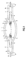
- the high-pressure metal halide lamp of Fig. 1 has a sealed light-transmittent discharge vessel 1, in the Fig. of quartz glass, but alternatively of mono- or polycrystalline ceramic, which has opposite seals 2 and which envelopes a discharge space 3.
- the lamp shown in Fig. 1 is an AC-lamp, but DC-lamps fall within the scope of this invention as well.
- the discharge space has a gas filling comprising rare gas and metal halides.
- Tungsten electrodes 5 are oppositely disposed in the discharge space 3.
- Current leadthrough conductors 6 are located in a respective seal 2 of the discharge vessel 1 and issue from the discharge vessel. In the Fig. the current lead-through conductors are each composed of a metal foil 6a, e.g.
- Electrode rods 7 are connected to a respective one of said leadthrough conductors 6, in the Fig. by welding them to the metal foils 6a, enter the discharge space 3 and carry a respective one of said electrodes 5.
- the gas filling contains metal oxyhalides and is substantially devoid of rare earth metal compounds.
- the electrode rods 7 have a first portion 71 of tungsten adjacent the electrode 5 which merges into a second portion 72 at a location 73 having a temperature in the range of 1900 - 2300 K, particularly 2100 - 2300 K, in the Fig. 2100 K, during operation.
- the second portions 72 of the electrode rods 7 consists of rhenium and are thicker, have a diameter of 1 mm, than the first portions 71, which have a diameter of 0.8 mm.
- the electrodes 5 in the Figure are free end portions of the first electrode rod portions 71.
- the electrode rods 7 have at the first portion 71 a wrapping 74 of tungsten wire adjacent the electrodes 5, to adjust the temperature of the electrodes.
- the lamp of Fig. 1 consumes a power of 200 W.
- the lamp. having a volume of 0.7 cm 3 and an electrode distance of 3 mm, was filled with 0.87 mg Nal, 0.45 mg SnI 2 , 0.76 mg NaBr, 0.21 mg TlBr, 0.17 mg HgI 2 , 2666 Pa O 2 , 44 mg Hg and 10 000 Pa Ar.
- the oxygen reacts to form oxyhalides.
- the electrode rod 7 has a first portion 71 and a wire wrapping 74 of tungsten and a second portion 72 of rhenium/tungsten alloy up to the location 73.
- the electrode rod 7 has a first portion 71 and a wire wrapping 74 of tungsten, a second portion made of rhenium, which portions have a common boundary region at location 73.
- Location 73 extends over a distance X over the electrode rod 7. Over the distance X the temperature lies between 2300 and 1900 K during normal operation of the lamp.
- the location 73 is formed by the boundary region between a core 76 made of rhenium which is enclosed by a mantle 77 made of tungsten.
- the electrode rod 7 has a first portion 71 and a wire wrapping 74 of tungsten, a second portion 72 made of a rhenium/tungsten alloy from locations 73 to 81 and a third portion 80 made of molybdenum.
- the curve W designates the sum of the pressure of tungsten vapor and of the pressures of tungsten compounds in a lamp in dependency of the temperature, whereas the curve Re represents the rhenium vapor pressure at different temperatures.
- the sum of the tungsten pressures is highest at about 1500 K and lowest at about 2250 K. This means that a tungsten surface of 1500 K will loose tungsten by evaporation and by chemical reactions giving volatile products, which will be transported and be deposited at a surface of about 2250 K, or higher due to faster decomposition reactions at higher temperatures, 2300 - 2500 K. These processes are not desired, because they would transport tungsten from a tungsten electrode rod towards the electrode, thereby causing the rod to become thinner and to break.
- the two curves intersect at about 2000 K.
- the temperature of the point of intersection of the curves is the proper temperature of the common boundary at the location 73 of the first 71 and the second electrode rod portions 72. If in the lamp the temperature of said common boundary would be higher than the one shown, the highest rhenium temperature in the lamp would be higher and there would be a higher rhenium evaporation.
- the temperature of the common boundary would be lower, the highest rhenium temperature would be lower and as a consequence the rhenium vapor pressure would be lower, but the tungsten pressures at the boundary would be higher and consequently transport of tungsten from that place to places of higher temperature where the W curve has a minimum would occur.
- the W curve shifts to the right and the two curves intersect at a higher temperature. In a lamp without substantial impurities the curves will intersect at about 1900 K.
Landscapes
- Vessels And Coating Films For Discharge Lamps (AREA)
Abstract
Claims (6)
- Lampe à l'halogénure métallique à haute pression comprenant:caractérisée en ce que le remplissage de gaz contient des oxyhalogénures et est pratiquement dépourvu de composés de métaux des terres rares, les tiges d'électrode (7) présentent une première (71) partie en tungstène voisine de l'électrode (5) qui est fusionnée dans une deuxième partie (72) à un endroit (73) présentant une température située dans la gamme comprise entre 1900 et 2300 K pendant le fonctionnement, la deuxième partie (72) est réalisée en au moins 25 % en poids de rhénium, le reste étant du tungstène et étant fixé à un conducteur de traversée de courant respectif (6).une enceinte à décharge transmettant la lumière scellée (1) présentant des scellements opposés (2) et enveloppant un espace à décharge (3) qui est muni d'un remplissage de gaz comprenant du gaz rare et des halogénures métalliques;des électrodes de tungstène (5) disposées de façon opposée dans l'espace à décharge (3);des conducteurs de traversée de courant (6) situés dans un scellement respectif (2) de l'enceinte à décharge (1) et sortant de l'enceinte à décharge;des tiges d'électrode (7) fixées à un conducteur de traversée de courant respectif desdits conducteurs de traversée de courant (6) entrant dans l'espace à décharge (3) et présentant une électrode respective desdites électrodes (5),
- Lampe à l'halogénure métallique à haute pression selon la revendication 1, caractérisée en ce que l'endroit (73) présente une température située dans la gamme comprise entre 2100 et 2300 K pendant le fonctionnement.
- Lampe à l'halogénure métallique à haute pression selon la revendication 1 ou 2, caractérisée en ce que les deuxièmes parties (72) des tiges d'électrode sont constituées par du rhénium.
- Lampe à l'halogénure métallique à haute pression selon la revendication 3, caractérisée en ce que les deuxièmes parties (72) des tiges d'électrode (7) sont plus épaisses que les premières parties (71).
- Lampe à l'halogénure métallique à haute pression selon la revendication 1,
caractérisée en ce que l'endroit (73) est formé par une région de limite sur laquelle, lors du fonctionnement, la température est située entre 2300 et 1900 K, la deuxième partie (72) de cette région de limite étant enfermée par une enveloppe (77) qui est réalisée essentiellement en tungstène. - Lampe à l'halogénure métallique à haute pression selon la revendication 1, caractérisée en ce que les tiges d'électrode (7) comprennent des première (71), deuxième (72) et troisième parties (80), dont les deuxièmes parties sont fusionnées dans les troisièmes parties aux deuxième endroits (81) présentant une température inférieure à environ 1400 K pendant le fonctionnement de la lampe et dont les troisièmes parties sont fixées à des conducteurs de traversée de courant respectifs (6).
Priority Applications (1)
| Application Number | Priority Date | Filing Date | Title |
|---|---|---|---|
| EP98901459A EP0902964B1 (fr) | 1997-02-24 | 1998-02-16 | Lampe aux halogenures haute pression |
Applications Claiming Priority (4)
| Application Number | Priority Date | Filing Date | Title |
|---|---|---|---|
| EP97200507 | 1997-02-24 | ||
| EP97200507 | 1997-02-24 | ||
| EP98901459A EP0902964B1 (fr) | 1997-02-24 | 1998-02-16 | Lampe aux halogenures haute pression |
| PCT/IB1998/000195 WO1998037571A1 (fr) | 1997-02-24 | 1998-02-16 | Lampe aux halogenures haute pression |
Publications (2)
| Publication Number | Publication Date |
|---|---|
| EP0902964A1 EP0902964A1 (fr) | 1999-03-24 |
| EP0902964B1 true EP0902964B1 (fr) | 2003-09-03 |
Family
ID=8228036
Family Applications (2)
| Application Number | Title | Priority Date | Filing Date |
|---|---|---|---|
| EP98901451A Expired - Lifetime EP0909457B1 (fr) | 1997-02-24 | 1998-02-16 | Lampe aux halogenures haute pression |
| EP98901459A Expired - Lifetime EP0902964B1 (fr) | 1997-02-24 | 1998-02-16 | Lampe aux halogenures haute pression |
Family Applications Before (1)
| Application Number | Title | Priority Date | Filing Date |
|---|---|---|---|
| EP98901451A Expired - Lifetime EP0909457B1 (fr) | 1997-02-24 | 1998-02-16 | Lampe aux halogenures haute pression |
Country Status (6)
| Country | Link |
|---|---|
| US (2) | US6169365B1 (fr) |
| EP (2) | EP0909457B1 (fr) |
| JP (2) | JP2000509893A (fr) |
| CN (2) | CN1146008C (fr) |
| DE (2) | DE69817716T2 (fr) |
| WO (2) | WO1998037570A1 (fr) |
Families Citing this family (36)
| Publication number | Priority date | Publication date | Assignee | Title |
|---|---|---|---|---|
| EP0909457B1 (fr) * | 1997-02-24 | 2003-08-27 | Koninklijke Philips Electronics N.V. | Lampe aux halogenures haute pression |
| TW385479B (en) * | 1998-04-08 | 2000-03-21 | Koninkl Philips Electronics Nv | Metal-halide lamp |
| DE69911735T2 (de) * | 1998-06-30 | 2004-07-29 | Koninklijke Philips Electronics N.V. | Hochdruckentladungslampe |
| DE69915253T2 (de) * | 1998-06-30 | 2005-01-27 | Koninklijke Philips Electronics N.V. | Hochdruckentladungslampe |
| DE29823366U1 (de) * | 1998-08-06 | 1999-07-08 | Patent-Treuhand-Gesellschaft für elektrische Glühlampen mbH, 81543 München | Elektrode für eine Hochdruckentladungslampe mit langer Lebensdauer |
| DE19915920A1 (de) | 1999-04-09 | 2000-10-19 | Heraeus Gmbh W C | Metallisches Bauteil und Entladungslampe |
| JP2005108435A (ja) * | 1999-06-30 | 2005-04-21 | Hamamatsu Photonics Kk | フラッシュランプ |
| US6844679B1 (en) * | 1999-10-18 | 2005-01-18 | Matsushita Electric Industrial Co., Ltd. | Mercury lamp, lamp unit, method for producing mercury lamp and electric lamp |
| DE19957561A1 (de) * | 1999-11-30 | 2001-05-31 | Philips Corp Intellectual Pty | Hochdruckgasentladungslampe |
| AU745886B2 (en) * | 1999-12-20 | 2002-04-11 | Toshiba Lighting & Technology Corporation | A high-pressure metal halide A.C. discharge lamp and a lighting apparatus using the lamp |
| DE10132797A1 (de) * | 2000-07-28 | 2002-05-02 | Patent Treuhand Ges Fuer Elektrische Gluehlampen Mbh | Kurzbogenlampe mit verlängerter Lebensdauer |
| JP3596448B2 (ja) * | 2000-09-08 | 2004-12-02 | ウシオ電機株式会社 | ショートアーク型水銀放電ランプ |
| US6476566B2 (en) | 2000-12-27 | 2002-11-05 | Infocus Systems, Inc. | Method and apparatus for canceling ripple current in a lamp |
| US6815888B2 (en) | 2001-02-14 | 2004-11-09 | Advanced Lighting Technologies, Inc. | Halogen lamps, fill material and methods of dosing halogen lamps |
| KR20030020846A (ko) | 2001-09-04 | 2003-03-10 | 마쯔시다덴기산교 가부시키가이샤 | 고압방전램프 및 그 제조방법 |
| DE10200009A1 (de) * | 2002-01-02 | 2003-07-17 | Philips Intellectual Property | Entladungslampe |
| CN100401457C (zh) * | 2002-01-04 | 2008-07-09 | 皇家飞利浦电子股份有限公司 | 放电灯 |
| US6743831B2 (en) * | 2002-04-23 | 2004-06-01 | Medtronic, Inc. | Implantable medical catheter having reinforced silicone elastomer composition |
| KR20040002563A (ko) * | 2002-06-26 | 2004-01-07 | 마쯔시다덴기산교 가부시키가이샤 | 고압수은램프 및 램프유닛 |
| DE10254969A1 (de) * | 2002-11-26 | 2004-06-03 | Philips Intellectual Property & Standards Gmbh | Hochdruckentladungslampe mit Quecksilberchlorid bei begrenztem Chlorgehalt |
| US7038384B2 (en) * | 2003-01-14 | 2006-05-02 | Matsushita Electric Industrial Co., Ltd. | High pressure discharge lamp, method for producing the same and lamp unit |
| US20050238522A1 (en) * | 2004-04-22 | 2005-10-27 | Rhenium Alloys, Inc. | Binary rhenium alloys |
| US7453212B2 (en) * | 2005-01-31 | 2008-11-18 | Osram Sylvania Inc. | Ceramic discharge vessel having tungsten alloy feedthrough |
| JP2008539332A (ja) * | 2005-04-27 | 2008-11-13 | コーニンクレッカ フィリップス エレクトロニクス エヌ ヴィ | 3質量%より少ないレニウムを含むタングステン合金から製造された電極を有する放電ランプ |
| WO2007005459A2 (fr) * | 2005-06-29 | 2007-01-11 | Albany International Corp. | Fil contenant des microfibres de polyester siliconees |
| US8358070B2 (en) * | 2007-12-06 | 2013-01-22 | General Electric Company | Lanthanide oxide as an oxygen dispenser in a metal halide lamp |
| US8653732B2 (en) | 2007-12-06 | 2014-02-18 | General Electric Company | Ceramic metal halide lamp with oxygen content selected for high lumen maintenance |
| US7737058B2 (en) * | 2008-01-23 | 2010-06-15 | Milliken & Company | Airbag with flame retardant monolithic coating layer |
| US7737059B1 (en) | 2009-02-19 | 2010-06-15 | Milliken & Company | Airbag coating |
| US8134290B2 (en) | 2009-04-30 | 2012-03-13 | Scientific Instrument Services, Inc. | Emission filaments made from a rhenium alloy and method of manufacturing thereof |
| JP5286536B2 (ja) * | 2009-05-25 | 2013-09-11 | Omtl株式会社 | 高圧放電ランプおよび照明装置 |
| CN101660077B (zh) * | 2009-08-12 | 2011-05-25 | 朱惠冲 | 铼钨丝发射材料及用途 |
| DE102009056753A1 (de) * | 2009-12-04 | 2011-06-09 | Heraeus Noblelight Gmbh | Elektrische Hochdruckentladungslampe für kosmetische Hautbehandlung |
| US8497633B2 (en) | 2011-07-20 | 2013-07-30 | General Electric Company | Ceramic metal halide discharge lamp with oxygen content and metallic component |
| DE102011084911A1 (de) * | 2011-10-20 | 2013-04-25 | Osram Gmbh | Quecksilberdampf-kurzbogenlampe für gleichstrombetrieb mit kreisprozess |
| US20140252945A1 (en) * | 2011-10-20 | 2014-09-11 | Osram Gmbh | Mercury vapor short arc lamp for dc operation with circular process |
Family Cites Families (12)
| Publication number | Priority date | Publication date | Assignee | Title |
|---|---|---|---|---|
| US3988629A (en) * | 1974-10-07 | 1976-10-26 | General Electric Company | Thermionic wick electrode for discharge lamps |
| DE3641045A1 (de) * | 1986-12-01 | 1988-06-09 | Patent Treuhand Ges Fuer Elektrische Gluehlampen Mbh | Einseitig gequetschte hochdruckentladungslampe |
| KR910010108B1 (ko) * | 1988-05-27 | 1991-12-16 | 도오시바 라이텍크 가부시기가이샤 | 편봉지형 메탈해라이드 램프 |
| EP0381035B1 (fr) * | 1989-01-31 | 1994-08-03 | Toshiba Lighting & Technology Corporation | Lampe à décharge à vapeur métallique à scellement unique |
| DE4203976A1 (de) * | 1992-02-11 | 1993-08-12 | Patent Treuhand Ges Fuer Elektrische Gluehlampen Mbh | Hochdruckentladungslampe |
| EP0581354B1 (fr) * | 1992-07-13 | 1998-04-29 | Koninklijke Philips Electronics N.V. | Lampe à décharge électrique à haute pression |
| US5461277A (en) * | 1992-07-13 | 1995-10-24 | U.S. Philips Corporation | High-pressure gas discharge lamp having a seal with a cylindrical crack about the electrode rod |
| US5424609A (en) * | 1992-09-08 | 1995-06-13 | U.S. Philips Corporation | High-pressure discharge lamp |
| DE69324790T2 (de) * | 1993-02-05 | 1999-10-21 | Ngk Insulators, Ltd. | Keramisches Entladungsgefäss für Hochdruckentladungslampe und Herstellungsverfahren derselben und damit verbundene Dichtungsmaterialien |
| JPH07114902A (ja) * | 1993-10-19 | 1995-05-02 | Hamamatsu Photonics Kk | メタルハライドランプ |
| WO1995030237A1 (fr) * | 1994-05-03 | 1995-11-09 | Philips Electronics N.V. | Lampe a decharge haute pression |
| EP0909457B1 (fr) * | 1997-02-24 | 2003-08-27 | Koninklijke Philips Electronics N.V. | Lampe aux halogenures haute pression |
-
1998
- 1998-02-16 EP EP98901451A patent/EP0909457B1/fr not_active Expired - Lifetime
- 1998-02-16 US US09/171,058 patent/US6169365B1/en not_active Expired - Fee Related
- 1998-02-16 EP EP98901459A patent/EP0902964B1/fr not_active Expired - Lifetime
- 1998-02-16 DE DE69817716T patent/DE69817716T2/de not_active Expired - Fee Related
- 1998-02-16 WO PCT/IB1998/000187 patent/WO1998037570A1/fr not_active Ceased
- 1998-02-16 DE DE69817493T patent/DE69817493T2/de not_active Expired - Fee Related
- 1998-02-16 CN CNB988001691A patent/CN1146008C/zh not_active Expired - Fee Related
- 1998-02-16 JP JP10529255A patent/JP2000509893A/ja active Pending
- 1998-02-16 CN CNB988001713A patent/CN1146009C/zh not_active Expired - Fee Related
- 1998-02-16 WO PCT/IB1998/000195 patent/WO1998037571A1/fr not_active Ceased
- 1998-02-16 JP JP10529247A patent/JP2000509892A/ja active Pending
- 1998-02-18 US US09/025,368 patent/US6060829A/en not_active Expired - Fee Related
Also Published As
| Publication number | Publication date |
|---|---|
| CN1217816A (zh) | 1999-05-26 |
| EP0909457A1 (fr) | 1999-04-21 |
| WO1998037570A1 (fr) | 1998-08-27 |
| DE69817493T2 (de) | 2004-06-17 |
| JP2000509893A (ja) | 2000-08-02 |
| EP0902964A1 (fr) | 1999-03-24 |
| CN1217815A (zh) | 1999-05-26 |
| US6169365B1 (en) | 2001-01-02 |
| US6060829A (en) | 2000-05-09 |
| DE69817493D1 (de) | 2003-10-02 |
| JP2000509892A (ja) | 2000-08-02 |
| DE69817716D1 (de) | 2003-10-09 |
| CN1146008C (zh) | 2004-04-14 |
| EP0909457B1 (fr) | 2003-08-27 |
| WO1998037571A1 (fr) | 1998-08-27 |
| CN1146009C (zh) | 2004-04-14 |
| DE69817716T2 (de) | 2004-07-15 |
Similar Documents
| Publication | Publication Date | Title |
|---|---|---|
| EP0902964B1 (fr) | Lampe aux halogenures haute pression | |
| JP3654929B2 (ja) | 高圧放電ランプ | |
| JPS6343867B2 (fr) | ||
| US5212424A (en) | Metal halide discharge lamp containing a sodium getter | |
| GB1580991A (en) | High pressure gas discharge light source with metal halide additive | |
| EP0876679B1 (fr) | Lampe a decharge et a haute pression | |
| US3900750A (en) | Metal halide discharge lamp having heat absorbing coating | |
| CA2099393C (fr) | Lampe aux halogenures | |
| US6617790B2 (en) | Metal halide lamp with ceramic discharge vessel | |
| US5729091A (en) | Metal halide discharge lamp | |
| JP2001126659A (ja) | 水銀短アーク灯 | |
| US4798995A (en) | Metal halide lamp containing halide composition to control arc tube performance | |
| JP3995053B1 (ja) | Hidランプ | |
| JP4022302B2 (ja) | メタルハライド放電ランプおよび照明装置 | |
| JPH04223037A (ja) | 高圧放電ランプ | |
| CA1280150C (fr) | Lampe a halogenure de metal contenant un compose a halogenure pour controler la performance du tube a decharge | |
| JP2014531116A (ja) | サイクルを有する、直流動作用の水銀蒸気ショートアークランプ | |
| JPH0845471A (ja) | メタルハライドランプ | |
| GB1591617A (en) | High pressure electric discharge lamps | |
| WO2007107889A1 (fr) | Dispositif a decharge de haute intensite ayant un metal a faible energie d'extraction dans l'espace de decharge | |
| JPH11135070A (ja) | セラミック製放電ランプ | |
| JP2001093474A (ja) | メタルハライドランプ | |
| GB1600269A (en) | High pressure electric discharge lamps | |
| JPH09320528A (ja) | メタルハライドランプ |
Legal Events
| Date | Code | Title | Description |
|---|---|---|---|
| PUAI | Public reference made under article 153(3) epc to a published international application that has entered the european phase |
Free format text: ORIGINAL CODE: 0009012 |
|
| AK | Designated contracting states |
Kind code of ref document: A1 Designated state(s): DE ES FR GB IT |
|
| 17P | Request for examination filed |
Effective date: 19990301 |
|
| RAP1 | Party data changed (applicant data changed or rights of an application transferred) |
Owner name: PHILIPS CORPORATE INTELLECTUAL PROPERTY GMBH Owner name: KONINKLIJKE PHILIPS ELECTRONICS N.V. |
|
| RAP1 | Party data changed (applicant data changed or rights of an application transferred) |
Owner name: PHILIPS CORPORATE INTELLECTUAL PROPERTY GMBH Owner name: KONINKLIJKE PHILIPS ELECTRONICS N.V. |
|
| GRAH | Despatch of communication of intention to grant a patent |
Free format text: ORIGINAL CODE: EPIDOS IGRA |
|
| RAP1 | Party data changed (applicant data changed or rights of an application transferred) |
Owner name: PHILIPS INTELLECTUAL PROPERTY & STANDARDS GMBH Owner name: KONINKLIJKE PHILIPS ELECTRONICS N.V. |
|
| GRAS | Grant fee paid |
Free format text: ORIGINAL CODE: EPIDOSNIGR3 |
|
| GRAA | (expected) grant |
Free format text: ORIGINAL CODE: 0009210 |
|
| AK | Designated contracting states |
Kind code of ref document: B1 Designated state(s): DE ES FR GB IT |
|
| PG25 | Lapsed in a contracting state [announced via postgrant information from national office to epo] |
Ref country code: IT Free format text: LAPSE BECAUSE OF FAILURE TO SUBMIT A TRANSLATION OF THE DESCRIPTION OR TO PAY THE FEE WITHIN THE PRESCRIBED TIME-LIMIT;WARNING: LAPSES OF ITALIAN PATENTS WITH EFFECTIVE DATE BEFORE 2007 MAY HAVE OCCURRED AT ANY TIME BEFORE 2007. THE CORRECT EFFECTIVE DATE MAY BE DIFFERENT FROM THE ONE RECORDED. Effective date: 20030903 |
|
| REG | Reference to a national code |
Ref country code: GB Ref legal event code: FG4D |
|
| REF | Corresponds to: |
Ref document number: 69817716 Country of ref document: DE Date of ref document: 20031009 Kind code of ref document: P |
|
| PG25 | Lapsed in a contracting state [announced via postgrant information from national office to epo] |
Ref country code: ES Free format text: LAPSE BECAUSE OF FAILURE TO SUBMIT A TRANSLATION OF THE DESCRIPTION OR TO PAY THE FEE WITHIN THE PRESCRIBED TIME-LIMIT Effective date: 20031214 |
|
| PGFP | Annual fee paid to national office [announced via postgrant information from national office to epo] |
Ref country code: FR Payment date: 20040226 Year of fee payment: 7 |
|
| PGFP | Annual fee paid to national office [announced via postgrant information from national office to epo] |
Ref country code: GB Payment date: 20040227 Year of fee payment: 7 |
|
| PGFP | Annual fee paid to national office [announced via postgrant information from national office to epo] |
Ref country code: DE Payment date: 20040415 Year of fee payment: 7 |
|
| ET | Fr: translation filed | ||
| PLBE | No opposition filed within time limit |
Free format text: ORIGINAL CODE: 0009261 |
|
| STAA | Information on the status of an ep patent application or granted ep patent |
Free format text: STATUS: NO OPPOSITION FILED WITHIN TIME LIMIT |
|
| 26N | No opposition filed |
Effective date: 20040604 |
|
| PG25 | Lapsed in a contracting state [announced via postgrant information from national office to epo] |
Ref country code: GB Free format text: LAPSE BECAUSE OF NON-PAYMENT OF DUE FEES Effective date: 20050216 |
|
| PG25 | Lapsed in a contracting state [announced via postgrant information from national office to epo] |
Ref country code: DE Free format text: LAPSE BECAUSE OF NON-PAYMENT OF DUE FEES Effective date: 20050901 |
|
| GBPC | Gb: european patent ceased through non-payment of renewal fee |
Effective date: 20050216 |
|
| PG25 | Lapsed in a contracting state [announced via postgrant information from national office to epo] |
Ref country code: FR Free format text: LAPSE BECAUSE OF NON-PAYMENT OF DUE FEES Effective date: 20051031 |
|
| REG | Reference to a national code |
Ref country code: FR Ref legal event code: ST Effective date: 20051031 |