EP0902357A2 - Procédé de sortie et dispositif - Google Patents
Procédé de sortie et dispositif Download PDFInfo
- Publication number
- EP0902357A2 EP0902357A2 EP98203328A EP98203328A EP0902357A2 EP 0902357 A2 EP0902357 A2 EP 0902357A2 EP 98203328 A EP98203328 A EP 98203328A EP 98203328 A EP98203328 A EP 98203328A EP 0902357 A2 EP0902357 A2 EP 0902357A2
- Authority
- EP
- European Patent Office
- Prior art keywords
- data
- interface
- receiving
- selecting
- accordance
- Prior art date
- Legal status (The legal status is an assumption and is not a legal conclusion. Google has not performed a legal analysis and makes no representation as to the accuracy of the status listed.)
- Granted
Links
Images


Classifications
-
- G—PHYSICS
- G06—COMPUTING; CALCULATING OR COUNTING
- G06F—ELECTRIC DIGITAL DATA PROCESSING
- G06F3/00—Input arrangements for transferring data to be processed into a form capable of being handled by the computer; Output arrangements for transferring data from processing unit to output unit, e.g. interface arrangements
- G06F3/12—Digital output to print unit, e.g. line printer, chain printer
- G06F3/1293—Printer information exchange with computer
- G06F3/1295—Buffering means
-
- G—PHYSICS
- G06—COMPUTING; CALCULATING OR COUNTING
- G06F—ELECTRIC DIGITAL DATA PROCESSING
- G06F3/00—Input arrangements for transferring data to be processed into a form capable of being handled by the computer; Output arrangements for transferring data from processing unit to output unit, e.g. interface arrangements
- G06F3/12—Digital output to print unit, e.g. line printer, chain printer
- G06F3/1201—Dedicated interfaces to print systems
- G06F3/1202—Dedicated interfaces to print systems specifically adapted to achieve a particular effect
- G06F3/121—Facilitating exception or error detection and recovery, e.g. fault, media or consumables depleted
-
- G—PHYSICS
- G06—COMPUTING; CALCULATING OR COUNTING
- G06F—ELECTRIC DIGITAL DATA PROCESSING
- G06F3/00—Input arrangements for transferring data to be processed into a form capable of being handled by the computer; Output arrangements for transferring data from processing unit to output unit, e.g. interface arrangements
- G06F3/12—Digital output to print unit, e.g. line printer, chain printer
- G06F3/1201—Dedicated interfaces to print systems
- G06F3/1223—Dedicated interfaces to print systems specifically adapted to use a particular technique
- G06F3/1229—Printer resources management or printer maintenance, e.g. device status, power levels
- G06F3/1234—Errors handling and recovery, e.g. reprinting
-
- G—PHYSICS
- G06—COMPUTING; CALCULATING OR COUNTING
- G06F—ELECTRIC DIGITAL DATA PROCESSING
- G06F3/00—Input arrangements for transferring data to be processed into a form capable of being handled by the computer; Output arrangements for transferring data from processing unit to output unit, e.g. interface arrangements
- G06F3/12—Digital output to print unit, e.g. line printer, chain printer
- G06F3/1201—Dedicated interfaces to print systems
- G06F3/1223—Dedicated interfaces to print systems specifically adapted to use a particular technique
- G06F3/1236—Connection management
-
- G—PHYSICS
- G06—COMPUTING; CALCULATING OR COUNTING
- G06F—ELECTRIC DIGITAL DATA PROCESSING
- G06F3/00—Input arrangements for transferring data to be processed into a form capable of being handled by the computer; Output arrangements for transferring data from processing unit to output unit, e.g. interface arrangements
- G06F3/12—Digital output to print unit, e.g. line printer, chain printer
- G06F3/1201—Dedicated interfaces to print systems
- G06F3/1278—Dedicated interfaces to print systems specifically adapted to adopt a particular infrastructure
- G06F3/1284—Local printer device
Definitions
- the present invention relates to an output method or an apparatus which uses an interface such as an RS-232C, SCS1 or parallel interface such as that produced by the Centronics company.
- printing devices using several interfaces, which can select the interface through which first data is received. For that reason, if the speed of transferring data through the selected interface is slow, the time necessary for receiving the data is long. Moreover, it is necessary for the device to interpret the received data and therefore, processing the data to be received through the unselected interfaces is still more delayed. Getting back to the device that selects the interface with which the first data is received as stated above. If the processing of the data is interrupted, such as, for example, at the middle of a page to be printed, processing the data to be received by the unselected interface is still more delayed. There are some devices with several interfaces including a two-way interface which can automatically change from one interface to another. But if one interface is selected, these printing devices can get and interpret data only through the selected interface.
- error recovery is carried out for a selected interface or for all interfaces regardless of the reason for the error.
- the present invention has been made in consideration of the above situations, and has as one of its objects, to provide an output method and apparatus capable of controlling a size of receiving buffers when receiving data through each interface. Another object is to provide an output method and apparatus capable of changing from one interface to another in accordance with the condition of the data being received.
- Another object of the present invention is to provide an output method and apparatus capable of assigning an adequate amount of the receiving buffer to each interface by controlling the size of the receiving buffers in accordance with the condition of the selected interfaces.
- Another object of the present invention is to provide an output method and apparatus capable of selecting an effective interface for use by changing from one interface to another in accordance with a result of monitoring the condition of the receiving buffers.
- Another object of the present invention is to provide an output method and apparatus capable of selecting a usable interface by changing from one interface to another in accordance with the result of detecting the end of data at each interface.
- Another object of the present invention is to provide an output method and apparatus capable of informing the condition of each interface by transferring a predetermined status signal through the two-way interface regardless of the condition of the selected interface.
- Another object of the present invention is to provide an output method and apparatus capable of limiting the interface to carry out the process of error recovery in accordance with the condition of error occurring while the selection of interface remains the same.
- Another object of the present invention is to provide an output method and apparatus capable of restricting useless data processing after a transmitting error has occurred a few times and disregarding the data from the interface relating to the error until a time-out signal has occurred, by monitoring the condition of error occurring.
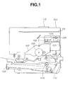
- Fig. 1 is a cross-sectional view of a recording apparatus, such as a laser beam printer.
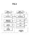
- Fig. 2 is a block diagram showing controlling construction of a printing apparatus common to all embodiments.
- Fig. 3 is a schematic block diagram of a condition of a memory map of RAM.
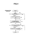
- Fig. 4 is a flow chart showing one example of data interruption processing according to the first embodiment.
- Fig. 5 is a flow chart showing one embodiment of a first printing process.
- Fig. 6 is a block diagram showing a construction of a controller according to a second embodiment of a printing apparatus.
- Fig. 7 is a schematic block diagram of a condition of a memory map of RAM in Fig. 6.
- Fig. 8 is a flow chart showing a second embodiment of a data interruption receiving process of a printing apparatus.
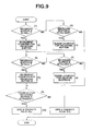
- Fig. 9 is a flow chart for determining an interface to take priority in a printing apparatus.
- Fig. 10 is a flow chart showing a data interrupt receiving process of a printing apparatus according to a third embodiment.
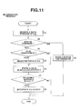
- Fig. 11 is a flow chart showing a fourth embodiment of a data interrupt receiving process of a printing apparatus.
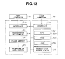
- Fig. 12 is a block diagram showing a construction of a controller for a printing apparatus according to a fifth embodiment.
- Fig. 13 is a flow chart showing a data interruption receiving process of a printing apparatus according to the fifth embodiment.
- Fig. 14 is a flow chart showing a first error process of a printing apparatus.
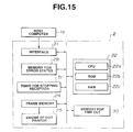
- Fig. 15 is a block diagram of a printing apparatus according to the sixth embodiment.
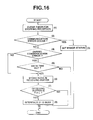
- Fig. 16 is a flow chart showing a data interruption receiving process of a printing apparatus according to the sixth embodiment.
- Fig. 17 is a flow chart showing an interruption process by a timer control of a printing apparatus according to the sixth embodiment.
- Fig. 18 is a perspective view showing the internal structure of an ink jet printer to which the present invention can be applied.
- Fig. 19 is a block diagram of a control circuit of the ink-jet printer shown in Fig. 18.
- Fig. 1 is a cross-sectional view of a recording apparatus, such as a laser beam printer, in which the character processing method of the present invention is applicable.
- a main body 100 (printer) of the apparatus receives and stores print information (character codes etc.), form information and macro instructions supplied from an external host computer, generates character patterns (to be generated by the character pattern process of the present invention), forms patterns, and forms an image on a recording sheet constituting the recording medium.
- an operation panel - including switches and LED indicators for various operations and a printer control unit 101 for controlling the entire printer 100 and analyzing the character information supplied from the host computer.
- the printer control unit 101 converts the character information into a video signal of corresponding character patterns for supply to a laser driver 102, which drives a semiconductor laser 103 and on-off switches the laser beam 104 emitted from the semiconductor laser 103 according to the input video signal.
- the laser beam 104 is laterally deflected by a rotary polygon mirror 105 to scan an electrostatic drum 106, thereby forming an electrostatic latent image of a character pattern thereon.
- the latent image is developed into a visible image by a developing unit 107 positioned around the electrostatic drum 106, and is transferred onto the recording sheet, which is composed of a cut sheet contained in a cassette 108 mounted on the main body 100 and supplied therefrom by a feed roller 109 and transport rollers 110 and 111 to the electrostatic drum 106.
- the image processing apparatus of each embodiment described above exemplifies a laser beam printer.
- the present invention is not limited to this.
- the present invention is equally applied to an ink-jet printer to be described later.
- Fig. 18 is a perspective view of an ink-jet recording apparatus IJRA to which the present invention can be applied.
- a carriage HC engages with a helical groove 5005 of a lead screw 5004 rotated interlockingly with normal/reverse rotation of a drive motor 5013 through driving force transmission gears 5011 and 5009 having a pin (not shown) and can be reciprocated in directions indicated by arrows a and b.
- An ink-jet cartridge IJC is mounted on the carriage HC.
- a paper press plate 5002 presses the paper in the carriage movement direction through a platen 5000.
- Photocouplers 5007 and 5008 are home position detecting means for detecting the presence of a lever 5006 of the carriage within this range to switch the rotational direction of the motor 5013.
- a member 5016 supports a cap member 5022 for capping the front surface of a recording head.
- a suction device 5015 draws the ink from the cap to recover the recording head through an opening 5023 in the cap.
- a cleaning blade 5017 is moved back and forth by a member 5019, and the cleaning blade 5017 and the member 5019 are supported on a main body support plate 5018. The blade need not have this form, but can be replaced with a known cleaning blade.
- a lever 5021 starts suction to recover the recording head.
- the lever 5012 is moved together with movement of a cam 5020 engaged with the carriage.
- the driving force from the driving motor is controlled by a known transmitting means such as clutch switching.
- Capping, cleaning and suction recovery are performed by desired processes at the corresponding positions in accordance with the behavior of the lead screw 5004 when the carriage reaches the home position. If desired operations are performed at known timings, any scheme can be employed in this embodiment.
- a control circuit includes an interface 1700 for inputting a recording signal, an MPU 1701, a program ROM 1702 for storing control programs executed by the MPU 1701, a dynamic RAM 1703 for storing various data (e.g., the recording signal and recording data supplied to the head), a gate array 1704 for controlling and supplying the recording data to a recording head 1708 and performing transfer control of data between the interface 1700, the MPU 1701, and the RAM 1703, a carriage motor 1710 for moving the recording head 1708, a paperfeed motor 1709 for conveying a recording sheet, a head driver 1705 for driving the head, and motor drivers 1706 and 1707 for driving the paperfeed motor 1709 and the carriage motor 1710, respectively.
- a recording signal is input to the interface 1700, a recording signal is converted into print recording data by the gate array 1704 and the MPU 1701.
- the motor drivers 1706 and 1707 are driven to drive the recording head in accordance with the recording data supplied to the head driver 1705, thereby printing the recording information.
- the present invention is applicable to the ink-jet printer in addition to the laser beam printer.
- Fig. 2 is a block diagram showing a construction of a controller of a printing apparatus.
- 1a, 1b are host computers. 2 is a body of the printing apparatus. Each of the host computers 1a and 1b sends data such as print data to a printing apparatus. Each of the interfaces 21a and 21b can receive data from the host computers 1a and 1b.
- Controller 22 controls the entire printing apparatus.
- the controller consists of a CPU 22a, ROM 22b which stores a program of process and outline font data, and so on, and also consists of a RAM 22c which includes receiving buffers and a work area which enables the CPU 22a to execute the program. This work area of the RAM 22c stores information which defines the size of each buffer.
- Memory 23 stores information for the interface presently selected.
- Frame memory 24 is capable of storing bit map data for one page.
- the bit map data which are stored in the frame memory 24 are printed by dot printer engine 25.
- the CPU 22a executes a process in accordance with a program which is stored in ROM 22b. This process determines the size of each receiving buffer (a part of area of RAM 22c) corresponding to each interface. In this embodiment, the CPU 22a exercises an ensuring process, in accordance with a program which is stored in ROM 22b, to ensure the size of the receiving buffer which has been determined by the ROM 22b..
- Taking means (in this embodiment, the CPU 22a executes the taking process in accordance with a program stored in ROM 22b) takes data through each interface to be stored in the determined receiving buffer.
- the printing apparatus can have an adequate size of receiving buffer correspond to each interface.
- Fig. 3 is a schematic block diagram of a condition of a memory map of RAM 22c.
- data from the host computer la are sequentially stored in the receiving buffer A of the RAM 22c through the interface 21a.
- Data from the host computer 1b are sequentially stored in the receiving buffer B of the RAM 22c through the interface 21b.
- the CPU 22a controls the following steps. The data which are not processed in the receiving buffer are read and transferred to the frame memory 24 as image data or the font patterns that correspond to the data as character data are transferred and finally printed.
- the selected receiving buffer is larger than the other one (the non-selected buffer is smaller than the one in the prior art).
- host computers la and 1b can simultaneously send data to the printing apparatus and the printing apparatus can give priority to the selected interface having the smaller area of RAM 22c by varying the size of the receiving buffer.
- the CPU 22a carries out the program described in Fig. 4 as a flow chart stored in the ROM 22b.
- Fig. 4 is a flow chart showing one example of data interruption processing according to the first embodiment.
- (1) ⁇ (5) show each step of the flowchart.
- an interrupt signal is supplied to the interface 21a.
- the CPU 22a performs the process according to the flow chart of Fig. 4.
- step (1) the CPU 22a judges whether an interface can change one to another at present. If YES in step (1), the flow advances to step (2) and the CPU 22a selects interface 21a and stores the information from selected interface 21a in selected interface memory 23. The CPU 22a then expands the receiving buffer A in the RAM 22c (reduces the receiving buffer B). After that, the flow advances to step (3).
- step (3) the CPU 22a takes data through the interface 21a and stores the data in the receiving buffer A in the RAM 22c.
- step (4) the CPU 22a determines whether the receiving buffer A is full. If YES in step (4), the CPU 22a executes a busy process and the program flow ends. CPU 22a performs the same procedure if interface 21b is selected.
- Fig. 5 is a flow chart showing one embodiment of the first printing process.
- (1) ⁇ (10) show each step in the process.
- step (1) the CPU 22a determines which interface is selected at present. If the interface 21a is selected, the CPU 22a takes data from the receiving buffer A (Step(2)). If the interface 21b is selected, the CPU 22a takes data from the receiving buffer B (step (3)).
- step (4) the CPU 22a determines whether the data which is taken is character data. If YES in step (4), the CPU 22a determines in step (6) whether a character pattern which corresponds to the data exists in the font cache area in the RAM 22c. If NO in step(6), the process proceeds to step (7) in which a font pattern is made and registered in the font cache area in RAM 22c. If YES in step(6), the process proceeds directly to step (8). In step (8), the font pattern is stored in frame memory 24 and the flow proceeds to step (9). If NO in step (4), the CPU 22a executes a control process in accordance with the data, and the flow advances to step (9).
- step 9 the CPU 22a determines whether data for 1 page are stored in the frame memory 24.
- step 9 the CPU 22a transfers the data stored in the frame memory 24 to the engine of the dot printer 25 and prints. The flow then returns to step (1) in Fig. 5. If NO in step 9, the flow returns to step (1) directly.
- the printing apparatus can give a priority to the selected interface with a little amount of RAM for receiving data.
- the printing apparatus with two interfaces is described. But in application the number of interfaces is not limited.
- the CPU 22a can ensure the necessary receiving buffer in accordance with the number of interfaces.
- the page printer prints data after preparing data for 1 page.
- this invention can apply a line printer or a serial printer which executes a printing process line by line such as an ink jet printer.
- Fig. 6 is a block diagram showing a construction of a controller according to a second embodiment of a printing apparatus. Symbols are the same as the ones used in Fig. 2.
- 26 is a memory for storing information indicating which interface has priority at present.
- 27 is a counter for determining whether the receiving buffer A which corresponds to the interface 21a is full or not.
- 28 is a counter for determining whether the receiving buffer B which corresponds to the interface 21b is full or not. These counters count while the receiving buffers are full.
- CPU 22a changes between interface 21a and 21b in accordance with the result of monitoring the counters 27 and 28 (in this embodiment, which means are functions of the CPU 22a). So the printing apparatus can always select an effective interface for use.
- CPU 22a can change between interface 21a and 21b in accordance with a result of detecting means which is for detecting an end of data at each interface. So the printing apparatus can always select a usable interface speedily. This embodiment will be further described with reference to Fig. 7.
- Fig. 7 is a schematic block diagram of a condition of memory map of RAM 22c in Fig. 6.
- data transferred from the host computer la through the interface 21a are sequentially stored in the receiving buffer A.
- Data transferred from the host computer 1b through the interface 21b are sequentially stored in the receiving buffer B.
- the CPU 22a reads data which are not processed in the receiving buffer and stores the data in the frame memory 24 as image data or transfers font patterns which correspond to the data to the frame memory 24 and finally the data are printed.
- the CPU 22a ensures two receiving buffers corresponding to each interface 21a and 21b. So, host computers la and 1b can transfer data to the printing apparatus simultaneously.
- the CPU 22a in the controller 22 carries out the program described in Fig. 8 as a flow chart which is stored in ROM 22b.
- Fig. 8 is a flow chart showing a data interruption receiving process according to second embodiment of a printing apparatus. (1) ⁇ (7) in Fig. 8 show each of the steps of the process.
- step (1) in Fig. 8 the CPU 22a takes data through the interface 21a and determines in step (2) whether the interface 21a is given priority. (The process for determining priority is discussed below.) If yes in step (2), the flow advances to step (3). In step (3), the CPU 22a determines whether the interface is changeable at present.
- step (4) the CPU 22a selects the interface 21a and stores information which shows that the interface 21a is selected in the memory 23.
- step (3) If NO in step (3) or if NO in step (2), the flow advances to step (5) directly.
- step (5) the CPU 22a stores the data which is taken in step (1) in the receiving buffer A of the RAM 22c.
- step (6) the CPU 22a determines whether the receiving buffer A is full by referring to counter 27. If YES in step (6), the CPU 22a exercises a busy process and other processes in step (7). A description of the printing process is omitted.
- Fig. 9 is a flow chart for determining an interface to take priority in the printing apparatus.
- (1) ⁇ (11) show each of the steps in the process.
- step (1) the CPU 22a determines whether the receiving buffer A is full. If YES, in step (2) the counter 27 (Fig. 6) for the receiving buffer A counts up. This is for timing how long it is that the full condition exists. If NO, in step (3) the CPU 22a determines if receiving buffer A is vacant. If YES, the CPU 22a clears counter 27 in step (4) and proceeds to step (5). If NO in step (3), the process proceeds directly to step (5). In step (5), the CPU 22a determines whether the receiving buffer B is full. If YES in step (5), the counter 28 for the receiving buffer B is incremented If NO in step (5), the CPU 22a determines whether the receiving buffer B is vacant in step (7).
- step (7) the CPU 22a clears counter 28 in step (8).
- step (9) the CPU 22a compares the numbers in counter 27 and counter 28. If the number in counter 27 is larger than the number in counter 28, the CPU 22a stores in memory 26 information indicating that interface 21a is an interface to be given priority, in step (10). The process ends and the CPU 22a executes another process.
- the CPU 22a stores in memory 26 information indicating that the interface 21b is an interface to be given priority, in step (11). The process ends and the CPU 22a executes another process.
- the printing apparatus can receive data efficiently from a large number computers.
- a printing apparatus with two interfaces is not limited.
- the CPU 22a can ensure a receiving buffer in accordance with the number of interfaces.
- a page printer which prints data after preparing data for 1 page is described.
- this invention can be applied to a line printer or a serial printer which executes a printing process line by line such as an ink jet printer described in Fig. 18.
- the CPU 22a determines the condition of utility of the receiving buffer in accordance with the time in which the receiving buffer is full. However, the CPU 22a may determine the condition of utility by counting the number of data to be read in the receiving buffer.
- Fig. 10 is a flow chart showing a data interrupt receiving process of a printing apparatus according to the third embodiment.
- the CPU 22a receives data through the interface 21a.
- the CPU 22a determines if the data is a form-feed (ff).
- step (2) the CPU 22a determines whether the interface can be changed from one to another. If YES in step (3), the CPU 22a selects interface 21a in step (4) and stores information indicating that interface 21a is selected, in memory 23. The flow then advances to step (5).
- step (2) If NO in step (2), the flow advances to step (5) directly.
- step (5) the CPU 22a stores the received data in the receiving buffer A of the RAM 22c. The CPU 22a then determines whether the receiving buffer A is full in step (6).
- step (6) If YES in step (6), the CPU 22a executes the busy process and other printing processes in step (7). A description of the printing process is omitted.
- the CPU 22a determines the end of data in accordance with the form feed code. However, the CPU 22a may determine the end of data by recognizing that a printing language has changed. (The CPU 22a can distinguish one language from another by storing a specific code for each language.)
- the CPU 22a in spite of a selection condition, can transfer a predetermined status through the two-way interface. So the printing apparatus can inform the condition of each interface in spite of the selection condition.
- Fig. 11 is a flow chart showing a data interrupt receiving process according to a fourth embodiment of a printing apparatus according to the present invention.
- (1) ⁇ (8) show each step of the process.
- step (1) the CPU 22a receives data through the interface 21a.
- step (2) the CPU 22a determines whether the data is a status request command. If YES in step (2), the flow advances to step (3), the CPU 22a makes a status of the printing apparatus and the CPU 22a transfers the status from the interface 21a and executes another process. If NO in step (2), the CPU 22a determines in step (4) whether the interface is changeable. (e.g., whether information is presently being received through the selected interface.) If NO in step (4), the flow advances to step (6) directly. If YES in step (4), the CPU 22a selects interface 21a and stores information indicating that the interface 21a is selected, in memory 23. The flow then advances to step (6).
- step (6) the CPU 22a stores the received data in receiving buffer A in the RAM 22c, and the CPU 22a determines whether the receiving buffer A is full in step (7). If YES in step (7), the CPU 22a executes a busy process and other processes. A description of the printing process is omitted.
- the CPU 22a executes the process in accordance with the status request command, regardless of the condition of the host computers selection. Each interface is ensured a receiving buffer in this embodiment. However, the CPU 22a can interpret the data with the status request command with one or no receiving buffer through data can be received through one interface at once.
- the CPU 22a does not change from one interface to another and does not store a command in the receiving buffer in this embodiment but the CPU 22a can execute the process as like for the ordinary data.
- Fig. 12 is a block diagram showing a construction of a controller of a printing apparatus according to a fifth embodiment.
- Fig. 12 is a memory for error status which stores an error condition.
- a control means controls an interface which relates to an error to be changed (This control is executed by the CPU 22a's function) in accordance with a result of monitoring an error condition.
- the CPU 22a can restrict the interface relating to an error process in this printing device.
- Data from the host computer la are serially stored in the receiving buffer A of the RAM 22c through the interface 21a and data from the host computer 1b are serially stored in the receiving buffer B of the RAM 22c through the interface 21b.
- the CPU 22a reads data which is to be processed sequentially.
- the CPU 22a stores the data in the frame memory 24 directly or stores a font pattern corresponding to the data in the frame memory 24, and finally a print process is executed.
- the CPU 22a ensures that a receiving buffer corresponds to each interface, so that the host computers la and 1b can transfer data simultaneously.
- Fig. 13 is a flow chart showing a data interruption receiving process of a printing apparatus according to the fifth embodiment. (1) ⁇ (7) show each step of the process.
- step (1) the CPU 22a determines whether a communication error has occurred in the interruption reception.
- step (1) the CPU 22a stores error information in an error status memory 29 and the process is finished.
- step (1) the CPU 22a determines whether the interface is changeable in step (3). If YES in step (3), the CPU 22a selects the interface 21a and the CPU 22a stores information indicating that the interface 21a is selected, in the memory 23.
- step (3) the flow advances to step (5) directly.
- the CPU 22a receives data through the interface 21a and stores the data in receiving buffer A in the RAM 22c. The CPU 22a then determines whether the receiving buffer A is full in step (6).
- step (6) the CPU 22a executes a busy process and the process is finished.
- CPU 22a performs the same process for interface 21b.
- Fig. 14 is a flow chart showing a first error recovering process of a printing apparatus.
- (1) ⁇ (4) show each of the steps of the process.
- the error recovery process includes a process of deciding which interface is in error and informing a user accordingly (CPU 22a performs these functions.)
- the CPU 22a determines whether an error condition is occurring in the printing apparatus in accordance with the memory for error status.
- step (1) the process is finished. If YES, in step (2) the CPU 22a determines whether the error is due to a communication error.
- step (2) the CPU 22a executes an error process (produces busy signals) only for the interface which relates to the error.
- step (2) (for example: if the error has occurred because a cover is left opened), the CPU 22a executes in step (4) an error process for both of the interfaces because the data through all interfaces should be stopped and the process is finished.
- the CPU 22a changes the interface in accordance with a kind of error. Accordingly, the host computers can continue transferring the data through the interfaces which do not relate to the error.
- the CPU 22a ensures that each receiving buffer correspond to each interface. But the CPU 22a can proceed for an error in the same way with one or no receiving buffer.
- Fig. 15 is a block diagram of a printing apparatus according to the sixth embodiment.
- 30 is a memory for time out information relating to the data transmitting.
- 31 is a timer for counting a stopping time of data transmission.
- Data skip means (this function is executed by CPU 22a in this embodiment) skips data in this printing apparatus.
- the data are transferred through the interface which has a transmitting error detected by a monitoring means (CPU 22a).
- the skip continues until a generating means (the timer for stopping reception 31) generates a time out signal by measuring a time of transferring data through the interface. Accordingly, the CPU 22a can restrict waste process for the data after occurrence of a transferring error.
- the data from the host computer la are sequentially stored in the receiving buffer A of the RAM 22c through the interface 21 in the sixth embodiment.
- a host computer 1b that sequentially stores data in the receiving buffer B of RAM 22c.
- the CPU 22a reads the data which are to be processed and stores the data in the frame memory 24 as image data or stores font patterns in the frame memory corresponding to the data. Finally the printing process is executed.
- Fig. 16 is a flow chart showing a data interruption receiving process of a printing apparatus according to the sixth embodiment. (1) ⁇ (8) show each step.
- the CPU 22a clears the timer for stopping reception 31 in step (1).
- the CPU 22a determines whether a communication error has occurred.
- step (3) If YES in step (2), the CPU 22a stores in step (3) information indicating that a communication error has occurred, in the memory for error status 29, and the process is finished. Due to this step, the information stored in the memory for time out shows that time out has not occurred.
- step (2) the CPU 22a determines in step (4) whether the skipping data continues in accordance with the information stored in the error status memory 29. If YES in step (4), the CPU 22a determines whether the data time out has occurred in accordance with the information stored in the memory for data time out.
- step (5) If NO in step (5), the process is finished.
- step (4) If NO in step (4) or YES in step (5), the CPU 22a takes data from the interface 21 and stores it in the receiving buffer in RAM 22c in step (6).
- step (7) the CPU 22a determines whether the receiving buffer is full.
- step (7) the CPU 22a executes a busy process in step (8) and the process is finished.
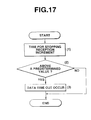
- Fig. 17 is a flow chart showing an interruption process by a timer control of a printing apparatus according to the sixth embodiment.
- (1) ⁇ (3) show each of the steps of the process.
- step (1) the timer for stopping reception 31 is incremented.
- step (2) the CPU 22a determines whether the value of the timer exceeds a predetermined value.
- step (3) the CPU 22a stores information indicating that a data time out has occurred and the process is finished.
- the CPU 22a executes reading processes from the receiving buffer, executes the data interpreting process, executes the storing process in the frame memory 24 and executes the printing process by the dot printer engine in accordance with the data from the host computer la apart from the interrupting process showed in Figs. 16 and 17.
- the CPU 22a skips data from a beginning of the occurrence of the transferring error to before the occurrence of the data time out. Accordingly, the CPU 22a can omit a waste output.
- the CPU 22a clears the time out information when the transferring error occurs in step (3) in Fig. 16.
- the CPU 22a can clear the time out information at the end of skipping data regardless of the occurrence of the transferring error.
- the first embodiment can provide an output method and apparatus capable of assigning adequate amount of receiving buffer to each interface by controlling the size of receiving buffers in accordance with the condition of selected interfaces.
- the second embodiment can provide an output method and apparatus capable of selecting an effective interface for use by controlling to change from one interface to another in accordance with the result of monitoring the condition of the receiving buffers.
- the third embodiment can provide an output method and apparatus capable of selecting a usable interface by controlling to change from one interface to another in accordance with the result of detecting the end of data at each interface.
- the fourth embodiment can provide an output method an apparatus capable of informing the condition of each interface by transferring a predetermined status signal through the two-way interface regardless of the condition of selecting interface.
- the fifth embodiment can provide an output method and apparatus capable of limiting the interface to carry out the process of error recovery in accordance with the condition of error occurring, while the selection of interface remains the same.
- the sixth embodiment can provide an output method and apparatus capable of restricting useless data processing after a transmitting error has occurred a few times by disregarding the data from the interface relating to an error until a time-out signal has occurred, by monitoring the condition of error occurring.
Landscapes
- Engineering & Computer Science (AREA)
- Theoretical Computer Science (AREA)
- Human Computer Interaction (AREA)
- Physics & Mathematics (AREA)
- General Engineering & Computer Science (AREA)
- General Physics & Mathematics (AREA)
- Record Information Processing For Printing (AREA)
- Communication Control (AREA)
Applications Claiming Priority (4)
| Application Number | Priority Date | Filing Date | Title |
|---|---|---|---|
| JP11924093A JP3305042B2 (ja) | 1993-04-23 | 1993-04-23 | 印刷制御装置 |
| JP119240/93 | 1993-04-23 | ||
| JP11924093 | 1993-04-23 | ||
| EP94302845A EP0621538B1 (fr) | 1993-04-23 | 1994-04-21 | Méthode et dispositif de sortie |
Related Parent Applications (1)
| Application Number | Title | Priority Date | Filing Date |
|---|---|---|---|
| EP94302845A Division EP0621538B1 (fr) | 1993-04-23 | 1994-04-21 | Méthode et dispositif de sortie |
Publications (3)
| Publication Number | Publication Date |
|---|---|
| EP0902357A2 true EP0902357A2 (fr) | 1999-03-17 |
| EP0902357A3 EP0902357A3 (fr) | 1999-08-18 |
| EP0902357B1 EP0902357B1 (fr) | 2005-04-13 |
Family
ID=14756440
Family Applications (2)
| Application Number | Title | Priority Date | Filing Date |
|---|---|---|---|
| EP94302845A Expired - Lifetime EP0621538B1 (fr) | 1993-04-23 | 1994-04-21 | Méthode et dispositif de sortie |
| EP98203328A Expired - Lifetime EP0902357B1 (fr) | 1993-04-23 | 1994-04-21 | Procédé de sortie et dispositif |
Family Applications Before (1)
| Application Number | Title | Priority Date | Filing Date |
|---|---|---|---|
| EP94302845A Expired - Lifetime EP0621538B1 (fr) | 1993-04-23 | 1994-04-21 | Méthode et dispositif de sortie |
Country Status (4)
| Country | Link |
|---|---|
| US (1) | US6028985A (fr) |
| EP (2) | EP0621538B1 (fr) |
| JP (1) | JP3305042B2 (fr) |
| DE (2) | DE69434337D1 (fr) |
Families Citing this family (11)
| Publication number | Priority date | Publication date | Assignee | Title |
|---|---|---|---|---|
| JPH09222986A (ja) * | 1996-02-16 | 1997-08-26 | Fuji Xerox Co Ltd | 画像処理装置及び情報処理装置 |
| JPH1044562A (ja) * | 1996-08-01 | 1998-02-17 | Canon Inc | プリンタ装置 |
| JPH11168524A (ja) | 1997-12-05 | 1999-06-22 | Canon Inc | 通信制御装置および通信制御装置のデータ処理方法およびコンピュータが読み出し可能なプログラムを格納した記憶媒体 |
| US6438604B1 (en) * | 1998-10-05 | 2002-08-20 | Canon Kabushiki Kaisha | Digital video network interface |
| US7136528B2 (en) * | 2000-02-11 | 2006-11-14 | Sony Corporation | System and method for editing digital images |
| US7262778B1 (en) | 2000-02-11 | 2007-08-28 | Sony Corporation | Automatic color adjustment of a template design |
| JP2002011929A (ja) * | 2000-04-28 | 2002-01-15 | Canon Inc | プリンタ装置、その制御方法、その制御プログラム及びその制御プログラムを格納したコンピュータにより読み取り可能な記憶媒体 |
| JP2007148715A (ja) * | 2005-11-28 | 2007-06-14 | Smk Corp | データ入力端末装置 |
| JP4962240B2 (ja) * | 2007-09-24 | 2012-06-27 | ブラザー工業株式会社 | 印刷装置 |
| JP5742526B2 (ja) * | 2011-07-12 | 2015-07-01 | ブラザー工業株式会社 | 印刷装置 |
| CN105632044B (zh) * | 2014-11-20 | 2018-11-16 | 精工爱普生株式会社 | 印刷装置的控制方法、印刷系统的控制方法以及印刷装置 |
Citations (3)
| Publication number | Priority date | Publication date | Assignee | Title |
|---|---|---|---|---|
| EP0096407A1 (fr) * | 1982-06-04 | 1983-12-21 | Computers International Incorporated | Interface universelle pour ordinateur-imprimante |
| WO1990012359A1 (fr) * | 1989-04-10 | 1990-10-18 | Eastman Kodak Company | Interface de communication pour imprimante d'ordinateur |
| WO1991013407A1 (fr) * | 1990-03-02 | 1991-09-05 | Remion Michel J | Appareil d'interface de telecommunications et procede |
Family Cites Families (10)
| Publication number | Priority date | Publication date | Assignee | Title |
|---|---|---|---|---|
| US3699530A (en) * | 1970-12-30 | 1972-10-17 | Ibm | Input/output system with dedicated channel buffering |
| US4426166A (en) * | 1982-10-14 | 1984-01-17 | Qume Corporation | Modular printer with coded plug compatible modules |
| US4829445A (en) * | 1987-03-11 | 1989-05-09 | National Semiconductor Corporation | Distributed routing unit for fully-automated flexible manufacturing system |
| JPS63222544A (ja) * | 1987-03-12 | 1988-09-16 | Fujitsu Ltd | ダイナミツクフロ−制御方式 |
| JPS63292747A (ja) * | 1987-05-25 | 1988-11-30 | Hitachi Ltd | バツフア管理方式 |
| US5179662A (en) * | 1989-08-31 | 1993-01-12 | International Business Machines Corporation | Optimized i/o buffers having the ability to increase or decrease in size to meet system requirements |
| KR940002905B1 (en) * | 1989-12-15 | 1994-04-07 | Ibm | Apparatus for conditioning priority arbitration in buffered direct memory addressing |
| US5197128A (en) * | 1991-03-04 | 1993-03-23 | Hewlett-Packard Company | Modular interface |
| IL100127A0 (en) * | 1991-03-11 | 1992-08-18 | Future Domain Corp | Scsi controller |
| US5283883A (en) * | 1991-10-17 | 1994-02-01 | Sun Microsystems, Inc. | Method and direct memory access controller for asynchronously reading/writing data from/to a memory with improved throughput |
-
1993
- 1993-04-23 JP JP11924093A patent/JP3305042B2/ja not_active Expired - Fee Related
-
1994
- 1994-04-21 DE DE69434337T patent/DE69434337D1/de not_active Expired - Fee Related
- 1994-04-21 EP EP94302845A patent/EP0621538B1/fr not_active Expired - Lifetime
- 1994-04-21 EP EP98203328A patent/EP0902357B1/fr not_active Expired - Lifetime
- 1994-04-21 DE DE69431857T patent/DE69431857T2/de not_active Expired - Fee Related
-
1997
- 1997-10-20 US US08/953,972 patent/US6028985A/en not_active Expired - Fee Related
Patent Citations (3)
| Publication number | Priority date | Publication date | Assignee | Title |
|---|---|---|---|---|
| EP0096407A1 (fr) * | 1982-06-04 | 1983-12-21 | Computers International Incorporated | Interface universelle pour ordinateur-imprimante |
| WO1990012359A1 (fr) * | 1989-04-10 | 1990-10-18 | Eastman Kodak Company | Interface de communication pour imprimante d'ordinateur |
| WO1991013407A1 (fr) * | 1990-03-02 | 1991-09-05 | Remion Michel J | Appareil d'interface de telecommunications et procede |
Also Published As
| Publication number | Publication date |
|---|---|
| JP3305042B2 (ja) | 2002-07-22 |
| EP0902357B1 (fr) | 2005-04-13 |
| DE69434337D1 (de) | 2005-05-19 |
| DE69431857D1 (de) | 2003-01-23 |
| EP0902357A3 (fr) | 1999-08-18 |
| EP0621538B1 (fr) | 2002-12-11 |
| US6028985A (en) | 2000-02-22 |
| EP0621538A2 (fr) | 1994-10-26 |
| JPH06305204A (ja) | 1994-11-01 |
| DE69431857T2 (de) | 2003-07-10 |
| EP0621538A3 (fr) | 1995-10-11 |
Similar Documents
| Publication | Publication Date | Title |
|---|---|---|
| US6028985A (en) | Output method and apparatus | |
| EP0619190B1 (fr) | Procédé et appareil pour la sortie d'information | |
| EP0550158B1 (fr) | Appareil d'impression et procédé de contrÔle d'impression | |
| EP0651317B1 (fr) | Méthode et appareil de sortie pour estimer la qualité d'image avant de sortir | |
| EP0631225B1 (fr) | Méthode et dispositif de sortie | |
| US6897975B2 (en) | Output apparatus and output method | |
| EP0583891B1 (fr) | Dispositif et méthode de sortie | |
| US5684930A (en) | Output apparatus and method with font control in plural output modes | |
| EP0634731B1 (fr) | Méthode et appareil de sortie utilisant plusieurs unités de traitement de données | |
| US6397265B1 (en) | Print control apparatus for communicating with a selected external apparatus to control a printer | |
| JP2871981B2 (ja) | 印刷装置及びその制御方法 | |
| JP2860210B2 (ja) | 印刷制御装置 | |
| JPH06210907A (ja) | プリンタ制御方法及び装置 | |
| JP3049685B2 (ja) | 情報出力装置及び情報出力方法 | |
| JPH0713722A (ja) | 印刷システム | |
| JPH07125326A (ja) | 印刷装置および印刷制御方法 | |
| JP2000118099A (ja) | 画像形成装置 | |
| JP2003046694A (ja) | 出力管理装置、出力装置、出力管理システム、出力管理方法、出力制御方法、記録媒体及びプログラム | |
| JPH064241A (ja) | 印刷方法及び装置 | |
| JPH06187104A (ja) | 印刷装置 | |
| JPH10264445A (ja) | 印刷装置 |
Legal Events
| Date | Code | Title | Description |
|---|---|---|---|
| PUAI | Public reference made under article 153(3) epc to a published international application that has entered the european phase |
Free format text: ORIGINAL CODE: 0009012 |
|
| AC | Divisional application: reference to earlier application |
Ref document number: 621538 Country of ref document: EP |
|
| AK | Designated contracting states |
Kind code of ref document: A2 Designated state(s): DE FR GB IT NL |
|
| RHK1 | Main classification (correction) |
Ipc: G06F 3/12 |
|
| PUAL | Search report despatched |
Free format text: ORIGINAL CODE: 0009013 |
|
| AK | Designated contracting states |
Kind code of ref document: A3 Designated state(s): DE FR GB IT NL |
|
| 17P | Request for examination filed |
Effective date: 20000113 |
|
| 17Q | First examination report despatched |
Effective date: 20020718 |
|
| GRAP | Despatch of communication of intention to grant a patent |
Free format text: ORIGINAL CODE: EPIDOSNIGR1 |
|
| GRAS | Grant fee paid |
Free format text: ORIGINAL CODE: EPIDOSNIGR3 |
|
| GRAA | (expected) grant |
Free format text: ORIGINAL CODE: 0009210 |
|
| AC | Divisional application: reference to earlier application |
Ref document number: 0621538 Country of ref document: EP Kind code of ref document: P |
|
| AK | Designated contracting states |
Kind code of ref document: B1 Designated state(s): DE FR GB IT NL |
|
| PG25 | Lapsed in a contracting state [announced via postgrant information from national office to epo] |
Ref country code: NL Free format text: LAPSE BECAUSE OF FAILURE TO SUBMIT A TRANSLATION OF THE DESCRIPTION OR TO PAY THE FEE WITHIN THE PRESCRIBED TIME-LIMIT Effective date: 20050413 Ref country code: IT Free format text: LAPSE BECAUSE OF FAILURE TO SUBMIT A TRANSLATION OF THE DESCRIPTION OR TO PAY THE FEE WITHIN THE PRESCRIBED TIME-LIMIT;WARNING: LAPSES OF ITALIAN PATENTS WITH EFFECTIVE DATE BEFORE 2007 MAY HAVE OCCURRED AT ANY TIME BEFORE 2007. THE CORRECT EFFECTIVE DATE MAY BE DIFFERENT FROM THE ONE RECORDED. Effective date: 20050413 |
|
| REG | Reference to a national code |
Ref country code: GB Ref legal event code: FG4D |
|
| REF | Corresponds to: |
Ref document number: 69434337 Country of ref document: DE Date of ref document: 20050519 Kind code of ref document: P |
|
| NLV1 | Nl: lapsed or annulled due to failure to fulfill the requirements of art. 29p and 29m of the patents act | ||
| PG25 | Lapsed in a contracting state [announced via postgrant information from national office to epo] |
Ref country code: DE Free format text: LAPSE BECAUSE OF NON-PAYMENT OF DUE FEES Effective date: 20051101 |
|
| PLBE | No opposition filed within time limit |
Free format text: ORIGINAL CODE: 0009261 |
|
| STAA | Information on the status of an ep patent application or granted ep patent |
Free format text: STATUS: NO OPPOSITION FILED WITHIN TIME LIMIT |
|
| 26N | No opposition filed |
Effective date: 20060116 |
|
| EN | Fr: translation not filed | ||
| PGFP | Annual fee paid to national office [announced via postgrant information from national office to epo] |
Ref country code: GB Payment date: 20070416 Year of fee payment: 14 |
|
| PG25 | Lapsed in a contracting state [announced via postgrant information from national office to epo] |
Ref country code: FR Free format text: LAPSE BECAUSE OF NON-PAYMENT OF DUE FEES Effective date: 20050430 |
|
| PG25 | Lapsed in a contracting state [announced via postgrant information from national office to epo] |
Ref country code: FR Free format text: LAPSE BECAUSE OF NON-PAYMENT OF DUE FEES Effective date: 20050413 |
|
| GBPC | Gb: european patent ceased through non-payment of renewal fee |
Effective date: 20080421 |
|
| PG25 | Lapsed in a contracting state [announced via postgrant information from national office to epo] |
Ref country code: GB Free format text: LAPSE BECAUSE OF NON-PAYMENT OF DUE FEES Effective date: 20080421 |