EP0902149A2 - Porte coulissante pour murs en construction à sec - Google Patents
Porte coulissante pour murs en construction à sec Download PDFInfo
- Publication number
- EP0902149A2 EP0902149A2 EP98890264A EP98890264A EP0902149A2 EP 0902149 A2 EP0902149 A2 EP 0902149A2 EP 98890264 A EP98890264 A EP 98890264A EP 98890264 A EP98890264 A EP 98890264A EP 0902149 A2 EP0902149 A2 EP 0902149A2
- Authority
- EP
- European Patent Office
- Prior art keywords
- profile
- door
- wall
- frame
- Prior art date
- Legal status (The legal status is an assumption and is not a legal conclusion. Google has not performed a legal analysis and makes no representation as to the accuracy of the status listed.)
- Withdrawn
Links
Images


Classifications
-
- E—FIXED CONSTRUCTIONS
- E06—DOORS, WINDOWS, SHUTTERS, OR ROLLER BLINDS IN GENERAL; LADDERS
- E06B—FIXED OR MOVABLE CLOSURES FOR OPENINGS IN BUILDINGS, VEHICLES, FENCES OR LIKE ENCLOSURES IN GENERAL, e.g. DOORS, WINDOWS, BLINDS, GATES
- E06B3/00—Window sashes, door leaves, or like elements for closing wall or like openings; Layout of fixed or moving closures, e.g. windows in wall or like openings; Features of rigidly-mounted outer frames relating to the mounting of wing frames
- E06B3/32—Arrangements of wings characterised by the manner of movement; Arrangements of movable wings in openings; Features of wings or frames relating solely to the manner of movement of the wing
- E06B3/34—Arrangements of wings characterised by the manner of movement; Arrangements of movable wings in openings; Features of wings or frames relating solely to the manner of movement of the wing with only one kind of movement
- E06B3/42—Sliding wings; Details of frames with respect to guiding
- E06B3/46—Horizontally-sliding wings
- E06B3/4654—Horizontally-sliding wings disappearing in pockets in the wall; Pockets therefor
Definitions
- the invention relates to a sliding door for the dry Interior fittings and an associated frame, with a U-profile or a rectangular profile horizontally above the door opening and mounted over the entire sliding path of the door leaf is on the web the actual track for the Door leaf is attached.
- Such a sliding door is from WO90 / 13725 A. known.
- the horizontal U-profile makes it dry erected wall at least essentially the necessary mechanical strength if this is given in WO-A is also not mentioned.
- plasterboard walls are usually used erected by vertically arranged on both sides and anchored in the floor and ceiling, mostly C- or U-shaped profiles (stands) one or usually two Gypsum plasterboards are screwed on.
- C- or U-shaped profiles stands
- the invention aims to avoid these disadvantages and to create a sliding door with a frame that is suitable for the Dry interior is suitable and the sheet the sliding door between the plasterboard walls the dry built wall runs.
- frames and sliding doors only after erection the plasterboard wall, as this Risk of damage to the sliding door and frame is significantly reduced, which is because of the increasingly common finished surfaces is becoming increasingly important.
- the invention achieves these goals in that the running rail at the end of one in her pocket Tab or tongue attached to the horizontal U-profile is held.
- the frame according to the invention is characterized in that it consists of profile parts, and that the pocket-side vertical frame parts by means of tabs, which between or pushed into the plasterboard and with it or screwed to them, attached to the finished wall become.
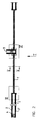
- Fig. 1 are in the illustrated embodiment two sliding doors symmetrical to each other provided in a wall 10. Between them runs how 2 and 4 can be seen, in particular normal outgoing wall 5.
- each of the sliding door leaves 1 in the cavity 2, which is between the plasterboard 3,3 'is formed, is displaceable.
- This plasterboard are in the floor area on a C-profile 24 attached in the usual way. It is especially out Fig. 2 shows that it is in the area between a stand 4 at the end of the path of movement of the door leaf 1 and Wall 5 is not possible to support and a stand Stiffening the wall in which the sliding door 1 is housed is to provide.
- this omitted stand 5 takes over the U-profile shown in FIG 6, the entire length between the stand 4 and the subsequent wall 5 is sufficient.
- This U profile also carries the actual running track on its web 7 for the sliding door leaf 1.
- this track 7 which is usually made of aluminum, on one even after erection the wall interchangeably attached to the U-profile 6: For this carries the U-profile on its closest to the stand 4 End of a tab protruding towards the door opening (or Tongue) 8, into which the web of the aluminum profile is inserted can be. In the area where the U profile 6 emerges from the wall is a fastening of the aluminum profile on the U-profile using one or more Screws 9 or the like. possible, and from then on over the total length of the free passage.
- the sliding track 7 for sliding doors is up to 20 kg one meter passage width is quite capable of that Wear door leaf without causing undue deformation is coming.
- each of the two sides of the wall is made of Gypsum plasterboard wall made up of two flat surfaces Plasterboard 12.13.
- each frame part 11 now has at least two vertical ones Spaces from each other (Fig. 1) each one Fastening tab 14 on when installing the frame pushed between the two plasterboard panels 12, 13 becomes.
- the length of this tab is in the horizontal direction larger than the frame level, so that it is possible to use the Tab with the usual fastening screws for plasterboard walls, indicated at 15 to attach. Whether two or several fastening screws can be used per tab or whether even just one is sufficient on a case by case basis Assess the circumstances.
- the vertical frame part opposite the frame parts 11 16 can usually be found in the normal repertoire the frame base can be removed for dry construction, there are surrounding frames or the like. on, but in shown embodiment shown a special case, because here the sliding door is flush with a right-angled one Wall 5 hits.
- a special, symmetrical training Frame 16 used with several screws through the double wall of the dry lining is screwed to a U-profile 17.
- a special, symmetrical training Frame 16 used with several screws through the double wall of the dry lining is screwed to a U-profile 17.
- leg to leg with the U-profile 17 provided a further U-profile 18 carries a cover strip 19 made of plasterboard, but this configuration can of course also be different respectively.
- the lintel 20 of the frame is like the vertical part 11 executed in two parts and according to the invention by horizontal Insert in the direction of arrow M in the 6 and 7 between the previously set up and assembled vertical frame parts 11, 16 mounted. This is to the the lintel 20 face areas of the frame parts 11, 16 a tab 22 is fastened and the frame lintels 20 wear angled sheet metal strips 23, which in the tabs grab and hold the lintel 20 with friction.
- the invention is not based on the illustrated embodiment limited, but can be modified in various ways become. So it is possible to change the shape of the vertical Frame parts 11, 16 to the desired and with the to match other shapes of the building to match it is possible to fix the running rail 7 on the U-profile 9 in a different way than that shown is to be carried out, especially on the side inwardly projecting ledges or tabs, which on U-profile 6 are provided and in the manner of wedges bracket strips can still be pushed.
- the system according to the invention makes it possible to use such Install doors and frames after setting up the walls, it is only necessary to take precautions that in Range of sliding movement of the door leaf 1 no vertical Stand are provided. If, in rare cases, only one single layer of plasterboard is provided, can the tabs 14 in this plasterboard are inserted, what their mechanical properties absolutely allow.
- the invention also allows the pockets to be as deep execute that the door leaf 1 entirely in it disappears and its face is flush with the opening-side frame level 21 completes.
- To close the door may have a preferably oblique end wall Bore should be provided, the one finger enough pad offers to the door leaf 1 at the start of the closing movement to pull out of your pocket.
Landscapes
- Engineering & Computer Science (AREA)
- Civil Engineering (AREA)
- Structural Engineering (AREA)
- Wing Frames And Configurations (AREA)
Applications Claiming Priority (3)
| Application Number | Priority Date | Filing Date | Title |
|---|---|---|---|
| AT154897 | 1997-09-15 | ||
| AT1548/97 | 1997-09-15 | ||
| AT0154897A ATA154897A (de) | 1997-09-15 | 1997-09-15 | Schiebetüre für den trockenen innenausbau |
Publications (2)
| Publication Number | Publication Date |
|---|---|
| EP0902149A2 true EP0902149A2 (fr) | 1999-03-17 |
| EP0902149A3 EP0902149A3 (fr) | 2000-07-05 |
Family
ID=3515783
Family Applications (1)
| Application Number | Title | Priority Date | Filing Date |
|---|---|---|---|
| EP98890264A Withdrawn EP0902149A3 (fr) | 1997-09-15 | 1998-09-14 | Porte coulissante pour murs en construction à sec |
Country Status (5)
| Country | Link |
|---|---|
| EP (1) | EP0902149A3 (fr) |
| AT (1) | ATA154897A (fr) |
| CZ (1) | CZ293998A3 (fr) |
| HU (1) | HU220056B (fr) |
| PL (1) | PL189254B1 (fr) |
Cited By (2)
| Publication number | Priority date | Publication date | Assignee | Title |
|---|---|---|---|---|
| EP1681428A1 (fr) * | 2005-01-13 | 2006-07-19 | KRONA I S.p.A. | Ensemble de structure pour une porte coulissante à encastrer dans une paroi |
| JP2017008525A (ja) * | 2015-06-18 | 2017-01-12 | 大和ハウス工業株式会社 | 戸袋構造 |
Citations (2)
| Publication number | Priority date | Publication date | Assignee | Title |
|---|---|---|---|---|
| US4325204A (en) | 1980-01-10 | 1982-04-20 | Martine Walter I | Door construction |
| WO1990013725A1 (fr) | 1989-05-05 | 1990-11-15 | Gyproc Ab | Amelioration apportee a un mur muni d'une porte coulissant |
Family Cites Families (1)
| Publication number | Priority date | Publication date | Assignee | Title |
|---|---|---|---|---|
| FR2745601B1 (fr) * | 1996-02-29 | 1998-11-13 | Richard Malie | Systeme de porte coulissante |
-
1997
- 1997-09-15 AT AT0154897A patent/ATA154897A/de not_active Application Discontinuation
-
1998
- 1998-09-14 PL PL98328558A patent/PL189254B1/pl not_active IP Right Cessation
- 1998-09-14 HU HU9802071A patent/HU220056B/hu not_active IP Right Cessation
- 1998-09-14 EP EP98890264A patent/EP0902149A3/fr not_active Withdrawn
- 1998-09-15 CZ CZ982939A patent/CZ293998A3/cs unknown
Patent Citations (2)
| Publication number | Priority date | Publication date | Assignee | Title |
|---|---|---|---|---|
| US4325204A (en) | 1980-01-10 | 1982-04-20 | Martine Walter I | Door construction |
| WO1990013725A1 (fr) | 1989-05-05 | 1990-11-15 | Gyproc Ab | Amelioration apportee a un mur muni d'une porte coulissant |
Cited By (2)
| Publication number | Priority date | Publication date | Assignee | Title |
|---|---|---|---|---|
| EP1681428A1 (fr) * | 2005-01-13 | 2006-07-19 | KRONA I S.p.A. | Ensemble de structure pour une porte coulissante à encastrer dans une paroi |
| JP2017008525A (ja) * | 2015-06-18 | 2017-01-12 | 大和ハウス工業株式会社 | 戸袋構造 |
Also Published As
| Publication number | Publication date |
|---|---|
| PL189254B1 (pl) | 2005-07-29 |
| HUP9802071A1 (hu) | 1999-06-28 |
| PL328558A1 (en) | 1999-03-29 |
| HU220056B (hu) | 2001-10-28 |
| CZ293998A3 (cs) | 1999-04-14 |
| EP0902149A3 (fr) | 2000-07-05 |
| ATA154897A (de) | 2000-01-15 |
| HU9802071D0 (en) | 1998-11-30 |
Similar Documents
| Publication | Publication Date | Title |
|---|---|---|
| DE3726255C2 (de) | Trennwand | |
| AT518814B1 (de) | Zaunsystem sowie Montageverfahren für ein Zaunsystem | |
| DE2339334C3 (de) | Zweischalige, versetzbare Trennwand | |
| DE1658834A1 (de) | Gebaeudetrenn- oder Zwischenwaende aus Fertigbauteilen | |
| DE2405055A1 (de) | Schall, temperatur und feuer daemmendes wandelement und verwendung desselben als schiebewand | |
| EP0918127B1 (fr) | Châssis de porte et dispositif de montage | |
| DE2546754A1 (de) | Einrichtung zur verbindung von elementen von trennwaenden | |
| EP0902149A2 (fr) | Porte coulissante pour murs en construction à sec | |
| DE9313426U1 (de) | Lüftungsvorrichtung für Räume | |
| EP0257547A2 (fr) | Carter de volet à rouleau | |
| DE3800446C2 (de) | Profilleiste für die Errichtung von Trennwänden u.dgl., insbesondere für Dusch- oder Badewannenabtrennungen | |
| AT408123B (de) | Zarge für eine schiebetüre für den trockenen innausbau | |
| DE2523314A1 (de) | Bausatz zum erstellen einer duschkabine | |
| DE3202833A1 (de) | Verkleidung fuer eine in einem bauwerk befestigte zarge fuer eine zimmer- oder haustuere oder dgl. | |
| DE2439167A1 (de) | Trennwand | |
| DE2117645A1 (de) | Türzarge mit beiderseitig vorgesehenem Mauerabschluß | |
| DE2343049A1 (de) | Mobile trennwand mit vertikalen verbindungsgliedern | |
| DE1952195U (de) | Zum unmittelbaren einsetzen in fenster- und tueroeffnungen eines rohbaues bestimmtes fenster- bzw. tuer-fertigbauteil. | |
| DE202004010160U1 (de) | Universalprofil | |
| DE1658915C3 (de) | Trennwand | |
| DE29708747U1 (de) | Fenster-, Türanordnung o.dgl. | |
| DE202022000276U1 (de) | Leicht montierbare einteilige Führungsvorrichtung zur zuverlässigen Führung von hängenden Schiebetüren und eine Schiebetürvorrichtung zur verkantungsfrei bedienbaren Führung einer Schiebetür | |
| DE3544297A1 (de) | Tuerfluegel | |
| EP0213451A2 (fr) | Rail pour une construction de support d'un bardage de mur ou plafond | |
| DE1509367C (de) | Turfutter , bei dem ein Bhndfutter, durch ein aus Fertigteilen bestehendes Über futter verkleidet ist |
Legal Events
| Date | Code | Title | Description |
|---|---|---|---|
| PUAI | Public reference made under article 153(3) epc to a published international application that has entered the european phase |
Free format text: ORIGINAL CODE: 0009012 |
|
| AK | Designated contracting states |
Kind code of ref document: A2 Designated state(s): AT DE ES IT |
|
| AX | Request for extension of the european patent |
Free format text: AL;LT;LV;MK;RO;SI |
|
| PUAL | Search report despatched |
Free format text: ORIGINAL CODE: 0009013 |
|
| AK | Designated contracting states |
Kind code of ref document: A3 Designated state(s): AT BE CH CY DE DK ES FI FR GB GR IE IT LI LU MC NL PT SE |
|
| AX | Request for extension of the european patent |
Free format text: AL;LT;LV;MK;RO;SI |
|
| 17P | Request for examination filed |
Effective date: 20010105 |
|
| AKX | Designation fees paid |
Free format text: AT DE ES IT |
|
| STAA | Information on the status of an ep patent application or granted ep patent |
Free format text: STATUS: THE APPLICATION IS DEEMED TO BE WITHDRAWN |
|
| 18D | Application deemed to be withdrawn |
Effective date: 20040701 |