EP0902149A2 - Sliding door for use in dry construction - Google Patents
Sliding door for use in dry construction Download PDFInfo
- Publication number
- EP0902149A2 EP0902149A2 EP98890264A EP98890264A EP0902149A2 EP 0902149 A2 EP0902149 A2 EP 0902149A2 EP 98890264 A EP98890264 A EP 98890264A EP 98890264 A EP98890264 A EP 98890264A EP 0902149 A2 EP0902149 A2 EP 0902149A2
- Authority
- EP
- European Patent Office
- Prior art keywords
- profile
- door
- wall
- frame
- Prior art date
- Legal status (The legal status is an assumption and is not a legal conclusion. Google has not performed a legal analysis and makes no representation as to the accuracy of the status listed.)
- Withdrawn
Links
Images


Classifications
-
- E—FIXED CONSTRUCTIONS
- E06—DOORS, WINDOWS, SHUTTERS, OR ROLLER BLINDS IN GENERAL; LADDERS
- E06B—FIXED OR MOVABLE CLOSURES FOR OPENINGS IN BUILDINGS, VEHICLES, FENCES OR LIKE ENCLOSURES IN GENERAL, e.g. DOORS, WINDOWS, BLINDS, GATES
- E06B3/00—Window sashes, door leaves, or like elements for closing wall or like openings; Layout of fixed or moving closures, e.g. windows in wall or like openings; Features of rigidly-mounted outer frames relating to the mounting of wing frames
- E06B3/32—Arrangements of wings characterised by the manner of movement; Arrangements of movable wings in openings; Features of wings or frames relating solely to the manner of movement of the wing
- E06B3/34—Arrangements of wings characterised by the manner of movement; Arrangements of movable wings in openings; Features of wings or frames relating solely to the manner of movement of the wing with only one kind of movement
- E06B3/42—Sliding wings; Details of frames with respect to guiding
- E06B3/46—Horizontally-sliding wings
- E06B3/4654—Horizontally-sliding wings disappearing in pockets in the wall; Pockets therefor
Definitions
- the invention relates to a sliding door for the dry Interior fittings and an associated frame, with a U-profile or a rectangular profile horizontally above the door opening and mounted over the entire sliding path of the door leaf is on the web the actual track for the Door leaf is attached.
- Such a sliding door is from WO90 / 13725 A. known.
- the horizontal U-profile makes it dry erected wall at least essentially the necessary mechanical strength if this is given in WO-A is also not mentioned.
- plasterboard walls are usually used erected by vertically arranged on both sides and anchored in the floor and ceiling, mostly C- or U-shaped profiles (stands) one or usually two Gypsum plasterboards are screwed on.
- C- or U-shaped profiles stands
- the invention aims to avoid these disadvantages and to create a sliding door with a frame that is suitable for the Dry interior is suitable and the sheet the sliding door between the plasterboard walls the dry built wall runs.
- frames and sliding doors only after erection the plasterboard wall, as this Risk of damage to the sliding door and frame is significantly reduced, which is because of the increasingly common finished surfaces is becoming increasingly important.
- the invention achieves these goals in that the running rail at the end of one in her pocket Tab or tongue attached to the horizontal U-profile is held.
- the frame according to the invention is characterized in that it consists of profile parts, and that the pocket-side vertical frame parts by means of tabs, which between or pushed into the plasterboard and with it or screwed to them, attached to the finished wall become.
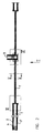
- Fig. 1 are in the illustrated embodiment two sliding doors symmetrical to each other provided in a wall 10. Between them runs how 2 and 4 can be seen, in particular normal outgoing wall 5.
- each of the sliding door leaves 1 in the cavity 2, which is between the plasterboard 3,3 'is formed, is displaceable.
- This plasterboard are in the floor area on a C-profile 24 attached in the usual way. It is especially out Fig. 2 shows that it is in the area between a stand 4 at the end of the path of movement of the door leaf 1 and Wall 5 is not possible to support and a stand Stiffening the wall in which the sliding door 1 is housed is to provide.
- this omitted stand 5 takes over the U-profile shown in FIG 6, the entire length between the stand 4 and the subsequent wall 5 is sufficient.
- This U profile also carries the actual running track on its web 7 for the sliding door leaf 1.
- this track 7 which is usually made of aluminum, on one even after erection the wall interchangeably attached to the U-profile 6: For this carries the U-profile on its closest to the stand 4 End of a tab protruding towards the door opening (or Tongue) 8, into which the web of the aluminum profile is inserted can be. In the area where the U profile 6 emerges from the wall is a fastening of the aluminum profile on the U-profile using one or more Screws 9 or the like. possible, and from then on over the total length of the free passage.
- the sliding track 7 for sliding doors is up to 20 kg one meter passage width is quite capable of that Wear door leaf without causing undue deformation is coming.
- each of the two sides of the wall is made of Gypsum plasterboard wall made up of two flat surfaces Plasterboard 12.13.
- each frame part 11 now has at least two vertical ones Spaces from each other (Fig. 1) each one Fastening tab 14 on when installing the frame pushed between the two plasterboard panels 12, 13 becomes.
- the length of this tab is in the horizontal direction larger than the frame level, so that it is possible to use the Tab with the usual fastening screws for plasterboard walls, indicated at 15 to attach. Whether two or several fastening screws can be used per tab or whether even just one is sufficient on a case by case basis Assess the circumstances.
- the vertical frame part opposite the frame parts 11 16 can usually be found in the normal repertoire the frame base can be removed for dry construction, there are surrounding frames or the like. on, but in shown embodiment shown a special case, because here the sliding door is flush with a right-angled one Wall 5 hits.
- a special, symmetrical training Frame 16 used with several screws through the double wall of the dry lining is screwed to a U-profile 17.
- a special, symmetrical training Frame 16 used with several screws through the double wall of the dry lining is screwed to a U-profile 17.
- leg to leg with the U-profile 17 provided a further U-profile 18 carries a cover strip 19 made of plasterboard, but this configuration can of course also be different respectively.
- the lintel 20 of the frame is like the vertical part 11 executed in two parts and according to the invention by horizontal Insert in the direction of arrow M in the 6 and 7 between the previously set up and assembled vertical frame parts 11, 16 mounted. This is to the the lintel 20 face areas of the frame parts 11, 16 a tab 22 is fastened and the frame lintels 20 wear angled sheet metal strips 23, which in the tabs grab and hold the lintel 20 with friction.
- the invention is not based on the illustrated embodiment limited, but can be modified in various ways become. So it is possible to change the shape of the vertical Frame parts 11, 16 to the desired and with the to match other shapes of the building to match it is possible to fix the running rail 7 on the U-profile 9 in a different way than that shown is to be carried out, especially on the side inwardly projecting ledges or tabs, which on U-profile 6 are provided and in the manner of wedges bracket strips can still be pushed.
- the system according to the invention makes it possible to use such Install doors and frames after setting up the walls, it is only necessary to take precautions that in Range of sliding movement of the door leaf 1 no vertical Stand are provided. If, in rare cases, only one single layer of plasterboard is provided, can the tabs 14 in this plasterboard are inserted, what their mechanical properties absolutely allow.
- the invention also allows the pockets to be as deep execute that the door leaf 1 entirely in it disappears and its face is flush with the opening-side frame level 21 completes.
- To close the door may have a preferably oblique end wall Bore should be provided, the one finger enough pad offers to the door leaf 1 at the start of the closing movement to pull out of your pocket.
Abstract
Description
Die Erfindung betrifft eine Schiebetüre für den trockenen Innenausbau und eine zugehörige Zarge, wobei ein U-Profil oder ein Rechteck-Profil horizontal über der Türöffnung und über den gesamten Schiebeweg des Türblattes montiert ist, an dessen Steg die eigentliche Laufschiene für das Türblatt befestigt ist.The invention relates to a sliding door for the dry Interior fittings and an associated frame, with a U-profile or a rectangular profile horizontally above the door opening and mounted over the entire sliding path of the door leaf is on the web the actual track for the Door leaf is attached.
Eine derartige Schiebetüre ist aus der WO90/13725 A bekannt. Durch das horizontale U-Profil wird der trocken errichteten Wand zumindest im wesentlichen die notwendige mechanische Festigkeit verliehen, wenn dies in der WO-A auch nicht erwähnt wird.Such a sliding door is from WO90 / 13725 A. known. The horizontal U-profile makes it dry erected wall at least essentially the necessary mechanical strength if this is given in WO-A is also not mentioned.
Im trockenen Innenausbau werden üblicherweise Gipskartonwände errichtet, indem zu beiden Seiten vertikal angeordneter und im Boden und der Decke verankerter, zumeist C- oder U-förmiger Profile (Ständer) eine oder zumeist zwei Gipskartonplatten angeschraubt werden. Es gibt eine ganze Reihe von Türen und Zargen für derartige Wände, die zur Erreichung der notwendigen mechanischen Festigkeit jeweils an C-Ständern der oben genannten Art befestigt werden, die zu beiden Seiten der Türe im unmittelbaren Zargenbereich vorgesehen sind.In dry interior construction, plasterboard walls are usually used erected by vertically arranged on both sides and anchored in the floor and ceiling, mostly C- or U-shaped profiles (stands) one or usually two Gypsum plasterboards are screwed on. There is a whole Series of doors and frames for such walls, which are used for Achieve the necessary mechanical strength in each case to be attached to C-stands of the type mentioned above, which on both sides of the door in the immediate frame area are provided.
Es besteht nun ein Bedarf an Schiebetüren, die in derartigen Wänden angeordnet sind. Es war vor der genannten WO A nicht möglich, Schiebetüren im Inneren der großteils hohlen Wände laufen zu lassen, da dann im Bereich der Schiebetüren sowohl über deren lichte Durchgangsweite, als auch in der Richtung, in der das Türblatt in die Wand einzuschieben ist, in einem weiteren ebensogroßen Bereich, kein Ständer eingebaut werden kann, wodurch die Festigkeit der umgebenden Wand leidet und die Anbringung einer Zarge nicht möglich ist. There is now a need for sliding doors that operate in such Walls are arranged. It was before the named WO A not possible, sliding doors inside the mostly hollow Let walls run, because then in the area of the sliding doors both over their clear passage width, as well in the direction in which the door leaf slides into the wall is, in another equally large area, none Stand can be installed, increasing the strength of the surrounding wall suffers and the attachment of a frame not possible.
Es ist aber auch bei der vorbekannten Schiebetüre und einer ähnlichen Schiebetüre gemäß der US-4,325,204 A nicht möglich, die Mechanik und die Türe samt Zarge erst nach der Montage der Wand anzubringen, wodurch oft Beschädigungen im Zuge des weiteren Ausbaues erfolgen. Auch ist es bei diesen Schiebetüren nicht möglich, eventuell beschädigte Zargen oder Laufschienen auszutauschen, ohne größere Demontagen von Wandteilen vorzunehmen, was im rauhen Alltagsbetrieb sehr nachteilig ist.But it is also with the previously known sliding door and a similar sliding door according to US 4,325,204 A is not possible, the mechanics and the door and frame only after mounting the wall, often causing damage in the course of further expansion. It is too not possible with these sliding doors, possibly replace damaged frames or tracks without make larger disassemblies of wall parts, what in rough everyday operation is very disadvantageous.
Die Erfindung bezweckt, diese Nachteile zu vermeiden und eine Schiebetür samt Zarge zu schaffen, die für den trockenen Innenausbau geeignet ist und bei der das Blatt der Schiebetür zwischen den Gipskartonwänden der trocken aufgebauten Wand verläuft. Insbesondere soll es möglich sein, derartige Zargen und Schiebetüren erst nach der Errichtung der Gipskartonwand zu montieren, da dadurch die Gefahr von Beschädigungen der Schiebetüre und der Zarge wesentlich herabgesetzt wird, was wegen der immer häufigeren endbearbeiteten Oberflächen immer wichtiger wird.The invention aims to avoid these disadvantages and to create a sliding door with a frame that is suitable for the Dry interior is suitable and the sheet the sliding door between the plasterboard walls the dry built wall runs. In particular, it should be possible such frames and sliding doors only after erection the plasterboard wall, as this Risk of damage to the sliding door and frame is significantly reduced, which is because of the increasingly common finished surfaces is becoming increasingly important.
Die Erfindung erreicht diese Ziele dadurch, daß die Laufschiene an ihrem in der Tasche liegenden Ende von einer Lasche, bzw. Zunge, die am horizontalen U-Profil befestigt ist, gehalten wird.The invention achieves these goals in that the running rail at the end of one in her pocket Tab or tongue attached to the horizontal U-profile is held.
Dadurch ist es möglich, die Laufschiene erst nach Fertigstellung der Wand durch Einschieben einer Zunge der Laufschiene in die Lasche bzw. durch Einschieben des Laufschienensteges unter die Zunge zu montieren.This makes it possible to run the track only after completion the wall by inserting a tongue of the running rail into the tab or by inserting the slide rail to mount under the tongue.
Die erfindungsgemäße Zarge ist dadurch gekennzeichnet, daß sie aus Profileinzelteilen besteht, und daß die taschenseitigen vertikalen Zargenteile mittels Laschen, die zwischen bzw. in die Gipskartonplatten geschoben und mit ihr bzw. ihnen verschraubt werden, an der fertigen Wand befestigt werden. The frame according to the invention is characterized in that it consists of profile parts, and that the pocket-side vertical frame parts by means of tabs, which between or pushed into the plasterboard and with it or screwed to them, attached to the finished wall become.
So erreicht man die notwendige mechanische Stabilität auch bei der Montage der Zarge an der fertigen Wand.This is how you achieve the necessary mechanical stability when installing the frame on the finished wall.
Die Erfindung wird anhand der folgenden Beschreibung unter
Bezugnahme auf die Zeichnung näher erläutert. Dabei zeigt
Wie aus Fig. 1 ersichtlich ist, sind im dargestellten Ausführungsbeispiel
zwei Schiebetüren symmetrisch zueinander
in einer Wand 10 vorgesehen. Zwischen ihnen verläuft, wie
insbesondere aus den Fig. 2 und 4 ersichtlich ist, eine
normal abgehende Wand 5.As can be seen from Fig. 1, are in the illustrated embodiment
two sliding doors symmetrical to each other
provided in a
Aus Fig. 2 ist ersichtlich, daß jedes der Schiebetürblätter
1 in den Hohlraum 2, der zwischen den Gipskartonplatten
3,3' ausgebildet ist, verschieblich ist. Diese Gipskartonplatten
sind im Bodenbereich an einem C-Profil 24
auf übliche Weise befestigt. Es ist insbesondere auch aus
Fig. 2 ersichtlich, daß es im Bereich zwischen einem Ständer
4 am Ende des Bewegungsweges des Türblattes 1 und der
Wand 5 nicht möglich ist, einen Ständer zur Stützung und
Versteifung der Wand, in der die Schiebetür 1 untergebracht
ist, vorzusehen.From Fig. 2 it can be seen that each of the sliding
Die mechanischen Aufgaben dieses wegfallenden Ständers
übernimmt erfindungsgemäß das aus Fig. 5 ersichtliche U-Profil
6, das über die gesamte Länge zwischen dem Ständer
4 und der anschließenden Wand 5 reicht. Die Gipskartonplatten
3,3' werden mit den üblichen selbstschneiden
Schrauben an diesem U-Profil befestigt. Dieses U-Profil
trägt darüberhinaus an seinem Steg die eigentliche Laufschiene
7 für das Schiebetürblatt 1.The mechanical tasks of this omitted
Erfindungsgemäß ist diese Laufschiene 7, die üblicherweise
aus Aluminium besteht, auf eine auch nach dem Errichten
der Wand austauschbare Weise am U-Profil 6 befestigt: Dazu
trägt das U-Profil an seinem dem Ständer 4 nächst gelegenen
Ende eine zur Türöffnung hinragende Lasche (bzw.
Zunge) 8, in die der Steg des Aluminiumprofils eingeschoben
werden kann. In dem Bereich, in dem das U-Profil
6 aus der Wand austritt, ist eine Befefestigung des Aluminiumprofils
am U-Profil mittels einer oder mehrerer
Schrauben 9 od.dgl. möglich, und von da an über die
gesamte Länge des freien Durchganges.According to the invention, this
Es ist selbverständlich möglich, mehrere derartige Laschen
bzw. Zungen in der Tasche vorzusehen, um eine mehrfache
Befestigung der Laufschiene zu erreichen. Es ist dann notwendig,
den Steg der laufschiene 7 mit entsprechenden Ausnehmungen
od.dgl. zu versehen, um ein gleichzeitiges Einschieben
in alle Befestigungsstellen zu ermöglichen.It is of course possible to have several such tabs
or tongues in the pocket to provide a multiple
To achieve fastening of the running rail. It is then necessary
the web of the running
Zum Austausch der Laufschiene 7 ist es nur nötig, die
jederzeit zugänglichen Schrauben 9 zu lösen und sodann die
Laufschiene durch leichtes Bewegen in Richtung zur
anschießenden Wand 5 aus dem Haltebreich der Lasche 8 zu
ziehen und eine neue Laufschiene 7 auf gleiche Weise einzuschieben
und am Profil 9 anzuschrauben.To replace the
Bei den üblicherweise auftretenden Türmassen von etwa
20 kg ist die Laufschiene 7 bei Schiebetüren mit bis zu
einem Meter Durchgangsbreite durchaus in der Lage, das
Türblatt zu tragen, ohne daß es zu unzulässigen Deformationen
kommt.With the usually occurring door masses of about
The sliding
In Fig. 3 ist ein erfindungsgemäß verwendbares Profil für
den vertikalen, schiebeseitigen Zargenteil 11 dargestellt.
Es werden, um Platz für den Durchtritt des Türblattes 1 zu
lassen, zwei getrennte Zargenteile 11 auf die stirnseitig
freistehenden Gipskartonplatten 3,3' aufgeschoben und montiert.
Wie üblich, besteht jede der beiden Wandseiten der
Gipskartonwand aus zwei flächig zueinander angeordneten
Gipskartonplatten 12,13.3 is a profile which can be used according to the invention for
the vertical, sliding-
Jeder Zargenteil 11 weist nun an zumindest zwei vertikalen
Abstand voneinander aufweisenden Stellen (Fig. 1) je eine
Befestigungslasche 14 auf, die bei der Montage der Zarge
zwischen die beiden Gipskartonplatten 12,13 geschoben
wird. Die Länge dieser Lasche in horizontaler Richtung ist
größer als der Zargenspiegel, so daß es möglich ist, die
Lasche mit den üblichen Befestigungsschrauben für Gipskartonwände,
angedeutet mit 15, zu befestigen. Ob zwei oder
mehrere Befestigungsschrauben pro Lasche verwendet werden
oder ob sogar nur eine reicht, ist von Fall zu Fall unter
Beurteilung der Gegebenheiten festzustellen.Each
Der den Zargenteilen 11 gegenüberliegende vertikale Zargenteil
16 kann üblicherweise aus dem normalen Repertoire
des Zargenfundus für den Trockenausbau entnommen werden,
es bieten sich Umfassungszargen od.dgl. an, doch wird im
gezeigten Ausführungsbeispiel ein Sonderfall dargestellt,
da hier die Schiebetüre stumpf an eine rechtwinkelig abgehende
Mauer 5 stößt.The vertical frame part opposite the
In diesem Fall wird eine besondere, symmetrisch ausgebildete
Zarge 16 verwendet, die mit mit mehreren Schrauben
durch die wiederum doppelt ausgeführte Wand des Trockenausbaues
an einem U-Profil 17 angeschraubt ist. Im dargestellten
Ausführungsbeispiel ist Schenkel an Schenkel mit
dem U-Profil 17 ein weiteres U-Profil 18 vorgesehen, das
einen Abdeckstreifen 19 aus Gipskartonplatten trägt, doch
kann selbstverständlich diese Ausgestaltung auch anders
erfolgen.In this case, a special,
Wie aus einem Zusammenhalt der Fig. 4 und 5 ersichtlich
ist, ist es durchaus möglich und selbverständlich mechanisch
empfehlenswert, das U-Profil 6 vom Ständer 4 bis zum
U-Profil 17 zu führen und an ihnen beispielsweise mittels
Winkeln zu befestigen, wodurch die Steifigkeit und der
mechanische Widerstand der Konstruktion wesentlich erhöht
wird. Wenn dies aus Gründen der Bauabfolge nicht möglich
ist, ist es in vielen Fällen immer noch möglich, die Zarge
16 oder die an ihrer Stelle verwendete übliche Zarge in
ihrem der Wand zugekehrten Stegbereich nach oben verlängert
in das darüberliegende Wandstück ragen zu lassen und
das U-Profil 6 daran zu befestigen.As can be seen from a cohesion of FIGS. 4 and 5
is, it is entirely possible and of course mechanical
recommendable, the
Im Falle einer geraden Fortführung des Mauerwerkes ist
selbstverständlich eine entsprechende Befestigung des U-Profiles
6 an dem dann dort üblicherweise befindlichen C-Ständer
möglich und mechanisch vorteilhaft.In the case of a straight continuation of the masonry
of course, a corresponding attachment of the
Der Sturz 20 der Zarge ist so wie der vertikale Teil 11
zweiteilig ausgeführt und wird erfindungsgemäß durch horizontales
Einschieben in Richtung des Pfeiles M in den
Fig. 6 und 7 zwischen die zuvor aufgestellten und montierten
vertikalen Zargenteile 11,16 montiert. Dazu ist an den
dem Sturz 20 zugekehrten Flächenbereichen der Zargenteile
11,16 eine Lasche 22 befestigt und die Zargenstürze 20
tragen abgewinkelte Blechstreifen 23, die in die Laschen
greifen und den Sturz 20 mit Reibschluß halten.The
Die Erfindung ist nicht auf das dargestellte Ausführungsbeispiel
beschränkt, sondern kann verschiedentlich abgewandelt
werden. So ist es möglich, die Form der vertikalen
Zargenteile 11,16 an die jeweils gewünschten und mit den
anderen Türen des Bauwerkes übereinstimmenden Formen anzupassen,
es ist möglich, die Befestigung der Laufschiene 7
am U-Profil 9 auf eine andere Weise als es die dargestellte
ist vorzunehmen, dazu eignen sich besonders seitlich
nach innen vorspringende Leisten oder Laschen, die am
U-Profil 6 vorgesehen sind und in die nach Art von Keilen
noch Halterungsleisten geschoben werden können. The invention is not based on the illustrated embodiment
limited, but can be modified in various ways
become. So it is possible to change the shape of the
Durch das erfindungsgemäße System ist es möglich, derartige
Türen samt Zargen nach dem Aufstellen der Wände einzubauen,
es muß nur Vorsorge getragen werden, daß im
Bereich der Schiebebewegung des Türblattes 1 keine vertikalen
Ständer vorgesehen werden. Wenn, in seltenen Fällen,
nur eine einlagige Gipskartonbelegung vorgesehen ist,
können die Laschen 14 in diese Gipskartonplatte
eingeschoben werden, was deren mechanische Eigenschaften
durchaus zulassen.The system according to the invention makes it possible to use such
Install doors and frames after setting up the walls,
it is only necessary to take precautions that in
Range of sliding movement of the
Die Erfindung erlaubt es auch, die Taschen so tief
auszuführen, daß das Türblatt 1 zur Gänze darin
verschwindet und seine Stirnfläche bündig mit der
öffnungsseitigen Zargenebene 21 abschließt. Zum Schließen
der Türe kann in deren Stirnwand eine bevorzugt schräge
Bohrung vorgesehen sein, die einem Finger genügend Auflage
bietet, um das Türblatt 1 zu Beginn der Schließbewegung
aus der Tasche zu ziehen.The invention also allows the pockets to be as deep
execute that the
Claims (4)
Applications Claiming Priority (3)
| Application Number | Priority Date | Filing Date | Title |
|---|---|---|---|
| AT0154897A ATA154897A (en) | 1997-09-15 | 1997-09-15 | SLIDING DOORS FOR DRY INTERIORS |
| AT1548/97 | 1997-09-15 | ||
| AT154897 | 1997-09-15 |
Publications (2)
| Publication Number | Publication Date |
|---|---|
| EP0902149A2 true EP0902149A2 (en) | 1999-03-17 |
| EP0902149A3 EP0902149A3 (en) | 2000-07-05 |
Family
ID=3515783
Family Applications (1)
| Application Number | Title | Priority Date | Filing Date |
|---|---|---|---|
| EP98890264A Withdrawn EP0902149A3 (en) | 1997-09-15 | 1998-09-14 | Sliding door for use in dry construction |
Country Status (5)
| Country | Link |
|---|---|
| EP (1) | EP0902149A3 (en) |
| AT (1) | ATA154897A (en) |
| CZ (1) | CZ293998A3 (en) |
| HU (1) | HU220056B (en) |
| PL (1) | PL189254B1 (en) |
Cited By (2)
| Publication number | Priority date | Publication date | Assignee | Title |
|---|---|---|---|---|
| EP1681428A1 (en) * | 2005-01-13 | 2006-07-19 | KRONA I S.p.A. | A structural assembly for sliding doors which can be recessed into the wall of a building |
| JP2017008525A (en) * | 2015-06-18 | 2017-01-12 | 大和ハウス工業株式会社 | Door pocket structure |
Citations (2)
| Publication number | Priority date | Publication date | Assignee | Title |
|---|---|---|---|---|
| US4325204A (en) | 1980-01-10 | 1982-04-20 | Martine Walter I | Door construction |
| WO1990013725A1 (en) | 1989-05-05 | 1990-11-15 | Gyproc Ab | Improvement in wall with a sliding door |
Family Cites Families (1)
| Publication number | Priority date | Publication date | Assignee | Title |
|---|---|---|---|---|
| FR2745601B1 (en) * | 1996-02-29 | 1998-11-13 | Richard Malie | SLIDING DOOR SYSTEM |
-
1997
- 1997-09-15 AT AT0154897A patent/ATA154897A/en not_active Application Discontinuation
-
1998
- 1998-09-14 PL PL98328558A patent/PL189254B1/en not_active IP Right Cessation
- 1998-09-14 HU HU9802071A patent/HU220056B/en not_active IP Right Cessation
- 1998-09-14 EP EP98890264A patent/EP0902149A3/en not_active Withdrawn
- 1998-09-15 CZ CZ982939A patent/CZ293998A3/en unknown
Patent Citations (2)
| Publication number | Priority date | Publication date | Assignee | Title |
|---|---|---|---|---|
| US4325204A (en) | 1980-01-10 | 1982-04-20 | Martine Walter I | Door construction |
| WO1990013725A1 (en) | 1989-05-05 | 1990-11-15 | Gyproc Ab | Improvement in wall with a sliding door |
Cited By (2)
| Publication number | Priority date | Publication date | Assignee | Title |
|---|---|---|---|---|
| EP1681428A1 (en) * | 2005-01-13 | 2006-07-19 | KRONA I S.p.A. | A structural assembly for sliding doors which can be recessed into the wall of a building |
| JP2017008525A (en) * | 2015-06-18 | 2017-01-12 | 大和ハウス工業株式会社 | Door pocket structure |
Also Published As
| Publication number | Publication date |
|---|---|
| HU220056B (en) | 2001-10-28 |
| ATA154897A (en) | 2000-01-15 |
| EP0902149A3 (en) | 2000-07-05 |
| CZ293998A3 (en) | 1999-04-14 |
| HU9802071D0 (en) | 1998-11-30 |
| HUP9802071A1 (en) | 1999-06-28 |
| PL328558A1 (en) | 1999-03-29 |
| PL189254B1 (en) | 2005-07-29 |
Similar Documents
| Publication | Publication Date | Title |
|---|---|---|
| DE3726255C2 (en) | partition wall | |
| DE1658834A1 (en) | Building partitions or partition walls made of prefabricated components | |
| AT518814B1 (en) | Fence system and assembly process for a fence system | |
| DE2405055A1 (en) | SOUND, TEMPERATURE AND FIRE INSULATING WALL ELEMENT AND USE OF IT AS A SLIDING WALL | |
| DE2546754A1 (en) | DEVICE FOR CONNECTING ELEMENTS OF PARTITION WALLS | |
| EP0902149A2 (en) | Sliding door for use in dry construction | |
| EP0918127B1 (en) | Door case and mounting device | |
| DE2358674A1 (en) | Universally adaptable aluminium door-frame assembly case - insertable into door fitting frame and fixable at variable interval from soffit | |
| DE102005033417B4 (en) | Sliding element | |
| AT408123B (en) | Frame for a sliding door for dry interior work | |
| EP0115554B1 (en) | Device for cladding a door frame | |
| DE2523314A1 (en) | Sliding door construction for shower cubicles - with grooved rollers on top of door sliding over guide rail | |
| DE3800446C2 (en) | Profile strip for the erection of partitions and the like, in particular for shower or bathtub partitions | |
| DE2343049C3 (en) | Movable partition made of floor-to-ceiling wall elements | |
| AT510431B1 (en) | blind frame | |
| DE202022000276U1 (en) | Easy-to-assemble one-piece guide device for reliable guidance of hanging sliding doors and a sliding door device for guiding a sliding door that can be operated without jamming | |
| CH371882A (en) | Wall for building | |
| DE1509367C (en) | Turf lining, in which a Bhndfutter is covered by an over lining made of prefabricated parts | |
| DE7234902U (en) | Door frame made of metal or plastic | |
| DE1161000B (en) | Attachment of a door lining or the like. | |
| DE2063156A1 (en) | Door frame | |
| EP1273751A1 (en) | Fixture for a rail of a room partition frame and a frame element provided with said fixture | |
| DE2045981A1 (en) | Door frame made of sheet metal, sheet steel or plastic, etc. | |
| EP1312740A1 (en) | Door system | |
| DE3711713A1 (en) | Window-sill structure consisting of solid wood |
Legal Events
| Date | Code | Title | Description |
|---|---|---|---|
| PUAI | Public reference made under article 153(3) epc to a published international application that has entered the european phase |
Free format text: ORIGINAL CODE: 0009012 |
|
| AK | Designated contracting states |
Kind code of ref document: A2 Designated state(s): AT DE ES IT |
|
| AX | Request for extension of the european patent |
Free format text: AL;LT;LV;MK;RO;SI |
|
| PUAL | Search report despatched |
Free format text: ORIGINAL CODE: 0009013 |
|
| AK | Designated contracting states |
Kind code of ref document: A3 Designated state(s): AT BE CH CY DE DK ES FI FR GB GR IE IT LI LU MC NL PT SE |
|
| AX | Request for extension of the european patent |
Free format text: AL;LT;LV;MK;RO;SI |
|
| 17P | Request for examination filed |
Effective date: 20010105 |
|
| AKX | Designation fees paid |
Free format text: AT DE ES IT |
|
| STAA | Information on the status of an ep patent application or granted ep patent |
Free format text: STATUS: THE APPLICATION IS DEEMED TO BE WITHDRAWN |
|
| 18D | Application deemed to be withdrawn |
Effective date: 20040701 |