JP2017008525A - Door pocket structure - Google Patents
Door pocket structure Download PDFInfo
- Publication number
- JP2017008525A JP2017008525A JP2015123126A JP2015123126A JP2017008525A JP 2017008525 A JP2017008525 A JP 2017008525A JP 2015123126 A JP2015123126 A JP 2015123126A JP 2015123126 A JP2015123126 A JP 2015123126A JP 2017008525 A JP2017008525 A JP 2017008525A
- Authority
- JP
- Japan
- Prior art keywords
- wall
- neutral
- door pocket
- plate
- pocket structure
- Prior art date
- Legal status (The legal status is an assumption and is not a legal conclusion. Google has not performed a legal analysis and makes no representation as to the accuracy of the status listed.)
- Granted
Links
Images


Abstract
Description
この発明は、上方部材と下方部材との間に設けられ、引込み戸を収納部に収納する戸袋構造に関する。 The present invention relates to a door pocket structure that is provided between an upper member and a lower member and stores a retractable door in a storage portion.
従来より、建物の内部において、出入り口を開閉するための建具として、引込み戸が多用されている。この引込み戸を開けたときに、引込み戸を収納させる構造として、戸袋が知られている。 Conventionally, a retractable door is frequently used as a fitting for opening and closing an entrance in a building. A door pocket is known as a structure for storing a retractable door when the retractable door is opened.
特開2008−75421号公報(特許文献1)、特開2006−225998号公報(特許文献2)、特開2006−70482号公報(特許文献3)には、引込み戸の戸袋が開示されている。このような戸袋において、戸袋を構成する中方立と石膏ボードとは、突き付け構造であることが開示されている。 JP-A-2008-75421 (Patent Document 1), JP-A-2006-225998 (Patent Document 2), and JP-A-2006-70482 (Patent Document 3) disclose a door pocket of a retractable door. . In such a door pocket, it is disclosed that the neutral and the gypsum board constituting the door pocket have a pressing structure.
中方立は、鴨居材の中央位置に配置されるため、強度を出す必要がある。しかしながら、戸袋部の壁厚が限られた中で、戸袋部の強度を出すことは困難であった。 Since the central stand is arranged at the center position of the Kamoi material, it is necessary to increase the strength. However, it was difficult to increase the strength of the door pocket while the wall thickness of the door pocket was limited.
本発明は、上記のような課題を解決するためになされたものであって、その目的は、施工精度の向上と強度を確保することが可能な戸袋構造を提供することである。 The present invention has been made to solve the above-described problems, and an object of the present invention is to provide a door pocket structure capable of ensuring improvement in construction accuracy and strength.
この目的のため、本発明の一態様に係る戸袋構造は、上方部材と下方部材との間に設けられ、引込み戸を収納部に収納する。戸袋構造は、上端部が上方部材に当接し、下端部が下方部材に当接して、上下方向に延び、収納部を介して対向して設けられる一対の中方立と、上方部材と下方部材との間に配置され、収納部の側壁部を形成する一対の板材とを備える。中方立のうち少なくとも一方は、収納部に面する内壁と、収納部から板材の厚み方向に離れて設けられる外壁と、内壁と外壁とをつなぐ端壁とを含み、内壁と外壁との間に、引込み戸の引き出し方向に見て板材の前方側の端部を受け入れる開口を有し、開口が板材の端部を受け入れた状態では、中方立の内壁、外壁および端壁は、板材の前方側端部の内面、外面および端面とそれぞれ対面する。 For this purpose, the door pocket structure according to one aspect of the present invention is provided between the upper member and the lower member, and stores the retractable door in the storage portion. The door pocket structure has a pair of neutral stands that have an upper end abutting on the upper member, a lower end abutting on the lower member, extending in the vertical direction and facing each other via the storage portion, and an upper member and a lower member. And a pair of plate members that form a side wall portion of the storage portion. At least one of the neutral stands includes an inner wall facing the storage portion, an outer wall provided away from the storage portion in the thickness direction of the plate material, and an end wall connecting the inner wall and the outer wall, and between the inner wall and the outer wall. , Having an opening for receiving the front end of the plate as viewed in the pulling-out direction of the retracting door, and in a state where the opening has received the end of the plate, the neutral inner wall, the outer wall and the end wall are on the front side of the plate It faces each of the inner surface, outer surface and end surface of the end portion.
好ましくは、中方立の外壁は、外壁から内壁に向かって延びる折り曲げ壁を含み、開口の幅は、内壁と折り曲げ壁との間の間隔によって決定される。 Preferably, the neutral outer wall includes a bent wall extending from the outer wall toward the inner wall, and the width of the opening is determined by the distance between the inner wall and the bent wall.
好ましくは、開口の幅と、板材の厚みとは、略同一である。 Preferably, the width of the opening and the thickness of the plate material are substantially the same.
好ましくは、中方立は、金属性材料で形成される。 Preferably, the neutral is formed of a metallic material.
好ましくは、一対の中方立のうち他方は、一対の板材のうちの他方を受け入れるものであり、断面視矩形形状の第1部材と、第1部材に固定され、他方の板材を受け入れる断面視コの字形状の第2部材とを備える。 Preferably, the other of the pair of neutrals is one that receives the other of the pair of plate members, and is a first member having a rectangular shape in section and a cross-sectional view that is fixed to the first member and receives the other plate member. And a second member having a U-shape.
好ましくは、第1部材は、木製材料で形成され、第2部材は、金属性材料で形成される。 Preferably, the first member is made of a wooden material, and the second member is made of a metallic material.
本発明によれば、施工精度の向上と強度を確保することが可能な戸袋構造を提供することができる。 ADVANTAGE OF THE INVENTION According to this invention, the door pocket structure which can ensure the improvement of construction accuracy and intensity | strength can be provided.
本発明の実施の形態について図面を参照しながら詳細に説明する。なお、図中同一または相当部分には同一符号を付してその説明は繰り返さない。 Embodiments of the present invention will be described in detail with reference to the drawings. In the drawings, the same or corresponding parts are denoted by the same reference numerals and description thereof will not be repeated.
<実施の形態1>
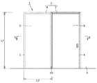
図1〜3を参照して、本実施の形態に係る戸袋構造1について説明する。図1において矢印L1で示す戸袋構造1の高さを上下方向とする。図1において矢印L2で示す戸袋構造1の横幅を左右方向という。特に、図2において矢印Aで示す方向を引込み戸9の引き出し方向とする。図2において矢印L3で示す戸袋構造1の厚さを奥行き方向とする。なお、図3において、引込み戸9と板材10の図示を省略している。
<
With reference to FIGS. 1-3, the
本実施の形態に係る戸袋構造1は、出入り口が開けられるときに引込み戸9が収納される構造であり、上方部材2と下方部材3との間に設けられる。上方部材2は、たとえば鴨居材であり、天井に直接的に設けられる部材であってもよいし、別部材を介して間接的に天井に設けられる部材であってもよい。また、下方部材3は、床材そのものであってもよいし、床材とは異なる部材、たとえば敷居材であってもよい。なお、引込み戸9のレールは、上方部材2に取り付けられていてもよいし、下方部材3に取り付けられていてもよいし、両方の部材2,3に取り付けられていてもよい。
The
本実施の形態に係る戸袋構造1は、上方部材2と下方部材3との間に設けられ、引込み戸9が収納される収納部6を有する。上方部材2および下方部材3の左右方向の両端側には、上方部材2を支持する1対の方立4,5が上下方向に設けられている。引込み戸9は、図2において、破線で示す左側位置と実線で示す右側位置との間をスライド移動し、引込み戸9が左側に移動すると出入り口が開けられ、引込み戸9が右側に移動すると出入り口が閉められた状態となる。
The
方立4は、引込み戸9の引き出し方向に見て先端側に位置し、方立5は、引込み戸9の引き出し方向に見て後端側に位置する。上方部材2は、出入り口側に形成される幅広部7と、収納部6側に形成される幅狭部8とを含んでいてもよい。幅広部7の奥行き方向の幅は、幅狭部8の幅よりも大きく形成される。上方部材2の左右方向の中央部、つまり幅広部7と幅狭部8との境界にあたる一対の角部には、後述する一対の中方立20が配置される。
The vertical 4 is positioned on the front end side when viewed in the pulling-out direction of the retracting door 9, and the vertical 5 is positioned on the rear end side when viewed in the pulling-out direction of the retracting door 9. The
戸袋構造1は、一対の中方立20と、一対の中方立20に受け入れられる一対の板材10とを備える。戸袋構造1の高さ寸法L1は、2700mm以下であり、望ましくは2400mm以下である。さらに、戸袋構造1の横幅L2は、たとえば、600〜1500mmである。戸袋構造1の厚さL3は、たとえば、60〜130mmである。
The
次に、板材10について説明する。板材10は、上方部材2と下方部材3との間に配置され、収納部6の側壁部を形成する。一対の板材10は、上方部材2と下方部材3との間に配置され、上下方向に延び、収納部6を介して対向して設けられる。板材10は、厚みを有する正面視矩形形状である。図5に示すように、板材10の厚みW1は、たとえば、10〜40mmである。
Next, the
板材10は、ある程度の強度を有する板状のものであればよく、たとえば、強化石膏ボードである。板材10として強化石膏ボードを用いることで、板材10の厚さW1を薄くすることができる。これにより、戸袋構造1全体の奥行き方向の厚みを薄くすることが可能であり、スペースが限られた住宅などで有効に利用することができる。なお、板材10の外面13、つまり外方側の全面には、たとえば壁紙が取り付けられていてもよい。
The board |
図4〜7をさらに参照して、中方立20について説明する。図4は、図2の一部分を拡大して示す断面図であり、図5は、板材10と中方立20と固定部材30との寸法関係を示す模式図であり、図6は、図4の矢印Vで示す方向から見た図であり、図7は、中方立20を取り出して示す斜視図である。一対の中方立20は、上端部が上方部材2に当接し、下端部が下方部材3に当接して、上下方向に延び、収納部6を介して対向して設けられる。中方立20は、たとえば金属性材料で形成され、具体的にはスチールで形成される。中方立20の厚みは、たとえば1〜3mmである。
The neutral 20 will be described with further reference to FIGS. 4 is a cross-sectional view showing a part of FIG. 2 in an enlarged manner, FIG. 5 is a schematic view showing a dimensional relationship among the
中方立20は、収納部6に面する内壁21と、収納部6から板材10の厚み方向に離れて設けられる外壁23と、内壁21と外壁23とをつなぐ端壁22とを含む。さらに、中方立20の外壁23は、外壁23から内壁21に向かって延びる折り曲げ壁24を含んでもよい。具体的には、中方立20の内壁21と端壁22とは垂直に連結され、端壁22と外壁23とは垂直に連結され、外壁23と折り曲げ壁24とは垂直に連結されていてもよい。また、内壁21の横幅は、外壁23の横幅よりも大きい。なお、端壁22および外壁23の角部と、外壁23および折り曲げ壁24の角部は、それぞれ面取りされていてもよい。また、端壁22の長さは、巾木の厚みにより決定されてもよい。
The
図4,5を特に参照して、中方立20は、内壁21と折り曲げ壁24との間に、開口25を有する。この開口25は、引込み戸9の引き出し方向に見て板材10の前方側の端部を受け入れる。この場合、中方立20の開口25の幅W2は、内壁21と折り曲げ壁24の間の間隔によって決定される。板材10の厚みW1と、開口25の幅W2とは、略同一である。なお、中方立20の外方側の全面には、樹脂塗装がされていてもよく、たとえば木目調のシールが貼られていてもよい。
With particular reference to FIGS. 4 and 5, the neutral 20 has an
上述したように、板材10の端部は、中方立20の開口25に受け入れられる。つまり、中方立20の開口25が板材10の端部を受け入れた状態では、中方立20の内壁21、折り曲げ壁24および端壁22は、板材10の前方側端部の内面11、外面13および端面12とそれぞれ対面する。具体的には、中方立20の内壁21と板材10の内面11とは当接し、中方立20の折り曲げ壁24と板材10の外面13とは当接する。このとき、中方立20の端壁22と板材10の端面12との間には隙間14が設けられていてもよい。
As described above, the end of the
このような構造とされることにより、板材10は、中方立20の内壁21と折り曲げ壁24で固定されているため、面外方向への変形を拘束することになる。これにより、面外方向からの力が加わっても、板材10の撓みを抑制することができ、戸袋構造1の剛性を保つことができる。したがって、簡易な方法であるにもかかわらず、戸袋構造1の品質を向上させることができる。
By adopting such a structure, the
図3に示すように、上方部材2の幅狭部8は、板材10の取り付け面との間に、薄板81を含んでいてもよい。薄板81の厚みは、内壁21の厚みと同一である。これにより、中方立20の上端を上方部材2に取り付けたときに、中方立20の内壁21が板材10に接する面と、薄板81が板材10に接する面とは、面一になる。
As shown in FIG. 3, the
図4〜6を参照して、固定部材30について説明する。固定部材30は、厚みが1〜2mm程度であり、鋼材などで形成されている。固定部材30は、一対の中方立20の間に配置されている。つまり、固定部材30は、一対の中方立20の内壁21に挟まれて配置されている。固定部材30は、断面視コの字形状であり、下方部材3に取り付けられるベース部31と、ベース部31から立ち上がる一対の立ち上がり部32とを含む。具体的には、一対の立ち上がり部32は、ベース部31の両端部から垂直に立ち上がる形状である。
The fixing
固定部材30のベース部31は、下方部材3に対して取り付けられている。さらに、立ち上がり部32は、中方立20の内壁21に固定され、内壁21と平行に設けられる。ベース部31の奥行き方向の長さW3と、一対の中方立20の内壁21間の間隔W4とは、同一である。これにより、上下方向における中方立20の間の間隔を一定に保つことができるため、中方立20を下方部材3に対して垂直に取り付けることができ、中方立20の固定精度が向上する。
The
図4〜6を参照して、レール部材40について説明する。レール部材40は、厚みが1〜2mm程度であり、鋼材などで形成されている。レール部材40は、引込み戸9の引き出し方向に見て固定部材30の後方側に配置されている。レール部材40は、断面視コの字形状であり、下方部材3に取り付けられるベース部41と、ベース部41から立ち上がる一対の立ち上がり部42とを含む。具体的には、一対の立ち上がり部42は、ベース部41の両端部から垂直に立ち上がる形状である。
The
レール部材40のベース部41は、下方部材3に対して取り付けられている。さらに、立ち上がり部42は、板材10の内面11に固定され、内面11と平行に設けられる。中方立20とレール部材40とを下方部材3に取り付けた状態では、中方立20の内壁21が板材10に当接する面と、レール部材40の立ち上がり部42が板材10に当接する面とは、面一である。
The
次に、図3を参照して、戸袋構造1の施工手順について説明する。
Next, with reference to FIG. 3, the construction procedure of the
まず、下方部材3に方立4,5を固定し、方立4,5の上端部に上方部材2を固定させる。さらに、上方部材2の左右方向中央部に、一方の中方立20を固定させる。このとき、中方立20の内壁21および端壁22で形成される角部と、上方部材2の幅狭部8および幅広部7で形成される角部とを当接させて、中方立20の内壁21と、上方部材2の幅狭部8とをネジ28で固定する。
First, the
次に、固定部材30を下方部材3に固定する。このとき、下方部材3と固定部材30のベース部31とをネジ33で固定する。中方立20の内壁21と、固定部材30の立ち上がり部32とをネジ26で固定する。
Next, the fixing
さらに、先に取り付けた中方立20と対向するように、他方の中方立20を配置させる。先に取り付けた中方立20と同様の要領で、他方の中方立20を上方部材2および固定部材30にネジ26,26で固定する。引込み戸9の引き出し方向に見て固定部材30の後端部側、すなわち、固定部材30と方立5との間に、レール部材40を配置して、レール部材40のベース部41と下方部材3とをネジ43で固定する。
Furthermore, the other neutral 20 is arranged so as to face the previously installed neutral 20. In the same manner as the previously attached
最後に、板材10を中方立20の開口25に挿入して固定する。このとき、板材10の取り付け面は、中方立20の内壁21、薄板81、レール部材40の立ち上がり部42および方立5であり、すべて面一である。つまり、これらの面は、同一平面上に位置する。これらの面に接着剤を塗布し、板材10を固定する。
Finally, the
このような構造とされることにより、中方立20の開口25に板材10の端部を差し込むという簡単な作業ですむため、施工時間を短縮することができる。さらに、板材10は複数の部材に固定されることになるが、それらはすべて面一であるため、高度な技術や、慎重な作業を行わずとも板材10の施工精度を上げることができる。
By adopting such a structure, the construction time can be shortened because a simple operation of inserting the end of the
なお、板材10を中方立20に取り付けた際には、中方立20の端壁22と板材10との間には、隙間14が形成されることが望ましい。この隙間14により、板材10の寸法の誤差を吸収することが可能である。さらに、板材10の角部を面取りしておくことが望ましい。これにより、開口25に板材10を挿入しやすくなる。なお、板材10を中方立20の開口25に挿入した後に、板材10と、上方部材2,立ち上がり部42,方立5とをネジ(図示せず)で固定してもよい。
When the
<実施の形態2>
上記実施の形態1では、収納部6を介して同じ形状の中方立20が一対設けられた。しかし、本実施の形態では、中方立の形状が異なる。
<
In the first embodiment, a pair of
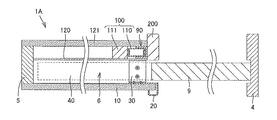
図9〜11を参照して、本実施の形態に係る戸袋構造1Aについて説明する。図9は、本実施の形態に係る戸袋構造1Aを示す断面図であり、図10は、本実施の形態における中方立200側の部分を示す分解斜視図であり、図11は、フレーム受入具を取り出して示す斜視図である。図10において、化粧材120,121の図示を省略している。
With reference to FIGS. 9-11, 1A of door pocket structures which concern on this Embodiment are demonstrated. 9 is a cross-sectional view showing the door pocket structure 1A according to the present embodiment, FIG. 10 is an exploded perspective view showing a portion on the
本実施の形態に係る戸袋構造1Aは、収納部6を介して、実施の形態1の中方立20と、断面視矩形形状の中方立200とを備える。以下の説明において、実施の形態1と同一の説明は、省略する。
The
中方立(第1部材)200は、断面矩形形状であり、たとえば木製材料で形成される。中方立200には、収納部6の側壁部を形成する戸袋パネル100と、戸袋パネル100を受け入れるフレーム受入具(第2部材)90とが取り付けられている。戸袋パネル100は、フレーム受入具90を介して、中方立200に間接的に取り付けられている。
The neutral stand (first member) 200 has a rectangular cross section, and is formed of, for example, a wooden material. To the
図10を参照して、収納部6の側壁部を形成する戸袋パネル100は、木製材料で形成される縦材111と、金属性材料で形成され、縦材111に重ね合わされる補強材110とを含んでいる。補強材110は、上下方向に延びる矩形形状であり、中空形状の鋼製スタッドである。補強材110のフレーム受入具90に対向する面と、縦材111に対向する面とには、断面矩形の溝が形成されている。なお、補強材110と縦材111とは、ネジ112が所定間隔で打ち込まれることにより、一体的に形成されていてもよい。また、引込み戸9を収納する収納部6側の全面には、化粧材120が取り付けられ、戸袋構造1の外側の全面には、化粧材121が取り付けられている。
Referring to FIG. 10, a
図11を参照して、フレーム受入具90は、たとえば金属性材料で形成され、具体的にはスチールで形成される。フレーム受入具90は、補強材110を受け入れる形状を有し、中方立200に固定される。フレーム受入具90は、断面略コの字形状であり、立壁91と、立壁91の両端から補強材110を受け入れる方向に突出する突出壁92,93とを含む。突出壁92,93の下端の間には、底壁94が設けられている。このような構造とされることで、フレーム受入具90の断面略コの字形状の部分に補強材110を挿入するだけでよいため、高度な技術や慎重な作業を行わずとも中方立200の固定精度を上げることができ、施工時間も短縮することができる。
Referring to FIG. 11,
このような構造とされることにより、中方立200側の奥行方向の幅を、中方立20側の奥行方向の幅よりも厚くすることができる。つまり、本実施の形態に係る戸袋構造を用いることで、戸袋構造の側壁の厚みを異ならせることが可能である。たとえば、手摺やトイレットペーパーホルダーなどは、厚みを有する壁に取り付けることが望ましい。したがって、本実施の形態に係る戸袋構造は、たとえば、廊下とトイレの境目に引込み戸を設ける場合に有効に利用することができる。この場合、トイレ側に中方立200、廊下側に中方立20が面するように配置させるとよい。
By adopting such a structure, the width in the depth direction on the neutral 200 side can be made larger than the width in the depth direction on the neutral 20 side. That is, it is possible to vary the thickness of the side wall of the door pocket structure by using the door pocket structure according to the present embodiment. For example, it is desirable that a handrail, a toilet paper holder or the like is attached to a wall having a thickness. Therefore, the door pocket structure according to the present embodiment can be effectively used when, for example, a retractable door is provided at the boundary between the hallway and the toilet. In this case, it is good to arrange so that the
なお、上記実施の形態1において、中方立20の外壁23は、外壁23から内壁21に向かって延びる折り曲げ壁24を含むとしたが、外壁23は折り曲げ壁24を含まなくてもよい。図8を参照して、板材10の端部を受け入れる開口25Aは、内壁21Aと外壁23Aとの間に設けられる。このとき、中方立20Aの内壁21A、外壁23Aおよび端壁22Aは、板材10の前方側端部の内面11、外面13および端面12とそれぞれ対面する。
In the first embodiment, the
また、上記実施の形態2において、戸袋パネル100は、縦材111と補強材110とから構成され、補強材110がフレーム受入具90に受け入れられるとしたが、限定的ではない。戸袋パネル100は、たとえば木製材料、金属材料、石膏ボードで形成されてもよい。
Moreover, in the said
また、本実施の形態2における中方立200は、溝を有さない断面矩形であるとしたが、これに限定されない。中方立200は、溝を有する断面コの字形状や、断面L字形状であってもよい。
Moreover, although the neutral 200 in this
また、上記各実施の形態において、固定部材30とレール部材40とは、下方部材3に取り付けられるとしたが、上方部材2に取り付けられていてもよい。
Further, in each of the above embodiments, the fixing
また、上記各実施の形態において、引込み戸が1枚である場合を説明したが、引込み戸は、複数枚設けられていてもよい。 Moreover, in each said embodiment, although the case where the number of the retractable doors was 1 was demonstrated, the multiple retractable doors may be provided.
以上、図面を参照してこの発明の実施の形態を説明したが、この発明は、図示した実施の形態のものに限定されない。図示した実施の形態に対して、この発明と同一の範囲内において、あるいは均等の範囲内において、種々の修正や変形を加えることが可能である。 Although the embodiments of the present invention have been described with reference to the drawings, the present invention is not limited to the illustrated embodiments. Various modifications and variations can be made to the illustrated embodiment within the same range or equivalent range as the present invention.
1 戸袋構造、2 上方部材、3 下方部材、4,5 方立、6 収納部、7 幅広部、8 幅狭部、9 引込み戸、10 板材、11 内面、12 端面、13 外面、14 隙間、20 中方立、21 内壁、22 端壁、23 外壁、24 折り曲げ壁、25 開口、26,28 ネジ、30 固定部材、31 ベース部、32 立ち上がり部、33 ネジ、40 レール部材、41 ベース部、42 立ち上がり部、43 ネジ、81 薄板、90 フレーム受入具(第2部材)、91 立壁、92,93 突出壁、94 底壁、100 戸袋パネル、110 補強材、111 縦材、112 ネジ、120,121 化粧材、200 中方立(第1部材)。
DESCRIPTION OF
Claims (6)
上端部が前記上方部材に当接し、下端部が前記下方部材に当接して、上下方向に延び、前記収納部を介して対向して設けられる一対の中方立と、
前記上方部材と前記下方部材との間に配置され、前記収納部の側壁部を形成する一対の板材とを備え、
前記中方立のうち少なくとも一方は、前記収納部に面する内壁と、前記収納部から前記板材の厚み方向に離れて設けられる外壁と、前記内壁と前記外壁とをつなぐ端壁とを含み、前記内壁と前記外壁との間に、前記引込み戸の引き出し方向に見て前記板材の前方側の端部を受け入れる開口を有し、
前記開口が前記板材の前記端部を受け入れた状態では、前記中方立の前記内壁、前記外壁および前記端壁は、前記板材の前方側端部の内面、外面および端面とそれぞれ対面する、戸袋構造。 It is provided between the upper member and the lower member, and is a door pocket structure for storing the retractable door in the storage portion,
A pair of neutral stands provided with an upper end abutting on the upper member, a lower end abutting on the lower member, extending in the vertical direction and facing each other via the storage unit;
A pair of plate members disposed between the upper member and the lower member and forming a side wall portion of the storage portion;
At least one of the neutral stands includes an inner wall facing the storage portion, an outer wall provided away from the storage portion in a thickness direction of the plate member, and an end wall connecting the inner wall and the outer wall, Between the inner wall and the outer wall, there is an opening for receiving the front end of the plate member as viewed in the pull-out direction of the retracting door,
In the state where the opening receives the end of the plate member, the neutral wall of the inner wall, the outer wall, and the end wall face the inner surface, the outer surface, and the end surface of the front end portion of the plate member, respectively. .
Priority Applications (1)
| Application Number | Priority Date | Filing Date | Title |
|---|---|---|---|
| JP2015123126A JP6670557B2 (en) | 2015-06-18 | 2015-06-18 | Door pocket structure |
Applications Claiming Priority (1)
| Application Number | Priority Date | Filing Date | Title |
|---|---|---|---|
| JP2015123126A JP6670557B2 (en) | 2015-06-18 | 2015-06-18 | Door pocket structure |
Publications (2)
| Publication Number | Publication Date |
|---|---|
| JP2017008525A true JP2017008525A (en) | 2017-01-12 |
| JP6670557B2 JP6670557B2 (en) | 2020-03-25 |
Family
ID=57761020
Family Applications (1)
| Application Number | Title | Priority Date | Filing Date |
|---|---|---|---|
| JP2015123126A Active JP6670557B2 (en) | 2015-06-18 | 2015-06-18 | Door pocket structure |
Country Status (1)
| Country | Link |
|---|---|
| JP (1) | JP6670557B2 (en) |
Citations (10)
| Publication number | Priority date | Publication date | Assignee | Title |
|---|---|---|---|---|
| US4325204A (en) * | 1980-01-10 | 1982-04-20 | Martine Walter I | Door construction |
| JPS60174786U (en) * | 1984-04-27 | 1985-11-19 | 日本橋住建株式会社 | hanging door unit |
| WO1990013725A1 (en) * | 1989-05-05 | 1990-11-15 | Gyproc Ab | Improvement in wall with a sliding door |
| EP0777030A1 (en) * | 1995-11-30 | 1997-06-04 | Polynorm N.V. | Sliding door and handling jamb therefor |
| EP0902149A2 (en) * | 1997-09-15 | 1999-03-17 | Novoferm Produktions- und Vertriebsgesellschaft m.b.H. | Sliding door for use in dry construction |
| JP2000291180A (en) * | 1999-04-12 | 2000-10-17 | Itoki Crebio Corp | Door pocket device for sliding door |
| JP2002309858A (en) * | 2002-03-05 | 2002-10-23 | Bunka Shutter Co Ltd | Sliding door apparatus and method for assembling the same |
| KR100657218B1 (en) * | 2005-12-12 | 2006-12-14 | 주식회사 아이테크 | A sliding-door receptacle |
| JP2007120179A (en) * | 2005-10-28 | 2007-05-17 | Nippon Spindle Mfg Co Ltd | Door frame member |
| JP2015036555A (en) * | 2013-08-12 | 2015-02-23 | カヤ工業株式会社 | Fluid draining pipe in piping and method and device for manufacturing the same |
-
2015
- 2015-06-18 JP JP2015123126A patent/JP6670557B2/en active Active
Patent Citations (10)
| Publication number | Priority date | Publication date | Assignee | Title |
|---|---|---|---|---|
| US4325204A (en) * | 1980-01-10 | 1982-04-20 | Martine Walter I | Door construction |
| JPS60174786U (en) * | 1984-04-27 | 1985-11-19 | 日本橋住建株式会社 | hanging door unit |
| WO1990013725A1 (en) * | 1989-05-05 | 1990-11-15 | Gyproc Ab | Improvement in wall with a sliding door |
| EP0777030A1 (en) * | 1995-11-30 | 1997-06-04 | Polynorm N.V. | Sliding door and handling jamb therefor |
| EP0902149A2 (en) * | 1997-09-15 | 1999-03-17 | Novoferm Produktions- und Vertriebsgesellschaft m.b.H. | Sliding door for use in dry construction |
| JP2000291180A (en) * | 1999-04-12 | 2000-10-17 | Itoki Crebio Corp | Door pocket device for sliding door |
| JP2002309858A (en) * | 2002-03-05 | 2002-10-23 | Bunka Shutter Co Ltd | Sliding door apparatus and method for assembling the same |
| JP2007120179A (en) * | 2005-10-28 | 2007-05-17 | Nippon Spindle Mfg Co Ltd | Door frame member |
| KR100657218B1 (en) * | 2005-12-12 | 2006-12-14 | 주식회사 아이테크 | A sliding-door receptacle |
| JP2015036555A (en) * | 2013-08-12 | 2015-02-23 | カヤ工業株式会社 | Fluid draining pipe in piping and method and device for manufacturing the same |
Also Published As
| Publication number | Publication date |
|---|---|
| JP6670557B2 (en) | 2020-03-25 |
Similar Documents
| Publication | Publication Date | Title |
|---|---|---|
| KR100256390B1 (en) | Wall board and the profiles of it | |
| JP6474637B2 (en) | Door pocket structure | |
| JP6421051B2 (en) | Joinery | |
| JP2017008525A (en) | Door pocket structure | |
| JP6128479B2 (en) | Lower end guide device | |
| JP6411861B2 (en) | Vertical support structure and vertical | |
| JP6669180B2 (en) | Storage box and method of manufacturing storage box | |
| GB2546508A (en) | Device for connecting components of a wall frame assembly and method of using said device | |
| JP6807731B2 (en) | Fixed structure of shelf board and construction method of shelf board | |
| JP2007146505A (en) | Panel of low partition or the like | |
| JP6503892B2 (en) | Mounting structure of sealing material in partition panel | |
| JP5357534B2 (en) | Tote panel | |
| JP2006263380A (en) | Method to install bathroom vanity to wall | |
| JP6166318B2 (en) | Window frame and window | |
| JP2014159681A (en) | Partition wall | |
| KR20150003307U (en) | Apparatus for connecting of wood block | |
| JP6081313B2 (en) | Joinery | |
| JP6299161B2 (en) | Panel plate locking device in earthquake-resistant partitioning device | |
| JP6080203B2 (en) | Partition panel | |
| JP4268544B2 (en) | Corrugated board support structure | |
| JP3145195U (en) | Building door frames and window frame materials | |
| JP6787809B2 (en) | Houses and fittings | |
| JP6567862B2 (en) | Mounting structure of building material having unevenness adjustment function and mounting structure of storage unit using the building material | |
| JP6649058B2 (en) | Furniture and its construction method | |
| JP2016132944A (en) | Wall panel |
Legal Events
| Date | Code | Title | Description |
|---|---|---|---|
| A621 | Written request for application examination |
Free format text: JAPANESE INTERMEDIATE CODE: A621 Effective date: 20180420 |
|
| A131 | Notification of reasons for refusal |
Free format text: JAPANESE INTERMEDIATE CODE: A131 Effective date: 20181120 |
|
| A521 | Request for written amendment filed |
Free format text: JAPANESE INTERMEDIATE CODE: A523 Effective date: 20190117 |
|
| A131 | Notification of reasons for refusal |
Free format text: JAPANESE INTERMEDIATE CODE: A131 Effective date: 20190312 |
|
| A521 | Request for written amendment filed |
Free format text: JAPANESE INTERMEDIATE CODE: A523 Effective date: 20190508 |
|
| A131 | Notification of reasons for refusal |
Free format text: JAPANESE INTERMEDIATE CODE: A131 Effective date: 20191008 |
|
| A521 | Request for written amendment filed |
Free format text: JAPANESE INTERMEDIATE CODE: A523 Effective date: 20191129 |
|
| TRDD | Decision of grant or rejection written | ||
| A01 | Written decision to grant a patent or to grant a registration (utility model) |
Free format text: JAPANESE INTERMEDIATE CODE: A01 Effective date: 20200218 |
|
| A61 | First payment of annual fees (during grant procedure) |
Free format text: JAPANESE INTERMEDIATE CODE: A61 Effective date: 20200302 |
|
| R150 | Certificate of patent or registration of utility model |
Ref document number: 6670557 Country of ref document: JP Free format text: JAPANESE INTERMEDIATE CODE: R150 |
|
| R250 | Receipt of annual fees |
Free format text: JAPANESE INTERMEDIATE CODE: R250 |