EP0901237B1 - Appareil de réception de type RAKE à AMRC - Google Patents
Appareil de réception de type RAKE à AMRC Download PDFInfo
- Publication number
- EP0901237B1 EP0901237B1 EP19980250309 EP98250309A EP0901237B1 EP 0901237 B1 EP0901237 B1 EP 0901237B1 EP 19980250309 EP19980250309 EP 19980250309 EP 98250309 A EP98250309 A EP 98250309A EP 0901237 B1 EP0901237 B1 EP 0901237B1
- Authority
- EP
- European Patent Office
- Prior art keywords
- reception
- section
- sections
- delay amount
- spreading
- Prior art date
- Legal status (The legal status is an assumption and is not a legal conclusion. Google has not performed a legal analysis and makes no representation as to the accuracy of the status listed.)
- Expired - Lifetime
Links
- 238000012545 processing Methods 0.000 claims description 135
- 238000001514 detection method Methods 0.000 claims description 87
- 238000005259 measurement Methods 0.000 claims description 22
- 238000010586 diagram Methods 0.000 description 16
- 238000012937 correction Methods 0.000 description 11
- 238000010276 construction Methods 0.000 description 9
- 230000005540 biological transmission Effects 0.000 description 4
- 238000006073 displacement reaction Methods 0.000 description 4
- 230000000694 effects Effects 0.000 description 4
- 238000000034 method Methods 0.000 description 4
- 238000012986 modification Methods 0.000 description 4
- 230000004048 modification Effects 0.000 description 4
- 230000008569 process Effects 0.000 description 4
- 230000001360 synchronised effect Effects 0.000 description 4
- 230000006866 deterioration Effects 0.000 description 3
- 238000005562 fading Methods 0.000 description 3
- 238000004891 communication Methods 0.000 description 2
- 230000007480 spreading Effects 0.000 description 2
- 238000010606 normalization Methods 0.000 description 1
- 238000001228 spectrum Methods 0.000 description 1
Images


Classifications
-
- H—ELECTRICITY
- H04—ELECTRIC COMMUNICATION TECHNIQUE
- H04B—TRANSMISSION
- H04B1/00—Details of transmission systems, not covered by a single one of groups H04B3/00 - H04B13/00; Details of transmission systems not characterised by the medium used for transmission
- H04B1/69—Spread spectrum techniques
- H04B1/707—Spread spectrum techniques using direct sequence modulation
- H04B1/7097—Interference-related aspects
- H04B1/711—Interference-related aspects the interference being multi-path interference
- H04B1/7113—Determination of path profile
-
- H—ELECTRICITY
- H04—ELECTRIC COMMUNICATION TECHNIQUE
- H04B—TRANSMISSION
- H04B7/00—Radio transmission systems, i.e. using radiation field
- H04B7/24—Radio transmission systems, i.e. using radiation field for communication between two or more posts
- H04B7/26—Radio transmission systems, i.e. using radiation field for communication between two or more posts at least one of which is mobile
-
- H—ELECTRICITY
- H04—ELECTRIC COMMUNICATION TECHNIQUE
- H04B—TRANSMISSION
- H04B1/00—Details of transmission systems, not covered by a single one of groups H04B3/00 - H04B13/00; Details of transmission systems not characterised by the medium used for transmission
- H04B1/69—Spread spectrum techniques
- H04B1/707—Spread spectrum techniques using direct sequence modulation
- H04B1/7097—Interference-related aspects
- H04B1/711—Interference-related aspects the interference being multi-path interference
- H04B1/7115—Constructive combining of multi-path signals, i.e. RAKE receivers
- H04B1/7117—Selection, re-selection, allocation or re-allocation of paths to fingers, e.g. timing offset control of allocated fingers
-
- H—ELECTRICITY
- H04—ELECTRIC COMMUNICATION TECHNIQUE
- H04B—TRANSMISSION
- H04B7/00—Radio transmission systems, i.e. using radiation field
- H04B7/14—Relay systems
- H04B7/15—Active relay systems
- H04B7/204—Multiple access
- H04B7/216—Code division or spread-spectrum multiple access [CDMA, SSMA]
-
- H—ELECTRICITY
- H04—ELECTRIC COMMUNICATION TECHNIQUE
- H04B—TRANSMISSION
- H04B1/00—Details of transmission systems, not covered by a single one of groups H04B3/00 - H04B13/00; Details of transmission systems not characterised by the medium used for transmission
- H04B1/69—Spread spectrum techniques
- H04B1/707—Spread spectrum techniques using direct sequence modulation
- H04B1/709—Correlator structure
-
- H—ELECTRICITY
- H04—ELECTRIC COMMUNICATION TECHNIQUE
- H04B—TRANSMISSION
- H04B1/00—Details of transmission systems, not covered by a single one of groups H04B3/00 - H04B13/00; Details of transmission systems not characterised by the medium used for transmission
- H04B1/69—Spread spectrum techniques
- H04B1/7163—Spread spectrum techniques using impulse radio
- H04B1/7183—Synchronisation
Definitions
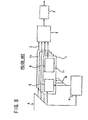
- a CDMA receiving apparatus for use with a mobile radio communication system for a portable telephone set or the like of the CDMA type conventionally has such a general construction as shown in FIG. 8.
- the CDMA receiving apparatus shown includes a plurality of FINGER processing sections 1 (FINGER processing sections 1 1 to 1 n ), a RAKE composition section 2, a decoding section 3 which performs decoding processing including error correction of a reception signal after detection, and a synchronization detection and phase tracking section 4.
- reference symbol A denotes a reception signal before de-spreading
- B a delay amount indication signal indicating the timing of de-spreading detected and instructed by the synchronization detection and phase tracking section 4
- C a reception signal after detection.
- the plural number of FINGER processing sections 1 1 to 1 n are provided corresponding to the paths.
- the term "FINGER" of the FINGER processing sections signifies a signal like a finger, and such processing sections are called FINGER processing sections since they process the reception signal A which is a finger-like signal.
- the RAKE composition section processes signals outputted from the FINGER processing sections like a rake.
- a reception signal A is a modulated signal whose signal spectrum was spread by a spread code when it is transmitted from the transmission side. Consequently, upon reception of the reception signal A, the synchronization detection and phase tracking section 4 modulates the reception signal A by successively displacing the phase of a de-spread code (same code as the spread code but inverse in polarity) to determine correlation magnitudes.
- a de-spread code as the spread code but inverse in polarity
- each phase of the de-spread code corresponding to the determined correlation magnitudes is indicated to the de-spreading sections 5 of the FINGER processing sections 1 1 to 1 n , that is, n phases of de-spread code (reception delay amounts) corresponding to comparatively high ones of the determined correlation magnitudes which are designated in the descending order.
- the correlators 8 of the de-spreading section 5 modulate the reception signal A with the de-spread code at the respective designated timings (phases) to de-spread the reception signal A, and outputs correlation magnitudes of the de-spread reception signal A to the channel estimator 12 and the detection section 13.
- Each reception signal A of the multi-paths can be separated by de-spreading the reception signal A at timings corresponding to the individual paths.
- the detection data C detected by the n FINGER processing sections 1 1 to 1 n in this manner are sent to and added by the RAKE composition section 2, and the result of the addition is outputted to the decoding section 3.
- the decoding section 3 performs decoding processing including error correction to the reception signal from the RAKE composition section 2.
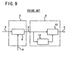
- FIG. 10 shows in block diagram a construction of a CDMA receiving apparatus disclosed in Japanese Patent Laid-Open Application No. Heisei 8-256084.
- a spread signal received by the antenna 101 is converted into a base band signal by the mixer 102 and the oscillator 103, and the base band signal is outputted to the correlator 104, de-spreading circuits 111 to 113 and the demodulation sections 118 to 120.
- the correlator 104 detects a correlation of the reception signal to a PN code (de-spread signal) same as that used on the transmission side while successively displacing the phase of the PN code to determine correlation magnitudes corresponding to a plurality of paths (in the arrangement shown in FIG. 10, the correlator 104 includes three correlators).
- the PN load signal control circuit 105 selects three phases which correspond to highest ones of the correlation magnitudes obtained by the correlator 104 in the descending order and outputs the three phases as PN load signals LDn (LD1 to LD3) to the PN generators 106 to 108.
- the PN generators 106 to 108 respectively generate PN signals PNn (PN1 to PN3) synchronized with the PN load signals LDn and clock signal from the delay lock loop circuits 115 to 117. Consequently, PN signals synchronized in phase with the multi-paths can be obtained.
- the PN signals PNn from the PN generators 106 to 108 are supplied to the demodulation sections 118 to 120, respectively, and the correlation magnitude detection circuit 110.
- the demodulation sections 118 to 120 demodulate the reception signal based on the PN signals PNn.
- the top bits of the PN signals PNn are supplied to the delay difference detection circuit 109.
- the delay difference detection circuit 109 detects phase differences of the PN codes PNn based on the received top bits of the PN signals PNn and controls the delay correction circuits 121 to 123 to correct the phase differences corresponding to the delay differences of the multi-paths.
- the correlation magnitude detection circuit 110 determines correlation magnitudes using the reception signal and the PN codes PNn supplied from the PN generators 106 to 108 to the demodulation sections 118 to 120.
- the multiplication circuits 124 to 126 multiply the demodulation signals from the demodulation sections 118 to 120 received through the delay correction circuits 121 to 123 by the correlation magnitudes of the correlation magnitude detection circuit 110 as weight coefficients and output results of the multiplication to the addition circuit 127, by which the results of the multiplication are added.
- the conventional CDMA receiving apparatus described above with reference to FIGS. 8 and 10 can accurately perform phase tracking for a spread reception signal whose reception delay amount (that is, timing of de-spreading) varies in a period substantially equal to the processing time of the synchronization detection and phase tracking section.
- the conventional CDMA receiving apparatus has a subject to be solved in that it cannot accurately perform phase tracking for another spread reception signal whose reception delay amount varies in a period shorter than the processing time of the synchronization detection and phase tracking section.
- the synchronization detection and phase tracking section searches for effective paths from within the reception signal and tracks the phase as a detected path, it performs processing to average obtained correlation magnitudes in a period of a frame of the signal. Accordingly, the conventional CDMA receiving apparatus cannot accurately perform phase tracking to the reception signal when the reception delay amount varies in a period shorter than the average processing time of the synchronization detection and phase tracking section.
- a CDMA receiving apparatus comprising a plurality of reception processing sections individually including de-spreading sections for receiving a signal spread with a spread code and arriving through a plurality of paths as a reception signal and de-spreading the inputted reception signal with a de-spread code and channel estimation sections for estimating the paths based on results of the processing of the de-spreading sections, and a synchronization detection and phase tracking section for outputting reception delay amounts of the reception signal in a predetermined period to the de-spreading sections of the reception processing sections, each of the de-spreading sections including a plurality of correlators for individually correcting, when the reception delay amounts are received from the synchronization detection and phase tracking section, the reception delay amounts and performing de-spreading processing, each of the channel estimation sections including a plurality of level measurement sections for individually receiving the correlation magnitudes outputted from the corresponding plurality of correlators to measure levels of the correlation magnitudes, a level
- the plurality of correlators include a first correlator for performing de-spreading with a phase of a delay amount indicated by the synchronization detection and phase tracking section and outputting a resulting correlation value, a second correlator for performing de-spreading with a phase leading, where 1 bit of a spread code is represented by 1 chip, by 0.5 chips from the delay amount indicated by the synchronization detection and phase tracking section and outputting a resulting correlation value, a third correlator for performing de-spreading with a phase lagging by 0.5 chips from the delay amount indicated by the synchronization detection and phase tracking section and outputting a resulting correlation value, a fourth correlator for performing de-spreading with a phase leading by 0.25 chips from the delay amount indicated by the synchronization detection and phase tracking section and outputting a resulting correlation value, and a fifth correlator for performing de-spreading with a phase lagging by 0.25 chips from the delay amount indicated by the synchronization detection and phase tracking
- the CDMA receiving apparatus further comprises a delay amount comparison section for comparing the reception delay amounts of the correlators selected by the path change-over sections of the plurality of reception processing sections and allowing, when a plurality of the reception processing sections exhibitsan equal reception delay amount, only one of the reception processing sections to perform reception processing.
- reception processing based on an equal reception delay amount by a plurality of the reception processing sections is eliminated. Consequently, the signal can be received accurately and otherwise possible deterioration of the reception signal quality can be prevented.
- the CDMA receiving apparatus may be constructed such that each of the reception processing sections includes a path selection section for selectively setting an effective path when an effective path signal is received from the delay amount comparison section so that whether a path is effective or ineffective can be indicated in accordance with the result of the comparison by the delay amount comparison section.
- the delay amount comparison section indicates, if the delay amounts being received by the reception processing sections at present are different from one another, with effective path signals to the path selection sections of the reception processing sections that their paths are effective so that the reception processing sections may perform reception processing with the signal delay amounts, but indicates, if the delay amount comparison section detects as a result of the comparison of the reception delay amounts from the reception processing sections that a plurality of ones of the reception processing sections receive with an equal delay amount, to the path selection section of only one of the reception processing sections with an effective path signal that its path is effective while the delay amount comparison section indicates to each of the path selection sections of the remaining ones of the reception processing sections with an effective path signal that its path is ineffective.
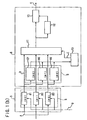
- FIG. 1(a) there is shown a CDMA receiving apparatus to which the present invention is applied.
- the CDMA receiving apparatus shown includes a plural number of FINGER processing sections 1 equal to the number of paths to be received, a RAKE composition section 2, a decoding section 3 and a synchronization detection and phase tracking section 4.
- n FINGER processing sections 1 (1 1 to 1 n ) are provided so that each signal from n paths can be received, respectively.
- the synchronization detection and phase tracking section 4 searches for and acquires an effective path from a reception signal A and tracks the reception signal A of the effective path. Consequently, the synchronization detection and phase tracking section 4 outputs reception delay amounts of the reception signal of the individual paths individually to the FINGER processing sections 1 1 to 1 n .
- each of the FINGER processing sections 1 (1 1 to 1 n ) described above includes a de-spreading section 5 which in turn includes three correlators 81 to 83.
- the FINGER processing section further includes a channel estimation section 6 which in turn includes three level measurement sections 9 (91 to 93), a level comparison section 10, a path change-over section 11, a channel estimator 12 and a detection section 13.
- the synchronization detection and phase tracking section 4 searches for effective paths from the reception signal A, allocates the FINGER processing sections 1 1 to 1 n for the individual paths and reports phases of de-spread codes corresponding to delay amounts of the individual paths to the correlators 82 of the FINGER processing sections 1 1 to 1 n .
- each of the correlators 81 performs processing with a phase leading by d of the de-spread code reported to the correlator 82 while each of the correlators 83 performs processing with a phase lagging by d of the de-spread code reported to the correlator 82.
- Each of the level measurement sections 91 to 93 calculates a correlation magnitude level from a received correlation magnitude and outputs the correlation magnitude level to the level comparison section 10.
- the level comparison section 10 compares the correlation magnitude levels from the correlators 81 to 83 and indicates that one of the correlators 81 to 83 which outputs the highest correlation magnitude level to the path change-over section 11.
- the path change-over section 11 selects one of the correlators 81 to 83 indicated by the level comparison section 10 and outputs the correlation magnitude of the selected one of the correlators 81 to 83 to the channel estimator 12 and the detection section 13.
- the channel estimator 12 performs estimation of a path using the output of the one of the correlators 81 to 83 selected by the path change-over section 11 to determine a channel estimation vector and outputs the channel estimation vector to the detection section 13.
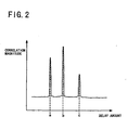
- the processing period of the synchronization detection and phase tracking sections 4 is substantially equal to the period of a frame of signal, there is the possibility that, due to an influence of fading within the processing period, the delay amounts indicated by the synchronization detection and phase tracking sections 4 and the delay amounts which actually exhibit a maximum correlation magnitude may become different from each other, resulting in variation of the correlation magnitude levels.
- An example of a delay profile in such an instance is shown in FIG. 3.
- the correlator 82 performs de-spreading with another phase leading by 0.25 chips from the delay amount indicated by the synchronization detection and phase tracking section 4 and outputs a resulting correlation magnitude.
- the correlator 83 performs de-spreading with a phase of the delay amount indicated by the synchronization detection and phase tracking section 4 and outputs a resulting correlation magnitude.
- each of the FINGER processing sections 1 1 to 1 n includes, in addition to the correlator 83 which outputs a correlation magnitude at a timing of a delay amount indicated by the synchronization detection and phase tracking section 4, the correlators 82 and 84 and the correlators 81 and 85 which output correlation magnitudes at intervals of ⁇ 0.25 chips and at intervals of ⁇ 0.5 chips, respectively.
- the level measurement sections 91 to 95 measure the correlation magnitude levels of the correlators 81 to 85, respectively, and output them to the level comparison section 10.
- the level comparison section 10 compares the correlation magnitude levels of the correlators 81 to 85 measured by the level measurement sections 91 to 95 and instructs the path change-over section 11 to select that one of the correlators 81 to 85 which outputs the highest correlation magnitude.
- the path change-over section 11 selects that one of the correlators 81 to 85 which exhibits the highest correlation magnitude level in accordance with the instruction from the level comparison section 10 and outputs the correlation magnitude of the selected one of the correlators 81 to 85.
- the channel estimator 12 effects estimation of the path using the output of that one of the correlators 81 to 85 selected by the path change-over section 11 to determine a channel estimation vector and outputs the channel estimation vector to the detection section 13.
- the detection section 13 multiplies the correlation magnitude outputted from the path change-over section 11 by the channel estimation vector outputted from the channel estimator 12 to interpolate symbol positions of the reception signal and outputs a result of the interpolation to the RAKE composition section 2.
- the RAKE composition section 2 performs weighted addition of the detection data outputted from the FINGER processing sections 1 1 to 1 n and outputs the result of the weighted addition to the decoding section 3.
- the decoding section 3 performs decoding processing including error correction processing for the weighted detected data.
- a reception signal A in the form of a spread signal is supplied to the synchronization detection and phase tracking section 4, which demodulates the reception signal A using a de-spread code, which is the same as a spread code used for spreading on the transmission side but inverse in polarity, while successively displacing the phase of the de-spread code little by little to determine correlation magnitudes.
- the synchronization detection and phase tracking section 4 determines one of correlation magnitude levels higher than a predetermined threshold value designated in advance and discriminates that the path corresponding to the correlation magnitude is an effective path.
- the de-spread code is set to the correlator 83 of the corresponding FINGER processing section 1 at a timing of the delay amount of the path discriminated to be effective.
- the de-spread code is set to the correlator 81 of the corresponding one of the FINGER processing sections 1 at a timing of a phase leading by 0.5 chips from the delay amount of the effective path, and the de-spread code is set to the correlator 82 of the FINGER processing section 1 at another timing of a phase leading by 0.25 chips from the delay amount of the effective path.
- the de-spread code is set to the correlator 84 of the corresponding FINGER processing section 1 at a timing of a phase lagging by 0.25 chips from the delay amount of the effective path, and the de-spread code is set to the correlator 85 of the corresponding FINGER processing section 1 at another timing of a phase delay by 0.5 chips from the delay amount of the effective path. Then, de-spreading processing is performed by the correlators 81 to 85 and resulting correlation magnitudes are outputted to the level measurement sections 91 to 95, respectively, and also to the path change-over section 11.
- the level measurement sections 91 to 95 measure the correlation magnitude levels of the correlators 81 to 85 and output them to the level comparison section 10.
- the level comparison section 10 instructs the path change-over section 11 to select one of the correlators 81 to 85 which outputs the height correlation magnitude.
- the path change-over section 11 selects one of the correlators 81 to 85 in accordance with the instruction.
- the channel estimator 12 and the detection section 13 perform channel estimation and detection processing, respectively, based on the selected output of the path change-over section 11.
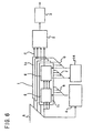
- FIG. 6 shows a block diagram of another CDMA receiving apparatus to which the present invention is applied.
- the CDMA receiving apparatus shown in FIG. 6 is a modification to but is different from the CDMA receiving apparatus described hereinabove with reference to FIG. 1(a) in that it additionally includes a delay amount comparison section 14 for receiving a reception delay amount F and outputting an effective path signal G.
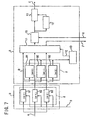
- FIG. 7 shows a block diagram of a FINGER processing section 1 of the CDMA receiving apparatus shown in FIG. 6.
- the FINGER processing section 1 shown in FIG. 7 is a modification to but is different from the FINGER processing section 1 described hereinabove with reference to FIG. 1(b) in that it additionally includes a path selection section 15. Further, the path change-over section 11 outputs a reception delay amount F mentioned above to the delay amount comparison section 14. The path selection section 15 selectively sets an effective path when it receives an effective path signal G from the delay amount comparison section 14.
- the delay amount of that one of the correlators 81 to 83 selected by the path change-over section 11 is outputted as a reception delay amount F to the delay amount comparison section 14.
- the delay amount comparison section 14 thus compares such reception delay amounts F outputted from the FINGER processing sections 1 1 to 1 n .
- the delay amount comparison section 14 indicates with effective path signals G to the path selection sections 15 of the FINGER processing sections 1 1 to 1 n that their paths are effective so that the FINGER processing sections 1 1 to 1 n may perform reception processing with the signal delay amounts.
- the CDMA receiving apparatus has such a construction described above with reference to FIGS. 6 and 7, one of the two FINGER processing sections 1 1 and 1 2 which receive with the delay amount b - d and the delay amount a - d, respectively, is disabled so that it cannot receive a signal. Consequently, the CDMA receiving apparatus can receive the signal accurately, and accurate reception and reception signal quality measurement can be maintained.
- the signal can be received accurately, and consequently, otherwise possible deterioration of the reception signal quality can be prevented.
- each FINGER processing section includes a plurality of correlators having de-spread timings and one of the correlators which exhibits the highest correlation magnitude is selectively used for reception, even if the reception delay amount varies in a period shorter than the processing time of the synchronization detection and phase tracking sections 4, phase tracking can be performed.
- the problem of the conventional CDMA receiving apparatus that, if a displacement is produced between an instruction of a reception delay amount from a synchronization detection and phase tracking section 4 and a delay amount at which the correlation magnitude is maximum within a processing period of the synchronization detection and phase tracking section and varies the correlation magnitude level, the variation influences directly on the reception characteristic of the CDMA receiving apparatus can be eliminated.
Landscapes
- Engineering & Computer Science (AREA)
- Computer Networks & Wireless Communication (AREA)
- Signal Processing (AREA)
- Mobile Radio Communication Systems (AREA)
- Synchronisation In Digital Transmission Systems (AREA)
Claims (6)
- Appareil de réception AMRC qui comprend une pluralité d'unités de traitement de réception (1) comprenant individuellement des unités de désétalement (5) pour recevoir un signal étalé avec un code d'étalement et arrivant par le biais d'une pluralité de chemins comme un signal de réception et désétalant le signal de réception fourni en entrée avec un code de désétalement et des unités d'estimation de canal (6) pour estimer les chemins sur la base des résultats de traitement desdites unités de désétalement (5), et une unité de détection de synchronisation et de suivi de phase (4) pour fournir en sortie des valeurs de retard de réception du signal de réception dans une période prédéfinie auxdites unités de désétalement (5) desdites unités de traitement de réception (1), caractérisé en ce que :chacune desdites unités de désétalement (5) comprend une pluralité de corrélateurs (8) pour corriger individuellement, lorsque les valeurs de retard de réception sont reçues en provenance de ladite unité de détection de synchronisation et de suivi de phase (4), les valeurs de retard de réception et exécuter le traitement de désétalement ; et en ce quechacune desdites unités d'estimation de canal (6) comprend une pluralité d'unités de mesure de niveau (9) pour recevoir individuellement les amplitudes de corrélation fournies en sortie de la pluralité correspondante de corrélateurs (8) pour mesurer les niveaux des amplitudes de corrélation, une unité de comparaison de niveau (10) pour comparer les niveaux de mesure de ladite pluralité des unités de mesure de niveau (9), une unité de basculement de chemin (11) pour fournir en sortie l'amplitude de corrélation de celui des corrélateurs (8) qui est détecté pour fournir en sortie le niveau de mesure le plus élevé par ladite unité de comparaison de niveau (10) comme un signal de réception en provenance du chemin, un estimateur de canal (12) pour exécuter l'estimation du chemin en fonction de l'amplitude de corrélation du corrélateur (8) sélectionné par ladite unité de basculement de chemin (11), et une unité de détection (13) pour corriger une position de symbole du signal de réception sur la base de l'amplitude de corrélation sélectionnée par ladite unité de basculement de chemin (11) et une sortie dudit estimateur de canal (12) et fournissant en sortie la position de symbole corrigée comme donnée de détection.
- Appareil de réception AMRC selon la revendication 1, caractérisé en ce que ladite pluralité de corrélateurs (8) comprend un premier corrélateur (82) pour exécuter le traitement de désétalement avec une valeur de retard de réception, un deuxième corrélateur (81) pour exécuter le processus de désétalement avec une avance de phase d'une phase prédéfinie à partir de la valeur de retard de réception, et un troisième corrélateur (83) pour exécuter un traitement de désétalement avec un autre retard de phase d'une phase prédéfinie de la valeur de retard de réception.
- Appareil de réception AMRC selon la revendication 1, caractérisé en ce que ladite pluralité de corrélateurs (8) comprend un premier corrélateur (83) pour exécuter un traitement de désétalement avec la valeur de retard de réception, un second corrélateur (82) pour exécuter un désétalement avec une avance de phase d'une phase prédéterminée (d) de la valeur de retard de réception, un troisième corrélateur (81) pour exécuter un traitement de désétalement avec une autre avance de phase d'une autre phase (2d) double de la phase prédéterminée (d) de la valeur de retard de réception, un quatrième corrélateur (84) pour exécuter un traitement de désétalement avec un retard de phase additionnel de la phase prédéterminée (d) de la valeur de retard de réception, et un cinquième corrélateur (85) pour exécuter un traitement de désétalement avec un autre retard de phase additionnel d'une autre phase (2d) double de la valeur prédéterminée (d) de la valeur de retard de réception.
- Appareil de réception AMRC selon la revendication 3, caractérisé en ce que ledit premier corrélateur (83) exécute le désétalement avec une phase de ladite valeur de retard de réception comme indiquée par ladite unité de détection de synchronisation et de suivi de phase (4) et fournissant en sortie une valeur de corrélation résultante, ledit second corrélateur (82) exécute un désétalement avec une avance de phase, où 1 bit de code d'étalement est représenté par 1 chip, par 0,25 chips de la valeur de retard indiquée par ladite unité de détection de synchronisation et de suivi de phase (4) et fournissant en sortie une valeur de corrélation résultante, ledit troisième corrélateur (81) exécute un désétalement avec une avance de phase de 0,5 chips de la valeur de retard indiquée par ladite unité de détection de synchronisation et de suivi de phase (4) et fournissant en sortie une valeur de corrélation résultante, ledit quatrième corrélateur (84) exécute un désétalement avec un retard de phase de 0,25 chips de la valeur de retard indiquée par ladite unité de détection de synchronisation et de suivi de phase (4) et fournissant en sortie une valeur de corrélation résultante, et ledit cinquième corrélateur (85) exécute le désétalement avec un retard de phase de 0,5 chips de la valeur de retard indiquée par ladite unité de détection de synchronisation et de suivi de phase (4) et fournissant en sortie une valeur de corrélation résultante.
- Appareil de réception AMRC selon l'une quelconque des revendications 1 à 4, caractérisé en ce qu'il comprend en outre une unité de comparaison de la valeur de retard (14) pour comparer les valeurs de retard de réception des corrélateurs (8) sélectionnés par les unités de basculement des chemins (11) de ladite pluralité des unités de traitement de réception (1) et permettant, lorsqu'une pluralité d'unités de traitement de réception (1) présente une valeur de retard de réception identique, seulement à une des unités de traitement de réception (1) d'exécuter le traitement de réception.
- Appareil de réception AMRC selon la revendication 5, caractérisé en ce que chacune desdites unités de traitement de réception (1) comprend une unité de sélection de chemin (15) pour définir de façon sélective un chemin effectif lorsqu'un signal de chemin effectif est reçu en provenance de ladite unité de comparaison de la valeur de retard (14), et ladite unité de comparaison de la valeur de retard (14) indique, si les valeurs de retard en cours de réception par lesdites unités de traitement de réception (1) sont à présent différentes les unes des autres, avec des signaux de chemin effectifs sur lesdites unités de sélection de chemin (15) desdites unités de traitement de réception (1) que leurs chemins sont effectifs de sorte que lesdites unités de traitement de réception (1) puissent exécuter le traitement de réception avec des valeurs de retard de signal, mais indique, si ladite unité de comparaison des valeurs de retard (14) détecte à la suite de la comparaison des valeurs de retard de réception desdites unités de traitement de la réception (1) qu'une pluralité desdites unités de traitement de réception (1) reçoit avec une valeur de retard équivalente, sur l'unité de sélection de chemin (15) d'une seule desdites unités de traitement de réception (1) avec un signal de chemin effectif que son chemin est effectif tandis que ladite unité de comparaison de la valeur de retard (14) indique à chacune des unités de sélection de chemin (15) des unités restantes desdites unités de traitement de réception (1) avec un signal de chemin effectif que son chemin est ineffectif.
Applications Claiming Priority (3)
| Application Number | Priority Date | Filing Date | Title |
|---|---|---|---|
| JP23939197A JP2870526B1 (ja) | 1997-09-04 | 1997-09-04 | Cdma受信装置 |
| JP23939197 | 1997-09-04 | ||
| JP239391/97 | 1997-09-04 |
Publications (3)
| Publication Number | Publication Date |
|---|---|
| EP0901237A2 EP0901237A2 (fr) | 1999-03-10 |
| EP0901237A3 EP0901237A3 (fr) | 2003-03-19 |
| EP0901237B1 true EP0901237B1 (fr) | 2004-12-01 |
Family
ID=17044095
Family Applications (1)
| Application Number | Title | Priority Date | Filing Date |
|---|---|---|---|
| EP19980250309 Expired - Lifetime EP0901237B1 (fr) | 1997-09-04 | 1998-09-04 | Appareil de réception de type RAKE à AMRC |
Country Status (6)
| Country | Link |
|---|---|
| US (1) | US6333934B1 (fr) |
| EP (1) | EP0901237B1 (fr) |
| JP (1) | JP2870526B1 (fr) |
| KR (1) | KR100275613B1 (fr) |
| BR (1) | BR9803548A (fr) |
| DE (1) | DE69827884T2 (fr) |
Families Citing this family (31)
| Publication number | Priority date | Publication date | Assignee | Title |
|---|---|---|---|---|
| US6445714B1 (en) * | 1998-08-19 | 2002-09-03 | Nortel Networks Limited | Code generator for multiple correlators |
| US6501747B1 (en) * | 1998-08-20 | 2002-12-31 | Metawave Communications Corporation | Manifold assisted channel estimation and demodulation for CDMA systems in fast fading environments |
| JP3031351B2 (ja) * | 1998-09-24 | 2000-04-10 | 日本電気株式会社 | Cdma受信装置及びそれに用いるパス検出方法並びにその制御プログラムを記録した記録媒体 |
| JP3031354B1 (ja) * | 1998-09-30 | 2000-04-10 | 日本電気株式会社 | Cdma受信装置及びそのマルチパスのフィンガ割り当て方法並びにその制御プログラムを記録した記録媒体 |
| JP3264259B2 (ja) * | 1998-12-10 | 2002-03-11 | 日本電気株式会社 | Cdma受信装置 |
| GB2391141B (en) * | 1998-12-10 | 2004-04-28 | Nec Corp | CDMA reception apparatus and power control method therefor |
| US6507602B1 (en) * | 1999-01-07 | 2003-01-14 | Ericsson, Inc. | Smoothing receiver channel estimates using spectral estimation |
| JP3904754B2 (ja) | 1999-02-25 | 2007-04-11 | 富士通株式会社 | 符号分割多重通信における送信装置、受信装置及びその方法 |
| JP3747395B2 (ja) * | 1999-03-15 | 2006-02-22 | 富士通株式会社 | 無線通信装置 |
| JP3369513B2 (ja) * | 1999-07-02 | 2003-01-20 | 松下電器産業株式会社 | 通信端末装置及び無線受信方法 |
| JP3367475B2 (ja) * | 1999-07-06 | 2003-01-14 | 日本電気株式会社 | 無線通信機および無線通信機の消費電力制御方法 |
| JP3695571B2 (ja) * | 1999-07-21 | 2005-09-14 | 株式会社エヌ・ティ・ティ・ドコモ | Cdma移動通信システムにおけるcdma受信装置および受信信号電力測定方法 |
| EP1146657A1 (fr) * | 2000-04-11 | 2001-10-17 | Siemens Aktiengesellschaft | Station mobile et procédé d'attribution de derivations rake |
| EP1154584A1 (fr) * | 2000-05-12 | 2001-11-14 | Siemens Aktiengesellschaft | Station mobile et procédé d'attribution de derivations rake et de dispositifs de poursuite |
| EP1195914B1 (fr) * | 2000-07-03 | 2007-03-14 | Mitsubishi Denki Kabushiki Kaisha | Dispositif de correction de synchronisme et procede associe |
| JP4265864B2 (ja) * | 2000-08-15 | 2009-05-20 | 富士通株式会社 | 同期追跡回路 |
| KR100355270B1 (ko) * | 2000-10-11 | 2002-10-11 | 한국전자통신연구원 | 시분할 방법을 이용하는 핑거와, 이를 구비한 레이크 수신기 |
| JP3441431B2 (ja) * | 2000-11-09 | 2003-09-02 | 日本電気株式会社 | Rake受信機及び受信方法 |
| CN1120591C (zh) * | 2000-12-18 | 2003-09-03 | 信息产业部电信传输研究所 | 直接扩频/码分多址综合扩频相干接收装置 |
| US20020136234A1 (en) * | 2001-02-14 | 2002-09-26 | Hakan Eriksson | Tuning the fingers of rake receiver |
| JP3580273B2 (ja) | 2001-07-24 | 2004-10-20 | 日本電気株式会社 | Sir測定システムと装置及び方法 |
| JP3394530B2 (ja) * | 2001-08-07 | 2003-04-07 | 松下電器産業株式会社 | セルサーチ装置およびセルサーチ方法 |
| JP3719175B2 (ja) | 2001-08-22 | 2005-11-24 | 日本電気株式会社 | 同期追跡回路 |
| KR100430527B1 (ko) * | 2001-12-27 | 2004-05-10 | 한국전자통신연구원 | 채널 추정 지연 보상이 가능한 레이크 수신기 |
| US6785322B1 (en) * | 2002-04-12 | 2004-08-31 | Interdigital Technology Corporation | Node-B/base station rake finger pooling |
| TW201002122A (en) * | 2002-04-12 | 2010-01-01 | Interdigital Tech Corp | Access burst detector correlator pool |
| US7072635B2 (en) * | 2002-10-08 | 2006-07-04 | Freescale Semiconductor, Inc. | Method for combining data from phase indeterminate data streams for raking |
| JP4226442B2 (ja) * | 2002-11-14 | 2009-02-18 | パナソニック株式会社 | 無線通信装置 |
| JP3583414B2 (ja) * | 2002-11-14 | 2004-11-04 | 松下電器産業株式会社 | Cdma送信装置およびcdma受信装置 |
| KR100922950B1 (ko) * | 2004-03-05 | 2009-10-22 | 삼성전자주식회사 | 직교주파수분할다중접속 방식을 기반으로 하는 이동통신시스템에서 데이터 프레임 처리 결과 송/수신장치 및 방법 |
| US7899110B1 (en) * | 2006-12-27 | 2011-03-01 | Marvell International Ltd. | Bit sync for receiver with multiple antennas |
Family Cites Families (13)
| Publication number | Priority date | Publication date | Assignee | Title |
|---|---|---|---|---|
| US5109390A (en) * | 1989-11-07 | 1992-04-28 | Qualcomm Incorporated | Diversity receiver in a cdma cellular telephone system |
| US5349606A (en) * | 1992-12-31 | 1994-09-20 | Gte Government Systems Corporation | Apparatus for multipath DSSS communications |
| GB2281482B (en) * | 1993-08-26 | 1997-10-22 | Roke Manor Research | Apparatus for use in equipment providing a digital radio link between a fixed and a mobile radio unit |
| JP3243775B2 (ja) | 1994-12-27 | 2002-01-07 | 株式会社エヌ・ティ・ティ・ドコモ | 符号分割多重信号受信装置 |
| JPH08256084A (ja) | 1995-03-17 | 1996-10-01 | Fujitsu Ltd | Rake受信装置 |
| FR2737362B1 (fr) * | 1995-07-25 | 1997-10-10 | Matra Communication | Procede de selection des retards de propagation retenus pour recevoir des messages transmis par radiocommunication a etalement de spectre |
| US5737326A (en) * | 1996-07-12 | 1998-04-07 | Lucent Technologies Inc. | Multi-code code division multiple access receiver |
| JP2751959B2 (ja) * | 1996-07-15 | 1998-05-18 | 日本電気株式会社 | Cdma受信装置の受信タイミング検出回路 |
| US5881056A (en) * | 1996-08-20 | 1999-03-09 | Lucent Technologies Inc. | Method and apparatus of a multi-code code division multiple access receiver having shared accumulator circuits |
| US5805585A (en) * | 1996-08-22 | 1998-09-08 | At&T Corp. | Method for providing high speed packet data services for a wireless system |
| US6026115A (en) * | 1996-08-23 | 2000-02-15 | Ntt Mobile Communications Network, Inc. | Rake receiver |
| US6005887A (en) * | 1996-11-14 | 1999-12-21 | Ericcsson, Inc. | Despreading of direct sequence spread spectrum communications signals |
| JP2762996B1 (ja) * | 1996-12-11 | 1998-06-11 | 日本電気株式会社 | 受信装置 |
-
1997
- 1997-09-04 JP JP23939197A patent/JP2870526B1/ja not_active Expired - Fee Related
-
1998
- 1998-09-04 BR BR9803548A patent/BR9803548A/pt not_active IP Right Cessation
- 1998-09-04 DE DE1998627884 patent/DE69827884T2/de not_active Expired - Lifetime
- 1998-09-04 KR KR1019980036397A patent/KR100275613B1/ko not_active IP Right Cessation
- 1998-09-04 EP EP19980250309 patent/EP0901237B1/fr not_active Expired - Lifetime
- 1998-09-04 US US09/148,313 patent/US6333934B1/en not_active Expired - Fee Related
Also Published As
| Publication number | Publication date |
|---|---|
| EP0901237A3 (fr) | 2003-03-19 |
| US6333934B1 (en) | 2001-12-25 |
| JP2870526B1 (ja) | 1999-03-17 |
| JPH1188291A (ja) | 1999-03-30 |
| KR19990029513A (ko) | 1999-04-26 |
| BR9803548A (pt) | 1999-11-03 |
| EP0901237A2 (fr) | 1999-03-10 |
| KR100275613B1 (ko) | 2000-12-15 |
| DE69827884T2 (de) | 2005-12-01 |
| DE69827884D1 (de) | 2005-01-05 |
Similar Documents
| Publication | Publication Date | Title |
|---|---|---|
| EP0901237B1 (fr) | Appareil de réception de type RAKE à AMRC | |
| EP0940927B1 (fr) | Système cellulaire, appareil mobile portable, station de base et méthode pour détecter la voie optimale | |
| AU759560B2 (en) | Fine estimation of multipath delays in spread-spectrum signals | |
| KR100274715B1 (ko) | 스펙트럼 확산 수신기 및 송신 전력 제어 방법 | |
| US20020181557A1 (en) | Communication terminal apparatus and demodulation method | |
| US20030026233A1 (en) | Method of providing hysteresis in detection of path timing by multiplying delay profile by weighting coefficient | |
| EP0898379A2 (fr) | Communication à accès multiple par division de codes avec détection assistée par pilote | |
| KR100331907B1 (ko) | Cdma 수신 방법 및 cdma 수신기 | |
| EP1499032A1 (fr) | Dispositif et procede de mesure de rapport signal/brouillage | |
| US6914932B1 (en) | Communication terminal apparatus and radio reception method | |
| EP1032138A2 (fr) | Procédé et dispositif de recherche de voie de réception d'un dispositif de réception à AMRC | |
| US7085311B2 (en) | Apparatus and method for measuring SIR in CDMA communication system | |
| US7110436B2 (en) | CDMA receiving apparatus with transmission power control using previous SIR value | |
| EP1087539B1 (fr) | Récepteur de démodulation à structure simple | |
| KR20020026270A (ko) | 채널 추정 장치, 채널 추정 방법 및 기지국 장치 | |
| EP1350338B1 (fr) | Poursuite temporelle dans un environnement a espacement multivoie non negligeable | |
| KR20030060806A (ko) | 무선 이동국 및 이것을 갖는 무선 통신 시스템 | |
| EP1041726B1 (fr) | Appareil de réception d'un système de communication à spectre étalé | |
| JP2000091973A (ja) | Rake合成回路 | |
| JP3794617B2 (ja) | Cdma移動通信方式における移動局のセルサーチ方法、並びに、cdma移動通信システム |
Legal Events
| Date | Code | Title | Description |
|---|---|---|---|
| PUAI | Public reference made under article 153(3) epc to a published international application that has entered the european phase |
Free format text: ORIGINAL CODE: 0009012 |
|
| AK | Designated contracting states |
Kind code of ref document: A2 Designated state(s): AT BE CH CY DE DK ES FI FR GB GR IE IT LI LU MC NL PT SE |
|
| AX | Request for extension of the european patent |
Free format text: AL;LT;LV;MK;RO;SI |
|
| PUAL | Search report despatched |
Free format text: ORIGINAL CODE: 0009013 |
|
| AK | Designated contracting states |
Kind code of ref document: A3 Designated state(s): AT BE CH CY DE DK ES FI FR GB GR IE IT LI LU MC NL PT SE |
|
| AX | Request for extension of the european patent |
Extension state: AL LT LV MK RO SI |
|
| 17P | Request for examination filed |
Effective date: 20030328 |
|
| GRAP | Despatch of communication of intention to grant a patent |
Free format text: ORIGINAL CODE: EPIDOSNIGR1 |
|
| GRAS | Grant fee paid |
Free format text: ORIGINAL CODE: EPIDOSNIGR3 |
|
| AKX | Designation fees paid |
Designated state(s): DE GB |
|
| GRAA | (expected) grant |
Free format text: ORIGINAL CODE: 0009210 |
|
| STAA | Information on the status of an ep patent application or granted ep patent |
Free format text: STATUS: THE PATENT HAS BEEN GRANTED |
|
| AK | Designated contracting states |
Kind code of ref document: B1 Designated state(s): DE GB |
|
| REG | Reference to a national code |
Ref country code: GB Ref legal event code: FG4D |
|
| REG | Reference to a national code |
Ref country code: IE Ref legal event code: FG4D |
|
| REF | Corresponds to: |
Ref document number: 69827884 Country of ref document: DE Date of ref document: 20050105 Kind code of ref document: P |
|
| PLBE | No opposition filed within time limit |
Free format text: ORIGINAL CODE: 0009261 |
|
| 26N | No opposition filed |
Effective date: 20050902 |
|
| PGFP | Annual fee paid to national office [announced via postgrant information from national office to epo] |
Ref country code: GB Payment date: 20090902 Year of fee payment: 12 |
|
| PGFP | Annual fee paid to national office [announced via postgrant information from national office to epo] |
Ref country code: DE Payment date: 20090827 Year of fee payment: 12 |
|
| GBPC | Gb: european patent ceased through non-payment of renewal fee |
Effective date: 20100904 |
|
| REG | Reference to a national code |
Ref country code: DE Ref legal event code: R119 Ref document number: 69827884 Country of ref document: DE Effective date: 20110401 |
|
| PG25 | Lapsed in a contracting state [announced via postgrant information from national office to epo] |
Ref country code: DE Free format text: LAPSE BECAUSE OF NON-PAYMENT OF DUE FEES Effective date: 20110401 |
|
| PG25 | Lapsed in a contracting state [announced via postgrant information from national office to epo] |
Ref country code: GB Free format text: LAPSE BECAUSE OF NON-PAYMENT OF DUE FEES Effective date: 20100904 |