EP0900740B9 - Warenträger-System II - Google Patents
Warenträger-System II Download PDFInfo
- Publication number
- EP0900740B9 EP0900740B9 EP98116716A EP98116716A EP0900740B9 EP 0900740 B9 EP0900740 B9 EP 0900740B9 EP 98116716 A EP98116716 A EP 98116716A EP 98116716 A EP98116716 A EP 98116716A EP 0900740 B9 EP0900740 B9 EP 0900740B9
- Authority
- EP
- European Patent Office
- Prior art keywords
- support
- side walls
- feet
- article
- runners
- Prior art date
- Legal status (The legal status is an assumption and is not a legal conclusion. Google has not performed a legal analysis and makes no representation as to the accuracy of the status listed.)
- Expired - Lifetime
Links
- 229910000831 Steel Inorganic materials 0.000 claims description 6
- 230000002787 reinforcement Effects 0.000 claims description 6
- 239000010959 steel Substances 0.000 claims description 6
- 230000007704 transition Effects 0.000 claims description 2
- 230000003014 reinforcing effect Effects 0.000 description 7
- 239000002184 metal Substances 0.000 description 5
- 239000011324 bead Substances 0.000 description 2
- 238000004519 manufacturing process Methods 0.000 description 2
- 238000005452 bending Methods 0.000 description 1
- 230000015572 biosynthetic process Effects 0.000 description 1
- 238000010276 construction Methods 0.000 description 1
- 238000005516 engineering process Methods 0.000 description 1
- 239000000463 material Substances 0.000 description 1
- 230000008439 repair process Effects 0.000 description 1
Images


Classifications
-
- B—PERFORMING OPERATIONS; TRANSPORTING
- B65—CONVEYING; PACKING; STORING; HANDLING THIN OR FILAMENTARY MATERIAL
- B65D—CONTAINERS FOR STORAGE OR TRANSPORT OF ARTICLES OR MATERIALS, e.g. BAGS, BARRELS, BOTTLES, BOXES, CANS, CARTONS, CRATES, DRUMS, JARS, TANKS, HOPPERS, FORWARDING CONTAINERS; ACCESSORIES, CLOSURES, OR FITTINGS THEREFOR; PACKAGING ELEMENTS; PACKAGES
- B65D19/00—Pallets or like platforms, with or without side walls, for supporting loads to be lifted or lowered
- B65D19/0004—Rigid pallets without side walls
- B65D19/0053—Rigid pallets without side walls the load supporting surface being made of more than one element
- B65D19/0077—Rigid pallets without side walls the load supporting surface being made of more than one element forming discontinuous or non-planar contact surfaces
- B65D19/0089—Rigid pallets without side walls the load supporting surface being made of more than one element forming discontinuous or non-planar contact surfaces the base surface being made of more than one element
- B65D19/0093—Rigid pallets without side walls the load supporting surface being made of more than one element forming discontinuous or non-planar contact surfaces the base surface being made of more than one element forming discontinuous or non-planar contact surfaces
- B65D19/0097—Rigid pallets without side walls the load supporting surface being made of more than one element forming discontinuous or non-planar contact surfaces the base surface being made of more than one element forming discontinuous or non-planar contact surfaces and each contact surface having a discrete foot-like shape
-
- B—PERFORMING OPERATIONS; TRANSPORTING
- B65—CONVEYING; PACKING; STORING; HANDLING THIN OR FILAMENTARY MATERIAL
- B65D—CONTAINERS FOR STORAGE OR TRANSPORT OF ARTICLES OR MATERIALS, e.g. BAGS, BARRELS, BOTTLES, BOXES, CANS, CARTONS, CRATES, DRUMS, JARS, TANKS, HOPPERS, FORWARDING CONTAINERS; ACCESSORIES, CLOSURES, OR FITTINGS THEREFOR; PACKAGING ELEMENTS; PACKAGES
- B65D2519/00—Pallets or like platforms, with or without side walls, for supporting loads to be lifted or lowered
- B65D2519/00004—Details relating to pallets
- B65D2519/00009—Materials
- B65D2519/00014—Materials for the load supporting surface
- B65D2519/00034—Plastic
-
- B—PERFORMING OPERATIONS; TRANSPORTING
- B65—CONVEYING; PACKING; STORING; HANDLING THIN OR FILAMENTARY MATERIAL
- B65D—CONTAINERS FOR STORAGE OR TRANSPORT OF ARTICLES OR MATERIALS, e.g. BAGS, BARRELS, BOTTLES, BOXES, CANS, CARTONS, CRATES, DRUMS, JARS, TANKS, HOPPERS, FORWARDING CONTAINERS; ACCESSORIES, CLOSURES, OR FITTINGS THEREFOR; PACKAGING ELEMENTS; PACKAGES
- B65D2519/00—Pallets or like platforms, with or without side walls, for supporting loads to be lifted or lowered
- B65D2519/00004—Details relating to pallets
- B65D2519/00009—Materials
- B65D2519/00049—Materials for the base surface
- B65D2519/00059—Metal
-
- B—PERFORMING OPERATIONS; TRANSPORTING
- B65—CONVEYING; PACKING; STORING; HANDLING THIN OR FILAMENTARY MATERIAL
- B65D—CONTAINERS FOR STORAGE OR TRANSPORT OF ARTICLES OR MATERIALS, e.g. BAGS, BARRELS, BOTTLES, BOXES, CANS, CARTONS, CRATES, DRUMS, JARS, TANKS, HOPPERS, FORWARDING CONTAINERS; ACCESSORIES, CLOSURES, OR FITTINGS THEREFOR; PACKAGING ELEMENTS; PACKAGES
- B65D2519/00—Pallets or like platforms, with or without side walls, for supporting loads to be lifted or lowered
- B65D2519/00004—Details relating to pallets
- B65D2519/00258—Overall construction
- B65D2519/00263—Overall construction of the pallet
- B65D2519/00273—Overall construction of the pallet made of more than one piece
-
- B—PERFORMING OPERATIONS; TRANSPORTING
- B65—CONVEYING; PACKING; STORING; HANDLING THIN OR FILAMENTARY MATERIAL
- B65D—CONTAINERS FOR STORAGE OR TRANSPORT OF ARTICLES OR MATERIALS, e.g. BAGS, BARRELS, BOTTLES, BOXES, CANS, CARTONS, CRATES, DRUMS, JARS, TANKS, HOPPERS, FORWARDING CONTAINERS; ACCESSORIES, CLOSURES, OR FITTINGS THEREFOR; PACKAGING ELEMENTS; PACKAGES
- B65D2519/00—Pallets or like platforms, with or without side walls, for supporting loads to be lifted or lowered
- B65D2519/00004—Details relating to pallets
- B65D2519/00258—Overall construction
- B65D2519/00283—Overall construction of the load supporting surface
- B65D2519/00288—Overall construction of the load supporting surface made of one piece
-
- B—PERFORMING OPERATIONS; TRANSPORTING
- B65—CONVEYING; PACKING; STORING; HANDLING THIN OR FILAMENTARY MATERIAL
- B65D—CONTAINERS FOR STORAGE OR TRANSPORT OF ARTICLES OR MATERIALS, e.g. BAGS, BARRELS, BOTTLES, BOXES, CANS, CARTONS, CRATES, DRUMS, JARS, TANKS, HOPPERS, FORWARDING CONTAINERS; ACCESSORIES, CLOSURES, OR FITTINGS THEREFOR; PACKAGING ELEMENTS; PACKAGES
- B65D2519/00—Pallets or like platforms, with or without side walls, for supporting loads to be lifted or lowered
- B65D2519/00004—Details relating to pallets
- B65D2519/00258—Overall construction
- B65D2519/00313—Overall construction of the base surface
- B65D2519/00323—Overall construction of the base surface made of more than one piece
-
- B—PERFORMING OPERATIONS; TRANSPORTING
- B65—CONVEYING; PACKING; STORING; HANDLING THIN OR FILAMENTARY MATERIAL
- B65D—CONTAINERS FOR STORAGE OR TRANSPORT OF ARTICLES OR MATERIALS, e.g. BAGS, BARRELS, BOTTLES, BOXES, CANS, CARTONS, CRATES, DRUMS, JARS, TANKS, HOPPERS, FORWARDING CONTAINERS; ACCESSORIES, CLOSURES, OR FITTINGS THEREFOR; PACKAGING ELEMENTS; PACKAGES
- B65D2519/00—Pallets or like platforms, with or without side walls, for supporting loads to be lifted or lowered
- B65D2519/00004—Details relating to pallets
- B65D2519/00258—Overall construction
- B65D2519/00313—Overall construction of the base surface
- B65D2519/00328—Overall construction of the base surface shape of the contact surface of the base
- B65D2519/00338—Overall construction of the base surface shape of the contact surface of the base contact surface having a discrete foot-like shape
-
- B—PERFORMING OPERATIONS; TRANSPORTING
- B65—CONVEYING; PACKING; STORING; HANDLING THIN OR FILAMENTARY MATERIAL
- B65D—CONTAINERS FOR STORAGE OR TRANSPORT OF ARTICLES OR MATERIALS, e.g. BAGS, BARRELS, BOTTLES, BOXES, CANS, CARTONS, CRATES, DRUMS, JARS, TANKS, HOPPERS, FORWARDING CONTAINERS; ACCESSORIES, CLOSURES, OR FITTINGS THEREFOR; PACKAGING ELEMENTS; PACKAGES
- B65D2519/00—Pallets or like platforms, with or without side walls, for supporting loads to be lifted or lowered
- B65D2519/00004—Details relating to pallets
- B65D2519/00258—Overall construction
- B65D2519/00398—Overall construction reinforcements
- B65D2519/00402—Integral, e.g. ribs
- B65D2519/00412—Integral, e.g. ribs on the base surface
-
- B—PERFORMING OPERATIONS; TRANSPORTING
- B65—CONVEYING; PACKING; STORING; HANDLING THIN OR FILAMENTARY MATERIAL
- B65D—CONTAINERS FOR STORAGE OR TRANSPORT OF ARTICLES OR MATERIALS, e.g. BAGS, BARRELS, BOTTLES, BOXES, CANS, CARTONS, CRATES, DRUMS, JARS, TANKS, HOPPERS, FORWARDING CONTAINERS; ACCESSORIES, CLOSURES, OR FITTINGS THEREFOR; PACKAGING ELEMENTS; PACKAGES
- B65D2519/00—Pallets or like platforms, with or without side walls, for supporting loads to be lifted or lowered
- B65D2519/00004—Details relating to pallets
- B65D2519/00547—Connections
- B65D2519/00552—Structures connecting the constitutive elements of the pallet to each other, i.e. load supporting surface, base surface and/or separate spacer
- B65D2519/00557—Structures connecting the constitutive elements of the pallet to each other, i.e. load supporting surface, base surface and/or separate spacer without separate auxiliary elements
- B65D2519/00562—Structures connecting the constitutive elements of the pallet to each other, i.e. load supporting surface, base surface and/or separate spacer without separate auxiliary elements chemical connection, e.g. glued, welded, sealed
-
- B—PERFORMING OPERATIONS; TRANSPORTING
- B65—CONVEYING; PACKING; STORING; HANDLING THIN OR FILAMENTARY MATERIAL
- B65D—CONTAINERS FOR STORAGE OR TRANSPORT OF ARTICLES OR MATERIALS, e.g. BAGS, BARRELS, BOTTLES, BOXES, CANS, CARTONS, CRATES, DRUMS, JARS, TANKS, HOPPERS, FORWARDING CONTAINERS; ACCESSORIES, CLOSURES, OR FITTINGS THEREFOR; PACKAGING ELEMENTS; PACKAGES
- B65D2519/00—Pallets or like platforms, with or without side walls, for supporting loads to be lifted or lowered
- B65D2519/00004—Details relating to pallets
- B65D2519/00547—Connections
- B65D2519/00552—Structures connecting the constitutive elements of the pallet to each other, i.e. load supporting surface, base surface and/or separate spacer
- B65D2519/00557—Structures connecting the constitutive elements of the pallet to each other, i.e. load supporting surface, base surface and/or separate spacer without separate auxiliary elements
- B65D2519/00567—Structures connecting the constitutive elements of the pallet to each other, i.e. load supporting surface, base surface and/or separate spacer without separate auxiliary elements mechanical connection, e.g. snap-fitted
-
- B—PERFORMING OPERATIONS; TRANSPORTING
- B65—CONVEYING; PACKING; STORING; HANDLING THIN OR FILAMENTARY MATERIAL
- B65D—CONTAINERS FOR STORAGE OR TRANSPORT OF ARTICLES OR MATERIALS, e.g. BAGS, BARRELS, BOTTLES, BOXES, CANS, CARTONS, CRATES, DRUMS, JARS, TANKS, HOPPERS, FORWARDING CONTAINERS; ACCESSORIES, CLOSURES, OR FITTINGS THEREFOR; PACKAGING ELEMENTS; PACKAGES
- B65D2519/00—Pallets or like platforms, with or without side walls, for supporting loads to be lifted or lowered
- B65D2519/00004—Details relating to pallets
- B65D2519/00736—Details
- B65D2519/00741—Dimensional aspects of the pallet
- B65D2519/00771—Dimensional aspects of the pallet smaller than "standard"
Definitions
- the invention relates to a product carrier system according to the Preamble of claim 1.
- a known generic product carrier system (EP-A-0 521 478) consists of stackable pallets with one support plate and several modular interchangeable ones Skids. Each runner has a support part and at least two support feet. For stacking the pallets has the platen recesses for receiving the Support feet on.
- the modular structure of such a goods carrier system has the advantage that damaged Parts such as the runners or the platen easily replaced and thus the restoration costs can be kept low.
- a disadvantage of such a modular structure is however, in that the runners and in particular the Support feet when setting down the loaded pallet of a high Are exposed to stress, particularly with a not simultaneous ground contact of all support feet to one Bending away or breaking off the support feet can result.
- each skid has two support feet.
- the runners are with a support plate or a support structure welded and consist of a cross section sheet metal bent several times, in which two in Longitudinal channels of the runners are formed, which contribute to the stiffening of the metal runners. Because the support part or the supporting structure is fixed is connected to the metal runners, the disadvantage is that if the metal runners are damaged or deformed the entire range becomes unusable.
- the invention is therefore based on the object of a product carrier system of the type mentioned at the beginning, which has a higher stability of the runners and a allows space-saving stackability.
- each support leg at the transition points the support part and / or a floor part parallel to the floor has at least one deep-drawn reinforcement fillet, the stability of the support feet is significantly increased Service.
- a kink in an uneven The pallet can be placed in this way and in terms of production technology be counteracted inexpensively.
- each support leg has a U-shaped bracket
- the middle leg of the U-shaped bracket is flush with the surface of the platen and each support foot one in the longitudinal direction adapted to the bracket extending slot, the stability of the product carrier system in relation to the support area significantly increased. You can also use this Arrange the pallets in a simple and safe way stack.
- each runner has two support feet from two side walls and a bottom part.
- the Side walls and the bottom part each form a fork opening.
- Each support leg can then advantageously have deep-drawn reinforcing fillets facing inwards, extending from the side walls to the bottom part extend.
- each runner points downward-drawn Reinforcing fillets on, which differ from the inner Side walls of the opposite support feet into the Extend support part.
- the runners are preferably made in one piece from a sheet steel strip.
- the one-piece construction of the runners enables simple manufacture with high stability.
- sheet steel another material with a strength of more than 300 N / mm 2 can be used.
- the support part of the runner can be an upward directed Have edge element that together with the outer side walls the support feet vertically towards the platen protrudes and ends at the top of the platen.
- the U-shaped bracket can be easily attached to it the runner that the outward facing lateral legs of the U-shaped bracket in the edge element is attached and the inward side leg of the U-shaped bracket is attached to the support part.
- the runner can have two reinforcing beads running in parallel or have ribs that extend from the support part to extend into the area of the side walls of the support feet.
- the 6-foot-1 ⁇ 2-euro format range 2 of the Product carrier system 1 is part of a modular Reusable pallet system, due to the modular structure a particularly space-saving transport, a large one Flexibility in putting together different ones Pallets on a euro pallet and also a small one Repairs required.
- the palette 2 consists in detail from a platen 4, in the base in Embodiment of FIG. 1 three skids 8 each a support part 21 and two support feet 6 interchangeable are attached.
- the support feet 6 each have two side walls 9, 13 and a base part 18 running parallel to the support plate 4 on. Delimit the side walls 9, 13 and the base part 18 a fork opening 10, the two support feet 6 in a distance are arranged, which is a recording standardized fork of a lifting device. Picking up the pallet with such a fork is however also from that facing away from the fork opening 10 Long side of the pallet possible.
- the support plate 4 has continuous cutouts 5, engage in the support feet of 6 stacked pallets can.
- the support feet 6 have a U-shaped Bracket 11, which extends into the recess 5 and is flush with the surface of the platen 4.
- the support feet 6 have corresponding continuous Slits 16 that ensure stackability.
- Fig. 2 shows a perspective view of a runner 8 with two support feet 6.
- Each support leg 6 has four deep-drawn inwards Reinforcing fillets 3, which extend from the side walls 9.13 extend into the bottom part 18.
- the deep-drawn Reinforcing fillets 3 change into reinforcing beads or ribs 12, which differ from the support part 21 running parallel to the area of the side walls of the Extend support feet.
- the runner 8 continues to detect two deep-drawn reinforcing fillets 7 directed downwards, which are from the inner side walls 13 of the opposite Extend support feet 6 into the support part 21.
- the support part 21 of the runner 8 is in each case to the outside facing bent so that a after edge element 19 directed above is formed, which together with the outer side walls 9 of the support feet 6 vertically protrudes towards the platen 4 and at the top the platen ends.
- the U-shaped bracket 11, the middle leg 14 also ends flush with the Surface of the platen 4 is on its side Leg 15, 17 connected to the runner 8.
- the outside directed side leg 15 is in the edge element 19 hooked in and the inward side Leg 17 is fastened on the support part 21.
- the runner 8 preferably consists of a strip-shaped one Steel sheet made of ST37 or a steel sheet of higher strength, e.g. X2CR11 that is bent or forged several times is.
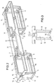
- Fig. 4 shows a view of the runner 8 in the direction of Arrow IV in Fig. 2, wherein the left support leg with the associated bracket 11 is partially broken. in this connection the deep-drawn reinforcement fillet 7 can be clearly seen, with each support foot 6 from the inner Side wall 13 extends into the support part 21.
- the Side walls 9, 13 of the support feet 6 are directed inwards, slightly tapered to the largest possible Stability to maintain easy stackability.
- the bottom part 18 of the support feet 6 can be on the underside with a non-slip covering, not shown, e.g. one Hardboard with a rough surface facing downwards be provided.
- a non-slip covering not shown, e.g. one Hardboard with a rough surface facing downwards be provided.
- there is Support part 21 in the area of the support feet 6 each a striped edge element.
- the striped Edge element is created in an overlapping manner during formation the support feet 6.
- the significantly overlapping strip-like edge elements can be shortened in length and their overlapping ends with each other be connected, welded or poisoned.
- the support feet 6 form in this way both in a horizontal Level as well as one in a vertical level closed frame so that the support feet 6 to a high degree can also absorb shear forces.
- the steel sheets used for the runners 8 preferably have a sheet thickness of approx. 3 to 4 mm.
- the platen 4, the runners 8 can be form-fitting on their underside take up.
- a snap connection is preferred used, for example, the side edges of the Edge element 19 of the runner 8 engages, whereby the runners 8 held in the correct position by the support plate 4 become.
- the runners 8 are also with mounting holes 26 provided that allow the skids 8 in addition to screw with the platen 4.
Landscapes
- Engineering & Computer Science (AREA)
- Mechanical Engineering (AREA)
- Pallets (AREA)
- Control And Other Processes For Unpacking Of Materials (AREA)
- Crystals, And After-Treatments Of Crystals (AREA)
- Transition And Organic Metals Composition Catalysts For Addition Polymerization (AREA)
Description
- Fig. 1
- eine perspektivische Darstellung einer Palette im ½-Euroformat,
- Fig. 2
- eine perspektivische Ansicht einer Kufe mit zwei Stützfüßen,
- Fig. 3
- eine Ansicht der Kufe in Richtung des Pfeils III in Fig. 2,
- Fig. 4
- eine Ansicht der Kufe in Richtung des Pfeils IV in Fig. 2, und
- Fig. 5
- eine Draufsicht auf die Kufe in Richtung des Pfeils V in Fig. 2.
Claims (10)
- Warenträger-System mit aufeinander stapelbaren Paletten (2) mit jeweils einer Auflageplatte (4) und mit mehreren modular auswechselbaren Kufen (8), wobei jede Kufe (8) ein Auflageteil (21) und mindestens zwei Stützfüße (6) und die Auflageplatte (4) Aussparungen (5) zur Aufnahme der Stützfüße (6) aufeinander gestapelter Paletten aufweist,
dadurch gekennzeichnet, daß jeder Stützfuß (6) an den Übergangsstellen zu dem Auflageteil (21) und/oder zu einem bodenparallelen Bodenteil (18) mindestens eine tiefgezogene Verstärkungskehle (3,7) aufweist, und daß jeder Stützfuß (6) einen U-förmigen Bügel (11) aufweist, wobei der mittlere Schenkel (14) des U-förmigen Bügels (11) bündig abschließt mit der Oberfläche der Auflageplatte (4) und die Stützfüße (6) einen dem Bügel (11) angepaßten, in Längsrichtung des Bodenteils (18) verlaufenden Schlitz (16) aufweisen. - Warenträger-System nach Anspruche 1, dadurch gekennzeichnet, daß jede Kufe (8) zwei Stützfüße (6) aus zwei Seitenwänden (9,13) und einem Bodenteil (18) aufweist, die jeweils eine Gabelöffnung (10) bilden und wobei jeder Stützfuß (6) nach innen gerichtete tiefgezogene Verstärkungskehlen (3) aufweist, die sich von den Seitenwänden (9,13) bis in das Bodenteil (18) erstrecken.
- Warenträger-System nach Anspruch 2, dadurch gekennzeichnet, daß die Kufen (8) nach unten gerichtete tiefgezogene Verstärkungskehlen (7) aufweist, die sich von den inneren Seitenwänden (13) der gegenüberliegenden Stützfüße (6) bis in den Auflageteil (21) erstrecken.
- Warenträger-System nach einem der Ansprüche 1 bis 3, dadurch gekennzeichnet, daß die Kufen (8) aus einem Stahlblechstreifen hergestellt sind.
- Warenträger-System nach einem der Ansprüche 2 bis 4, dadurch gekennzeichnet, daß die Seitenwände (9,13) der Stützfüße (6) nach innen gerichtet, konisch geneigt sind.
- Warenträger-System nach einem der Ansprüche 2 bis 5, dadurch gekennzeichnet, daß die Seitenwände (9,13) der Stützfüße zum Bodenteil (18) gerichtet, konisch zulaufen.
- Warenträger-System nach einem der Ansprüche 2 bis 6, dadurch gekennzeichnet, daß das Auflageteil (21) der Kufe (8) ein nach oben gerichtetes Randelement (19) aufweist, das gemeinsam mit den äußeren Seitenwänden (9) der Stützfüße (6) vertikal zur Auflageplatte (4) hin absteht und an der Oberseite der Auflageplatte (4) endet.
- Warenträger-System nach einem der Ansprüche 1 bis 7, dadurch gekennzeichnet, daß der nach außen gerichtete seitliche Schenkel (15) des U-förmigen Bügels (11) in das Randelement (19) eingehängt ist und der nach innen gerichtete seitliche Schenkel (17) des U-förmigen Bügels (11) auf dem Auflageteil (21) befestigt ist.
- Warenträger-System nach einem der Ansprüche 1 bis 8, dadurch gekennzeichnet, daß die Kufe (8) zwei parallel verlaufende Verstärkungssicken oder -rippen (12) aufweist, die sich von dem Auflageteil (21) bis in den Bereich der Seitenwände (9,13) der Stützfüße (6) erstrecken.
- Warenträger-System nach einem der Ansprüche 1 bis 9, dadurch gekennzeichnet, daß die Paletten (2) aus 6-Fuß-½-Euroformatpaletten bestehen.
Applications Claiming Priority (2)
| Application Number | Priority Date | Filing Date | Title |
|---|---|---|---|
| DE29715837U | 1997-09-04 | ||
| DE29715837U DE29715837U1 (de) | 1997-09-04 | 1997-09-04 | Warenträger-System |
Publications (3)
| Publication Number | Publication Date |
|---|---|
| EP0900740A1 EP0900740A1 (de) | 1999-03-10 |
| EP0900740B1 EP0900740B1 (de) | 2002-01-30 |
| EP0900740B9 true EP0900740B9 (de) | 2002-10-02 |
Family
ID=8045497
Family Applications (1)
| Application Number | Title | Priority Date | Filing Date |
|---|---|---|---|
| EP98116716A Expired - Lifetime EP0900740B9 (de) | 1997-09-04 | 1998-09-03 | Warenträger-System II |
Country Status (3)
| Country | Link |
|---|---|
| EP (1) | EP0900740B9 (de) |
| AT (1) | ATE212597T1 (de) |
| DE (2) | DE29715837U1 (de) |
Family Cites Families (4)
| Publication number | Priority date | Publication date | Assignee | Title |
|---|---|---|---|---|
| US3120825A (en) * | 1962-05-28 | 1964-02-11 | Associated Box Corp | Platform |
| US3172374A (en) * | 1963-06-28 | 1965-03-09 | Stanray Corp | Pallets |
| FR2611656B1 (fr) * | 1987-02-20 | 1989-07-13 | Brambles Holdings Ltd | Conteneur grillage destine au transport et au stockage de marchandises |
| DE9310010U1 (de) * | 1993-07-06 | 1993-08-26 | Indupal, Kunststoff- und Display-Paletten GmbH, 50259 Pulheim | Warenträger-System |
-
1997
- 1997-09-04 DE DE29715837U patent/DE29715837U1/de not_active Expired - Lifetime
-
1998
- 1998-09-03 DE DE59802947T patent/DE59802947D1/de not_active Expired - Lifetime
- 1998-09-03 EP EP98116716A patent/EP0900740B9/de not_active Expired - Lifetime
- 1998-09-03 AT AT98116716T patent/ATE212597T1/de not_active IP Right Cessation
Also Published As
| Publication number | Publication date |
|---|---|
| DE29715837U1 (de) | 1999-01-14 |
| DE59802947D1 (de) | 2002-03-14 |
| ATE212597T1 (de) | 2002-02-15 |
| EP0900740B1 (de) | 2002-01-30 |
| EP0900740A1 (de) | 1999-03-10 |
Similar Documents
| Publication | Publication Date | Title |
|---|---|---|
| EP0919483B1 (de) | Kunststoffpalette | |
| DE2554210C2 (de) | Doppeldeckpalette aus Kunststoff | |
| DE10392503T5 (de) | Palette | |
| EP0000356A1 (de) | Stapelbare Flachpalette | |
| EP0584133B1 (de) | Kunststoff-palette | |
| EP3093250B1 (de) | Abstandselement für eine transportpalette sowie transportpalette | |
| DE29908219U1 (de) | Palette mit einer Stützstruktur | |
| EP0669258B1 (de) | Teilpalette | |
| EP0521478B1 (de) | Warenträger-System mit aufeinanderstapelbaren Paletten | |
| EP0900740B9 (de) | Warenträger-System II | |
| EP0912408B1 (de) | Distanzstück sowie palette mit einem distanzstück | |
| DE4111497A1 (de) | Stapelvorrichtung fuer paletten | |
| EP2592010A1 (de) | Palette | |
| EP0572946B1 (de) | Kunststoffpalette | |
| EP0900739B1 (de) | Warenträger-System I | |
| DE9310010U1 (de) | Warenträger-System | |
| CH673992A5 (de) | ||
| DE4209719A1 (de) | Warentraeger-system | |
| WO2007073729A1 (de) | Transportkarre und transportpalette oder transportbehältnis hierfür | |
| WO1989006625A1 (en) | Pallet constructed without nails | |
| EP0846624B1 (de) | Kunststoffpalette mit elastischen Füssen | |
| EP3521190A1 (de) | Transportsystem mit palette und plattenelement | |
| DE9314468U1 (de) | Palette aus zwei gleichen Teilen | |
| EP2112081A1 (de) | Teilpalette | |
| DE29710160U1 (de) | Kunststoffpalette mit elastischen Füßen |
Legal Events
| Date | Code | Title | Description |
|---|---|---|---|
| PUAI | Public reference made under article 153(3) epc to a published international application that has entered the european phase |
Free format text: ORIGINAL CODE: 0009012 |
|
| AK | Designated contracting states |
Kind code of ref document: A1 Designated state(s): AT BE CH DE DK FR GB IT LI NL |
|
| AX | Request for extension of the european patent |
Free format text: AL;LT;LV;MK;RO;SI |
|
| 17P | Request for examination filed |
Effective date: 19990910 |
|
| AKX | Designation fees paid |
Free format text: AT BE CH DE DK FR GB IT LI NL |
|
| 17Q | First examination report despatched |
Effective date: 20000216 |
|
| GRAG | Despatch of communication of intention to grant |
Free format text: ORIGINAL CODE: EPIDOS AGRA |
|
| RAP1 | Party data changed (applicant data changed or rights of an application transferred) |
Owner name: SCHUMACHER, MARIE-THERESE Owner name: ZIEGLER, KURT |
|
| RIN1 | Information on inventor provided before grant (corrected) |
Inventor name: ZIEGLER, KURT |
|
| GRAG | Despatch of communication of intention to grant |
Free format text: ORIGINAL CODE: EPIDOS AGRA |
|
| GRAH | Despatch of communication of intention to grant a patent |
Free format text: ORIGINAL CODE: EPIDOS IGRA |
|
| RAP1 | Party data changed (applicant data changed or rights of an application transferred) |
Owner name: SCHUMACHER, MARIE-THERESE |
|
| GRAH | Despatch of communication of intention to grant a patent |
Free format text: ORIGINAL CODE: EPIDOS IGRA |
|
| GRAA | (expected) grant |
Free format text: ORIGINAL CODE: 0009210 |
|
| REG | Reference to a national code |
Ref country code: GB Ref legal event code: IF02 |
|
| AK | Designated contracting states |
Kind code of ref document: B1 Designated state(s): AT BE CH DE DK FR GB IT LI NL |
|
| PG25 | Lapsed in a contracting state [announced via postgrant information from national office to epo] |
Ref country code: IT Free format text: LAPSE BECAUSE OF FAILURE TO SUBMIT A TRANSLATION OF THE DESCRIPTION OR TO PAY THE FEE WITHIN THE PRE;WARNING: LAPSES OF ITALIAN PATENTS WITH EFFECTIVE DATE BEFORE 2007 MAY HAVE OCCURRED AT ANY TIME BEFORE 2007. THE CORRECT EFFECTIVE DATE MAY BE DIFFERENT FROM THE ONE RECORDED.SCRIBED TIME-LIMIT Effective date: 20020130 |
|
| REF | Corresponds to: |
Ref document number: 212597 Country of ref document: AT Date of ref document: 20020215 Kind code of ref document: T |
|
| REG | Reference to a national code |
Ref country code: CH Ref legal event code: EP |
|
| REF | Corresponds to: |
Ref document number: 59802947 Country of ref document: DE Date of ref document: 20020314 |
|
| PG25 | Lapsed in a contracting state [announced via postgrant information from national office to epo] |
Ref country code: DK Free format text: LAPSE BECAUSE OF FAILURE TO SUBMIT A TRANSLATION OF THE DESCRIPTION OR TO PAY THE FEE WITHIN THE PRESCRIBED TIME-LIMIT Effective date: 20020430 |
|
| GBT | Gb: translation of ep patent filed (gb section 77(6)(a)/1977) |
Effective date: 20020430 |
|
| ET | Fr: translation filed | ||
| PG25 | Lapsed in a contracting state [announced via postgrant information from national office to epo] |
Ref country code: GB Free format text: LAPSE BECAUSE OF NON-PAYMENT OF DUE FEES Effective date: 20020903 |
|
| PGFP | Annual fee paid to national office [announced via postgrant information from national office to epo] |
Ref country code: NL Payment date: 20020910 Year of fee payment: 5 Ref country code: BE Payment date: 20020910 Year of fee payment: 5 |
|
| PLBE | No opposition filed within time limit |
Free format text: ORIGINAL CODE: 0009261 |
|
| STAA | Information on the status of an ep patent application or granted ep patent |
Free format text: STATUS: NO OPPOSITION FILED WITHIN TIME LIMIT |
|
| 26N | No opposition filed | ||
| GBPC | Gb: european patent ceased through non-payment of renewal fee |
Effective date: 20020903 |
|
| PG25 | Lapsed in a contracting state [announced via postgrant information from national office to epo] |
Ref country code: BE Free format text: LAPSE BECAUSE OF NON-PAYMENT OF DUE FEES Effective date: 20030930 |
|
| BERE | Be: lapsed |
Owner name: *SCHUMACHER MARIE-THERESE Effective date: 20030930 |
|
| PG25 | Lapsed in a contracting state [announced via postgrant information from national office to epo] |
Ref country code: NL Free format text: LAPSE BECAUSE OF NON-PAYMENT OF DUE FEES Effective date: 20040401 |
|
| NLV4 | Nl: lapsed or anulled due to non-payment of the annual fee |
Effective date: 20040401 |
|
| REG | Reference to a national code |
Ref country code: FR Ref legal event code: ST |
|
| REG | Reference to a national code |
Ref country code: FR Ref legal event code: RN |
|
| REG | Reference to a national code |
Ref country code: FR Ref legal event code: FC |
|
| PGFP | Annual fee paid to national office [announced via postgrant information from national office to epo] |
Ref country code: FR Payment date: 20060922 Year of fee payment: 9 Ref country code: AT Payment date: 20060922 Year of fee payment: 9 |
|
| PGFP | Annual fee paid to national office [announced via postgrant information from national office to epo] |
Ref country code: CH Payment date: 20060925 Year of fee payment: 9 |
|
| REG | Reference to a national code |
Ref country code: CH Ref legal event code: PL |
|
| PG25 | Lapsed in a contracting state [announced via postgrant information from national office to epo] |
Ref country code: AT Free format text: LAPSE BECAUSE OF NON-PAYMENT OF DUE FEES Effective date: 20070903 |
|
| PG25 | Lapsed in a contracting state [announced via postgrant information from national office to epo] |
Ref country code: LI Free format text: LAPSE BECAUSE OF NON-PAYMENT OF DUE FEES Effective date: 20070930 Ref country code: CH Free format text: LAPSE BECAUSE OF NON-PAYMENT OF DUE FEES Effective date: 20070930 |
|
| REG | Reference to a national code |
Ref country code: FR Ref legal event code: ST Effective date: 20080531 |
|
| PG25 | Lapsed in a contracting state [announced via postgrant information from national office to epo] |
Ref country code: FR Free format text: LAPSE BECAUSE OF NON-PAYMENT OF DUE FEES Effective date: 20071001 |
|
| PGFP | Annual fee paid to national office [announced via postgrant information from national office to epo] |
Ref country code: DE Payment date: 20100820 Year of fee payment: 13 |
|
| REG | Reference to a national code |
Ref country code: DE Ref legal event code: R119 Ref document number: 59802947 Country of ref document: DE Effective date: 20130403 |
|
| PG25 | Lapsed in a contracting state [announced via postgrant information from national office to epo] |
Ref country code: DE Free format text: LAPSE BECAUSE OF NON-PAYMENT OF DUE FEES Effective date: 20130403 |