EP0899152B1 - Siège, en particulier pour une troisième rangée de sièges d'un véhicule automobile - Google Patents
Siège, en particulier pour une troisième rangée de sièges d'un véhicule automobile Download PDFInfo
- Publication number
- EP0899152B1 EP0899152B1 EP98115136A EP98115136A EP0899152B1 EP 0899152 B1 EP0899152 B1 EP 0899152B1 EP 98115136 A EP98115136 A EP 98115136A EP 98115136 A EP98115136 A EP 98115136A EP 0899152 B1 EP0899152 B1 EP 0899152B1
- Authority
- EP
- European Patent Office
- Prior art keywords
- seat
- bracket
- seat according
- working position
- pivot
- Prior art date
- Legal status (The legal status is an assumption and is not a legal conclusion. Google has not performed a legal analysis and makes no representation as to the accuracy of the status listed.)
- Expired - Lifetime
Links
Images
Classifications
-
- B—PERFORMING OPERATIONS; TRANSPORTING
- B60—VEHICLES IN GENERAL
- B60N—SEATS SPECIALLY ADAPTED FOR VEHICLES; VEHICLE PASSENGER ACCOMMODATION NOT OTHERWISE PROVIDED FOR
- B60N2/00—Seats specially adapted for vehicles; Arrangement or mounting of seats in vehicles
- B60N2/24—Seats specially adapted for vehicles; Arrangement or mounting of seats in vehicles for particular purposes or particular vehicles
- B60N2/30—Non-dismountable or dismountable seats storable in a non-use position, e.g. foldable spare seats
- B60N2/3002—Non-dismountable or dismountable seats storable in a non-use position, e.g. foldable spare seats back-rest movements
- B60N2/3004—Non-dismountable or dismountable seats storable in a non-use position, e.g. foldable spare seats back-rest movements by rotation only
- B60N2/3009—Non-dismountable or dismountable seats storable in a non-use position, e.g. foldable spare seats back-rest movements by rotation only about transversal axis
- B60N2/3011—Non-dismountable or dismountable seats storable in a non-use position, e.g. foldable spare seats back-rest movements by rotation only about transversal axis the back-rest being hinged on the cushion, e.g. "portefeuille movement"
-
- B—PERFORMING OPERATIONS; TRANSPORTING
- B60—VEHICLES IN GENERAL
- B60N—SEATS SPECIALLY ADAPTED FOR VEHICLES; VEHICLE PASSENGER ACCOMMODATION NOT OTHERWISE PROVIDED FOR
- B60N2/00—Seats specially adapted for vehicles; Arrangement or mounting of seats in vehicles
- B60N2/24—Seats specially adapted for vehicles; Arrangement or mounting of seats in vehicles for particular purposes or particular vehicles
- B60N2/30—Non-dismountable or dismountable seats storable in a non-use position, e.g. foldable spare seats
- B60N2/3038—Cushion movements
- B60N2/304—Cushion movements by rotation only
- B60N2/3045—Cushion movements by rotation only about transversal axis
- B60N2/305—Cushion movements by rotation only about transversal axis the cushion being hinged on the vehicle frame
-
- B—PERFORMING OPERATIONS; TRANSPORTING
- B60—VEHICLES IN GENERAL
- B60N—SEATS SPECIALLY ADAPTED FOR VEHICLES; VEHICLE PASSENGER ACCOMMODATION NOT OTHERWISE PROVIDED FOR
- B60N2/00—Seats specially adapted for vehicles; Arrangement or mounting of seats in vehicles
- B60N2/24—Seats specially adapted for vehicles; Arrangement or mounting of seats in vehicles for particular purposes or particular vehicles
- B60N2/30—Non-dismountable or dismountable seats storable in a non-use position, e.g. foldable spare seats
- B60N2/3038—Cushion movements
- B60N2/3063—Cushion movements by composed movement
- B60N2/3065—Cushion movements by composed movement in a longitudinal-vertical plane
-
- B—PERFORMING OPERATIONS; TRANSPORTING
- B60—VEHICLES IN GENERAL
- B60N—SEATS SPECIALLY ADAPTED FOR VEHICLES; VEHICLE PASSENGER ACCOMMODATION NOT OTHERWISE PROVIDED FOR
- B60N2/00—Seats specially adapted for vehicles; Arrangement or mounting of seats in vehicles
- B60N2/24—Seats specially adapted for vehicles; Arrangement or mounting of seats in vehicles for particular purposes or particular vehicles
- B60N2/30—Non-dismountable or dismountable seats storable in a non-use position, e.g. foldable spare seats
- B60N2/3072—Non-dismountable or dismountable seats storable in a non-use position, e.g. foldable spare seats on a lower level of a multi-level vehicle floor
Definitions
- the invention relates to a seat, in particular for a third row of seats of a motor vehicle, which essentially from a seat part and one with this hinge-like connected back part and consists of a normal position of use suitable for picking up an occupant can be transferred to a non-use position, in which at least the seat part with its rear surface forms an approximately flat loading area with the vehicle floor.
- Such a seat is from one in DE 44 22 920 A1 described seat arrangement for a loading or passenger compartment known.
- This seat has a seat part that articulated with an approximately vertical position of use lockable backrest connected to the vehicle body is.
- For transferring the entire seat into a non-use position is one in the front area of the seat part arranged transverse axis provided, which in a about horizontal level slidable to the rear is.
- To accommodate the movable transverse axis guide rails are provided in the floor area, which arranged on both sides of the seat part and in the longitudinal direction of the motor vehicle are aligned.
- training takes up a lot of space in the floor area of the motor vehicle and is relatively cumbersome in terms of the transfer of the seat to the non-use position.
- the rail guide of the seat part a higher effort in securing the seat in the Use position required.
- the present invention is therefore based on the object the security and handling of a generic To improve the seat with simple means without that more space is required in the floor area of the motor vehicle becomes.
- a lockable lever device with at least one A pair of pivot levers is provided, which is a pivot the seat part by about 180 ° to the front with a simultaneous Relocation by a certain amount allows.
- a pair of swivel levers on both long sides of the seat part provided, the individual pivot levers each with one end on a supporting body of the seat part and with the other end at one with the vehicle floor or the like connected console rotatably attached are.
- the distances between the respective swivel joints and the position of these swivel joints on the base body and on the console are selected and one on the other coordinated that when swiveling the seat forward (in the non-use position) a turning of the seat part and at the same time its shifting backwards in about the original position (similar to the position of use) takes place.
- Another important advantage of the invention is in that a safety device with a seat provided with the seat locking bolt is, the locking bolt in the event of a frontal accident by moving forward into a recess gets to the console and in this way an unwanted Swiveling the seat forward from the position of use prevented.
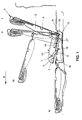
- the seat 1 shows a seat 1 which can be pivoted forward in the direction of travel F and which essentially consists of a seat part 2 and a back part 3.
- the seat part 2 has a supporting base body 5 and the back part 3 has a supporting base body 6, the base bodies 5, 6 being connected to one another in a hinge-like manner about an axis 4.
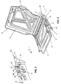
- the seat 1 In the position denoted by I , the seat 1 is in the position of use, in which the back part 3 is connected to the structure via side locks 8 (shown in FIG. 2).
- a lever device 7 which has a pair of pivot levers (pivot levers 9, 10) on each of the two longitudinal sides of the seat part 2.
- the pivot levers 9, 10 are rotatably connected at one end to the base body 5 via a swivel joint 11 or 12 and at the other end via a swivel joint 18 or 19 (not shown) to a bracket 13 .
- the console 13 is designed as a supporting sheet metal part with receiving points 14 (FIG. 3) for articulated connection to the pivot levers 9, 10.
- the console 13 is fixedly connected to the vehicle floor 16 in the area of a floor pan 15 shown in FIG. 1.
- a stop 17 is provided on the console 13, as can be seen in FIG. 2, for Limit the pivoting movement of the front pivot lever 9 .
- the stop 17, which by embossing the sheet material of the console 13 is formed, supports the front pivot lever 9 and thus also the seat part 2 in the normal position of use from.
- the distances between the respective pivots 11, 12, 18, 19 and the positioning of the pivots 11, 12, 18, 19 on the base body 5 and on the bracket 13 are selected and kinematically matched to one another such that when pivoting the in Fig. 1st shown seat 1 forward in the non-use position IV, a pivoting of the seat part 2 by 180 ° and at the same time its shifting backwards takes place approximately in the original position (similar to the use position I ).
- the front pivot lever 9 pivots according to arrow 20 into an approximately horizontal position, while the rear pivot lever 10 about the axis of its lower swivel 19 to approximately the vertical position (position III of the seat 1) and then back again the roughly original position swings.
- the back part 3 is designed to be lockable in the use position I on the console 13.
- an L- shaped recess 22 is provided on the console 13 according to FIG. 3, which has an approximately vertical section A and an approximately horizontal section B , with the horizontal section B forming a locking lug 23 for one with the base body 6 of the back part 3 connected locking bolt 21 a corresponding undercut 24 is formed. Since the locking bolt 21 engages behind the locking lug 23 in the position of use I (FIG. 1) of the seat 1, the seat 1, in particular the seat part 2, cannot be pivoted forward in this position.
- the locking bolt 21 To transfer the seat 1 into the non-use position IV , the locking bolt 21 must first be disengaged from the locking lug 23.
- the locking bolt 21 is arranged parallel and spaced apart from the axis 4 of the hinge-like connection that when the back part 3 is pivoted about the axis 4 into an approximately vertical position II , the locking bolt 21 simultaneously moves into the unlocked position in the region of section A (FIG 3) moves. In this position of the locking bolt 21, the seat part 2 can be transferred together with the back part 3 by swiveling forward into the non-use position IV .
- FIG. 3 A further recess 25 is provided in front of the recess 22 is.
- This recess 25 is arranged such that a deformable between the recess 25 and the recess 22 Web 26 is formed.
- the transfer of the seat 1 into the non-use position IV can, as shown in FIG. 1, be supported by a spring-damper element 27.
- the spring-damper element 27 is connected to the swivel lever 10 and a tab or hole on the bracket 13 in the area of the respective lower swivel joints 18, 19.
Landscapes
- Engineering & Computer Science (AREA)
- Aviation & Aerospace Engineering (AREA)
- Transportation (AREA)
- Mechanical Engineering (AREA)
- Seats For Vehicles (AREA)
Claims (13)
- Siège (1) en particulier pour une troisième rangée de sièges d'un véhicule automobile, comprenant essentiellement une partie siège (2) et une partie dossier (3), qui est liée la première de manière articulée et peut être amenée d'une position d'utilisation (I) normale, adaptée pour recevoir un passager, dans une position de non-utilisation (IV), dans laquelle au moins la partie siège (2) forme avec sa face arrière une surface de chargement sensiblement plane avec le plancher de véhicule (16), caractérisé en ce que pour amener la partie siège (2) dans sa position de non-utilisation (IV), il est prévu un système de biellettes (7) verrouillable avec au moins une paire de biellettes (9, 10), qui permettent un pivotement de la partie siège (2) d'environ 180° vers l'avant avec un déplacement simultané d'une certaine valeur vers l'arrière.
- Siège selon la revendication 1, caractérisé en ce qu'il est prévu sur les deux grands côtés de la partie siège (2), une paire de biellettes (9, 10) dont les différentes biellettes (9, 10) sont fixées avec possibilité de rotation chacune par une extrémité à un corps de base (5) de la partie siège (2) et par l'autre extrémité à une console (13) liée au plancher de véhicule (16) ou similaire.
- Siège selon la revendication 1 ou 2, caractérisé en ce qu'il est prévu sur le système de biellettes (7) un dispositif de sécurité (25, 26) qui dans le cas d'une collision frontale empêche un pivotement intempestif d'au moins la partie siège (2) vers l'avant, hors de la position d'utilisation (I).
- Siège selon une des revendications 1 à 3, caractérisé en ce qu'au moins une biellette (9), dans la position d'utilisation (I) de la partie siège (2), est en appui sur une butée (17) de la console (13).
- Siège selon la revendication 4, caractérisé en ce que la butée (17) est prévue pour limiter le mouvement de pivotement vers l'avant de la biellette (9) antérieure - vu dans la direction de déplacement (F).
- Siège selon une des revendications 2 à 5, caractérisé en ce qu'il est prévu sur le corps de base (5) de la partie siège (2) ou sur un corps de base (6) de la partie dossier (3), au moins une tige de verrouillage (21) orientée transversalement à la direction de déplacement (F) qui, pour l'appui ou le verrouillage d'au moins la partie siège (2) dans la position d'utilisation (I), coopère avec un talon de verrouillage (23) prévue sur la console (13).
- Siège selon la revendication 6, caractérisé en ce que les tiges de verrouillage (21) sont disposées de deux côtés du corps de base (6) de la partie dossier (3), dans la région de la liaison de type charnière avec la partie siège (2).
- Siège selon une des revendications 2 à 7, caractérisé en ce qu'il est prévu sur la console (13), pour former le talon de verrouillage (23), une échancrure (22) en forme de L - vu transversalement à la direction de déplacement (F) - avec une portion (A) sensiblement verticale et une portion (B) sensiblement horizontale, la portion (B) horizontale comportant une contre-dépouille (24) adaptée aux dimensions de la tige de verrouillage (21).
- Siège selon une des revendications 6 à 8, caractérisé en ce qu'au moins une tige de verrouillage (21) disposée sur le corps de base (6) de la partie siège (3), dans la position d'utilisation (I) de la partie dossier (3), s'engage derrière le talon de verrouillage (23) de la console (13).
- Siège selon une des revendications 6 à 9, caractérisé en ce que le dispositif de sécurité comprend une échancrure (25), qui est disposée sur la console de manière telle que soit formée une barrette (26) déformable entre ladite échancrure (25) et la portion (A) de l'échancrure en forme de L (22).
- Siège selon une des revendications 6 à 10, caractérisé en ce que la tige de verrouillage (21) est disposée parallèlement à et à distance de la liaison de type charnière (4), de telle sorte que par pivotement d'un certain angle vers l'avant de la partie dossier (3) autour de l'axe (4) de la liaison de type charnière, la tige de verrouillage ((21) vienne hors de prise d'avec le talon de verrouillage (23).
- Siège selon une des revendications 2 à 11, caractérisé en ce que la console (13) est conformée en pièce d'emboutissage en tôle avec des trous (28) pour sa fixation au plancher de véhicule (16) et des points de montage (14) pour la liaison articulée avec les biellettes (9, 10).
- Siège selon une des revendications 2 à 11, caractérisé en ce qu'une biellette (10) d'au moins une paire de biellettes, pour une manipulation confortable du siège (1) lorsqu'on l'amène au moins dans sa position d'utilisation (I), est reliée à la console (13) par un élément élastique et/ou un élément amortisseur.
Applications Claiming Priority (2)
| Application Number | Priority Date | Filing Date | Title |
|---|---|---|---|
| DE19737304 | 1997-08-27 | ||
| DE19737304A DE19737304A1 (de) | 1997-08-27 | 1997-08-27 | Sitz, insbesondere für eine dritte Sitzreihe eines Kraftfahrzeuges |
Publications (3)
| Publication Number | Publication Date |
|---|---|
| EP0899152A2 EP0899152A2 (fr) | 1999-03-03 |
| EP0899152A3 EP0899152A3 (fr) | 2000-03-29 |
| EP0899152B1 true EP0899152B1 (fr) | 2002-07-24 |
Family
ID=7840313
Family Applications (1)
| Application Number | Title | Priority Date | Filing Date |
|---|---|---|---|
| EP98115136A Expired - Lifetime EP0899152B1 (fr) | 1997-08-27 | 1998-08-12 | Siège, en particulier pour une troisième rangée de sièges d'un véhicule automobile |
Country Status (3)
| Country | Link |
|---|---|
| EP (1) | EP0899152B1 (fr) |
| DE (2) | DE19737304A1 (fr) |
| ES (1) | ES2179405T3 (fr) |
Cited By (2)
| Publication number | Priority date | Publication date | Assignee | Title |
|---|---|---|---|---|
| DE10239112B4 (de) * | 2002-08-27 | 2005-03-10 | Faurecia Autositze Gmbh & Co | Sitz für Kraftfahrzeuge |
| DE102004005969B4 (de) * | 2004-02-06 | 2014-01-09 | GM Global Technology Operations LLC (n. d. Ges. d. Staates Delaware) | Sitz |
Families Citing this family (19)
| Publication number | Priority date | Publication date | Assignee | Title |
|---|---|---|---|---|
| DE19842824B4 (de) * | 1998-09-18 | 2010-09-30 | Volkswagen Ag | Sitzanordnung in einem Fahrzeug |
| DE19929036B4 (de) * | 1999-06-25 | 2011-12-08 | Gm Global Technology Operations Llc (N.D.Ges.D. Staates Delaware) | Verstellbarer Sitz, insbesondere für die zweite oder dritte Sitzreihe eines Kraftfahrzeuges |
| FR2804913B1 (fr) | 2000-02-10 | 2002-05-17 | Faure Bertrand Equipements Sa | Systeme d'agencement modulable des sieges dans un vehicule automobile, notamment pour des sieges de premiere et deuxieme rangee |
| FR2811620B1 (fr) * | 2000-07-12 | 2002-10-25 | Renault | Siege de vehicule automobile equipe d'un siege d'appoint |
| DE10056084B4 (de) * | 2000-11-07 | 2011-02-17 | Volkswagen Ag | Fahrzeugsitz |
| DE10105768B4 (de) * | 2001-02-08 | 2010-07-08 | Volkswagen Ag | Hintersitzanordnung eines Fahrzeuges |
| DE10130430B4 (de) * | 2001-06-23 | 2010-07-22 | GM Global Technology Operations, Inc., Detroit | Anordnung zur Bildung eines ebenen Laderaumes durch Klappen eines Fahrzeugsitzes |
| DE10130425B4 (de) * | 2001-06-23 | 2010-07-08 | GM Global Technology Operations, Inc., Detroit | Anordnung zweier hintereinander angeordneter Fahrzeugsitze zur Bildung eines ebenen Laderaumes |
| DE10148130A1 (de) * | 2001-09-28 | 2003-04-17 | Volkswagen Ag | Sitz, insbesondere Fahrzeugsitz einer hinteren Sitzreihe eines Kraftfahrzeuges |
| ITTO20010990A1 (it) | 2001-10-18 | 2003-04-18 | Italdesign Giugiaro Spa | Sedile ribaltabile per una fila posteriore di un autoveicolo. |
| DE10236490B4 (de) * | 2002-08-09 | 2005-06-23 | Faurecia Autositze Gmbh & Co. Kg | Kraftfahrzeugsitz |
| DE10237398B4 (de) * | 2002-08-09 | 2012-08-16 | Volkswagen Ag | Fahrzeugsitz |
| DE10237612B3 (de) * | 2002-08-16 | 2004-01-22 | Faurecia Autositze Gmbh & Co. Kg | Kraftfahrzeugsitz |
| FR2844228B1 (fr) * | 2002-09-05 | 2005-05-06 | Renault Sa | Siege escamotable comportant des butees d'appui en position d'utilisation |
| DE10244679B4 (de) * | 2002-09-24 | 2005-07-14 | Faurecia Autositze Gmbh & Co. Kg | Kraftfahrzeugsitz |
| DE102004017140B4 (de) * | 2004-04-01 | 2016-11-10 | Volkswagen Ag | Sitzanordnung mit einem wendbaren Sitzteil |
| US7290822B2 (en) | 2005-08-26 | 2007-11-06 | Gm Global Technology Operations, Inc. | Occupant seat system |
| DE102006039994A1 (de) * | 2006-08-25 | 2008-02-28 | GM Global Technology Operations, Inc., Detroit | Sitzanordnung für ein Kraftfahrzeug |
| JP5392283B2 (ja) * | 2011-03-14 | 2014-01-22 | トヨタ自動車株式会社 | 車両用シート |
Family Cites Families (7)
| Publication number | Priority date | Publication date | Assignee | Title |
|---|---|---|---|---|
| US2956837A (en) * | 1957-09-13 | 1960-10-18 | Gen Motors Corp | Seating arrangement for vehicle bodies |
| US3171682A (en) * | 1963-09-23 | 1965-03-02 | Gen Motors Corp | Folding vehicle seats |
| FR2411105A1 (fr) * | 1977-12-09 | 1979-07-06 | Peugeot | Siege transformable perfectionne pour vehicules automobiles |
| DE2843667C3 (de) * | 1978-10-06 | 1981-08-13 | Daimler-Benz Ag, 7000 Stuttgart | Sitzanordnung, insbesondere Notsitzanordnung für einen Mehrzweck-Kraftwagen |
| DE4422920A1 (de) * | 1994-06-30 | 1996-01-04 | Opel Adam Ag | Sitzanordnung, insbesondere für den Lade- bzw. Fahrgastraum eines Kraftfahrzeuges |
| IT1279575B1 (it) * | 1995-05-30 | 1997-12-16 | Fiat Auto Spa | Sedile posteriore scorrevole perfezionato, particolarmente per un autoveicolo. |
| DE19616070C2 (de) * | 1996-04-23 | 1998-03-19 | Keiper Recaro Gmbh Co | Kraftfahrzeugsitz |
-
1997
- 1997-08-27 DE DE19737304A patent/DE19737304A1/de not_active Withdrawn
-
1998
- 1998-08-12 EP EP98115136A patent/EP0899152B1/fr not_active Expired - Lifetime
- 1998-08-12 ES ES98115136T patent/ES2179405T3/es not_active Expired - Lifetime
- 1998-08-12 DE DE59804859T patent/DE59804859D1/de not_active Expired - Lifetime
Cited By (2)
| Publication number | Priority date | Publication date | Assignee | Title |
|---|---|---|---|---|
| DE10239112B4 (de) * | 2002-08-27 | 2005-03-10 | Faurecia Autositze Gmbh & Co | Sitz für Kraftfahrzeuge |
| DE102004005969B4 (de) * | 2004-02-06 | 2014-01-09 | GM Global Technology Operations LLC (n. d. Ges. d. Staates Delaware) | Sitz |
Also Published As
| Publication number | Publication date |
|---|---|
| EP0899152A3 (fr) | 2000-03-29 |
| DE19737304A1 (de) | 1999-03-04 |
| EP0899152A2 (fr) | 1999-03-03 |
| ES2179405T3 (es) | 2003-01-16 |
| DE59804859D1 (de) | 2002-08-29 |
Similar Documents
| Publication | Publication Date | Title |
|---|---|---|
| EP0899152B1 (fr) | Siège, en particulier pour une troisième rangée de sièges d'un véhicule automobile | |
| EP0689954B1 (fr) | Aménagement de siège, notamment pour le compartiment de chargement ou de passenger d'un véhicule automobile | |
| DE19533932C2 (de) | Sitz, insbesondere Fondsitz für Kraftfahrzeuge | |
| DE7808586U1 (de) | Fahrzeugsitz | |
| DE3546147A1 (de) | Ruecksitzpolster in einem kraftfahrzeug | |
| DE102012112525A1 (de) | Nutzfahrzeugsitz mit doppelarretierbarem Querschlittenteil | |
| DE4012860A1 (de) | Fahrzeugsitz, insbesondere kraftfahrzeugsitz | |
| DE10012590B4 (de) | Vor einem Laderaum eines Kraftfahrzeuges angeordnete Sitzanordnung | |
| DE102007036450B3 (de) | Fahrzeugsitz, insbesondere Kraftfahrzeugsitz | |
| DE4417491C2 (de) | Fanghaken zur lösbaren Verriegelung der mit dem Sitzteil eines Fahrzeugsitzes vorschwenkbar verbundenen Rückenlehne | |
| EP1329355A1 (fr) | Siège modulaire | |
| DE602005006046T2 (de) | Fahrzeugsitz und mit diesem Sitz ausgerüstetes Fahrzeug. | |
| DE102012205485B4 (de) | Entriegelungsvorrichtung für einen Fahrzeugsitz mit Einstiegserleichterungsfunktionalität und Verfahren zum Betrieb einer Entriegelungsvorrichtung | |
| DE3518949A1 (de) | Kraftfahrzeugsitz | |
| EP1604863B1 (fr) | Dispositif pour maintenir le dossier d'un siège de véhicule automobile | |
| DE69911278T2 (de) | Heckteilaufbau eines Kraftfahrzeuges | |
| DE102007012429A1 (de) | Kraftfahrzeugsitz | |
| DE69814836T2 (de) | Verstärkungselemente für ein fahrzeug | |
| DE102018109611B4 (de) | Kopfstütze | |
| EP1627768A2 (fr) | Siège pliable en particulier pour véhicules automobiles | |
| EP1615795B1 (fr) | Dispositif de guidage longitudinal pour un siege de vehicule automobile | |
| DE19702258C2 (de) | Sitzanordnung, insbesondere für den Laderaum eines Kraftfahrzeuges | |
| DE60010123T3 (de) | Verstellbarer Sitz für Krafftfahrzeug | |
| DE2640895C3 (de) | Schlafliege für das Fahrerhaus eines Kraftfahrzeuges | |
| DE202005020672U1 (de) | Fahrzeugsitz, insbesondere Kraftfahrzeugsitz |
Legal Events
| Date | Code | Title | Description |
|---|---|---|---|
| PUAI | Public reference made under article 153(3) epc to a published international application that has entered the european phase |
Free format text: ORIGINAL CODE: 0009012 |
|
| AK | Designated contracting states |
Kind code of ref document: A2 Designated state(s): DE ES FR GB |
|
| AX | Request for extension of the european patent |
Free format text: AL;LT;LV;MK;RO;SI |
|
| PUAL | Search report despatched |
Free format text: ORIGINAL CODE: 0009013 |
|
| AK | Designated contracting states |
Kind code of ref document: A3 Designated state(s): AT BE CH CY DE DK ES FI FR GB GR IE IT LI LU MC NL PT SE |
|
| AX | Request for extension of the european patent |
Free format text: AL;LT;LV;MK;RO;SI |
|
| RIC1 | Information provided on ipc code assigned before grant |
Free format text: 7B 60N 2/36 A, 7B 60N 2/30 B |
|
| 17P | Request for examination filed |
Effective date: 20000822 |
|
| AKX | Designation fees paid |
Free format text: DE ES FR GB |
|
| GRAG | Despatch of communication of intention to grant |
Free format text: ORIGINAL CODE: EPIDOS AGRA |
|
| GRAG | Despatch of communication of intention to grant |
Free format text: ORIGINAL CODE: EPIDOS AGRA |
|
| GRAG | Despatch of communication of intention to grant |
Free format text: ORIGINAL CODE: EPIDOS AGRA |
|
| GRAH | Despatch of communication of intention to grant a patent |
Free format text: ORIGINAL CODE: EPIDOS IGRA |
|
| 17Q | First examination report despatched |
Effective date: 20011220 |
|
| GRAH | Despatch of communication of intention to grant a patent |
Free format text: ORIGINAL CODE: EPIDOS IGRA |
|
| GRAA | (expected) grant |
Free format text: ORIGINAL CODE: 0009210 |
|
| AK | Designated contracting states |
Kind code of ref document: B1 Designated state(s): DE ES FR GB |
|
| REG | Reference to a national code |
Ref country code: GB Ref legal event code: FG4D Free format text: NOT ENGLISH |
|
| REF | Corresponds to: |
Ref document number: 59804859 Country of ref document: DE Date of ref document: 20020829 |
|
| GBT | Gb: translation of ep patent filed (gb section 77(6)(a)/1977) |
Effective date: 20020919 |
|
| REG | Reference to a national code |
Ref country code: ES Ref legal event code: FG2A Ref document number: 2179405 Country of ref document: ES Kind code of ref document: T3 |
|
| ET | Fr: translation filed | ||
| PLBE | No opposition filed within time limit |
Free format text: ORIGINAL CODE: 0009261 |
|
| STAA | Information on the status of an ep patent application or granted ep patent |
Free format text: STATUS: NO OPPOSITION FILED WITHIN TIME LIMIT |
|
| 26N | No opposition filed |
Effective date: 20030425 |
|
| REG | Reference to a national code |
Ref country code: GB Ref legal event code: 732E Free format text: REGISTERED BETWEEN 20090219 AND 20090225 |
|
| REG | Reference to a national code |
Ref country code: GB Ref legal event code: 732E Free format text: REGISTERED BETWEEN 20090305 AND 20090311 |
|
| REG | Reference to a national code |
Ref country code: GB Ref legal event code: 732E Free format text: REGISTERED BETWEEN 20091029 AND 20091104 |
|
| REG | Reference to a national code |
Ref country code: GB Ref legal event code: 732E Free format text: REGISTERED BETWEEN 20091105 AND 20091111 |
|
| REG | Reference to a national code |
Ref country code: DE Ref legal event code: R081 Ref document number: 59804859 Country of ref document: DE Owner name: GM GLOBAL TECHNOLOGY OPERATIONS LLC (N. D. GES, US Free format text: FORMER OWNER: GM GLOBAL TECHNOLOGY OPERATIONS, INC., DETROIT, MICH., US Effective date: 20110323 Ref country code: DE Ref legal event code: R081 Ref document number: 59804859 Country of ref document: DE Owner name: GM GLOBAL TECHNOLOGY OPERATIONS LLC (N. D. GES, US Free format text: FORMER OWNER: GM GLOBAL TECHNOLOGY OPERATIONS, INC., DETROIT, US Effective date: 20110323 |
|
| PGFP | Annual fee paid to national office [announced via postgrant information from national office to epo] |
Ref country code: GB Payment date: 20120808 Year of fee payment: 15 |
|
| PGFP | Annual fee paid to national office [announced via postgrant information from national office to epo] |
Ref country code: DE Payment date: 20120808 Year of fee payment: 15 Ref country code: ES Payment date: 20120907 Year of fee payment: 15 Ref country code: FR Payment date: 20120823 Year of fee payment: 15 |
|
| GBPC | Gb: european patent ceased through non-payment of renewal fee |
Effective date: 20130812 |
|
| PG25 | Lapsed in a contracting state [announced via postgrant information from national office to epo] |
Ref country code: DE Free format text: LAPSE BECAUSE OF NON-PAYMENT OF DUE FEES Effective date: 20140301 |
|
| REG | Reference to a national code |
Ref country code: DE Ref legal event code: R119 Ref document number: 59804859 Country of ref document: DE Effective date: 20140301 |
|
| REG | Reference to a national code |
Ref country code: FR Ref legal event code: ST Effective date: 20140430 |
|
| PG25 | Lapsed in a contracting state [announced via postgrant information from national office to epo] |
Ref country code: GB Free format text: LAPSE BECAUSE OF NON-PAYMENT OF DUE FEES Effective date: 20130812 |
|
| PG25 | Lapsed in a contracting state [announced via postgrant information from national office to epo] |
Ref country code: FR Free format text: LAPSE BECAUSE OF NON-PAYMENT OF DUE FEES Effective date: 20130902 |
|
| PG25 | Lapsed in a contracting state [announced via postgrant information from national office to epo] |
Ref country code: ES Free format text: LAPSE BECAUSE OF NON-PAYMENT OF DUE FEES Effective date: 20130813 |