EP0898535B1 - Wagenkasten eines schienenfahrzeuges - Google Patents
Wagenkasten eines schienenfahrzeuges Download PDFInfo
- Publication number
- EP0898535B1 EP0898535B1 EP97923789A EP97923789A EP0898535B1 EP 0898535 B1 EP0898535 B1 EP 0898535B1 EP 97923789 A EP97923789 A EP 97923789A EP 97923789 A EP97923789 A EP 97923789A EP 0898535 B1 EP0898535 B1 EP 0898535B1
- Authority
- EP
- European Patent Office
- Prior art keywords
- coach body
- vehicle
- body according
- modules
- horizontal
- Prior art date
- Legal status (The legal status is an assumption and is not a legal conclusion. Google has not performed a legal analysis and makes no representation as to the accuracy of the status listed.)
- Expired - Lifetime
Links
- 229920002430 Fibre-reinforced plastic Polymers 0.000 claims abstract description 16
- 239000011151 fibre-reinforced plastic Substances 0.000 claims abstract description 16
- 239000010410 layer Substances 0.000 claims description 12
- 238000009434 installation Methods 0.000 claims description 5
- 238000004026 adhesive bonding Methods 0.000 claims description 4
- 239000012792 core layer Substances 0.000 claims description 4
- 239000011521 glass Substances 0.000 claims description 4
- 238000005452 bending Methods 0.000 claims description 3
- 238000005516 engineering process Methods 0.000 claims description 3
- 230000007704 transition Effects 0.000 claims description 3
- OKTJSMMVPCPJKN-UHFFFAOYSA-N Carbon Chemical compound [C] OKTJSMMVPCPJKN-UHFFFAOYSA-N 0.000 claims description 2
- 229920003235 aromatic polyamide Polymers 0.000 claims description 2
- 229910052799 carbon Inorganic materials 0.000 claims description 2
- 230000000295 complement effect Effects 0.000 claims description 2
- 239000003822 epoxy resin Substances 0.000 claims description 2
- LNEPOXFFQSENCJ-UHFFFAOYSA-N haloperidol Chemical compound C1CC(O)(C=2C=CC(Cl)=CC=2)CCN1CCCC(=O)C1=CC=C(F)C=C1 LNEPOXFFQSENCJ-UHFFFAOYSA-N 0.000 claims description 2
- 238000002347 injection Methods 0.000 claims description 2
- 239000007924 injection Substances 0.000 claims description 2
- 239000011159 matrix material Substances 0.000 claims description 2
- 238000005192 partition Methods 0.000 claims description 2
- 239000005011 phenolic resin Substances 0.000 claims description 2
- 229920000647 polyepoxide Polymers 0.000 claims description 2
- 229920005989 resin Polymers 0.000 claims description 2
- 239000011347 resin Substances 0.000 claims description 2
- 229920006337 unsaturated polyester resin Polymers 0.000 claims description 2
- 229920001567 vinyl ester resin Polymers 0.000 claims description 2
- 241000531908 Aramides Species 0.000 claims 1
- 230000015572 biosynthetic process Effects 0.000 claims 1
- 238000000034 method Methods 0.000 claims 1
- 239000007787 solid Substances 0.000 claims 1
- 238000004519 manufacturing process Methods 0.000 description 7
- 230000005540 biological transmission Effects 0.000 description 3
- 230000002787 reinforcement Effects 0.000 description 3
- 229910000831 Steel Inorganic materials 0.000 description 2
- 238000010276 construction Methods 0.000 description 2
- 239000000463 material Substances 0.000 description 2
- 239000002184 metal Substances 0.000 description 2
- 230000003068 static effect Effects 0.000 description 2
- 239000010959 steel Substances 0.000 description 2
- 241000264877 Hippospongia communis Species 0.000 description 1
- 240000007182 Ochroma pyramidale Species 0.000 description 1
- 239000004760 aramid Substances 0.000 description 1
- 239000004566 building material Substances 0.000 description 1
- 230000007797 corrosion Effects 0.000 description 1
- 238000005260 corrosion Methods 0.000 description 1
- 239000000835 fiber Substances 0.000 description 1
- 239000002657 fibrous material Substances 0.000 description 1
- 239000000945 filler Substances 0.000 description 1
- 239000006260 foam Substances 0.000 description 1
- 238000009413 insulation Methods 0.000 description 1
- 238000012423 maintenance Methods 0.000 description 1
- 238000010422 painting Methods 0.000 description 1
- 229920001568 phenolic resin Polymers 0.000 description 1
- 239000012783 reinforcing fiber Substances 0.000 description 1
- 238000000926 separation method Methods 0.000 description 1
Images

Classifications
-
- B—PERFORMING OPERATIONS; TRANSPORTING
- B61—RAILWAYS
- B61D—BODY DETAILS OR KINDS OF RAILWAY VEHICLES
- B61D17/00—Construction details of vehicle bodies
- B61D17/04—Construction details of vehicle bodies with bodies of metal; with composite, e.g. metal and wood body structures
-
- B—PERFORMING OPERATIONS; TRANSPORTING
- B61—RAILWAYS
- B61D—BODY DETAILS OR KINDS OF RAILWAY VEHICLES
- B61D17/00—Construction details of vehicle bodies
- B61D17/04—Construction details of vehicle bodies with bodies of metal; with composite, e.g. metal and wood body structures
- B61D17/08—Sides
-
- B—PERFORMING OPERATIONS; TRANSPORTING
- B61—RAILWAYS
- B61D—BODY DETAILS OR KINDS OF RAILWAY VEHICLES
- B61D17/00—Construction details of vehicle bodies
- B61D17/04—Construction details of vehicle bodies with bodies of metal; with composite, e.g. metal and wood body structures
- B61D17/043—Construction details of vehicle bodies with bodies of metal; with composite, e.g. metal and wood body structures connections between superstructure sub-units
- B61D17/045—The sub-units being construction modules
-
- Y—GENERAL TAGGING OF NEW TECHNOLOGICAL DEVELOPMENTS; GENERAL TAGGING OF CROSS-SECTIONAL TECHNOLOGIES SPANNING OVER SEVERAL SECTIONS OF THE IPC; TECHNICAL SUBJECTS COVERED BY FORMER USPC CROSS-REFERENCE ART COLLECTIONS [XRACs] AND DIGESTS
- Y02—TECHNOLOGIES OR APPLICATIONS FOR MITIGATION OR ADAPTATION AGAINST CLIMATE CHANGE
- Y02T—CLIMATE CHANGE MITIGATION TECHNOLOGIES RELATED TO TRANSPORTATION
- Y02T30/00—Transportation of goods or passengers via railways, e.g. energy recovery or reducing air resistance
Definitions
- the invention relates to a car body of a rail vehicle, which essentially consists of horizontal and vertical walls, the horizontal Walls forming a floor and a roof serve and the vertical, especially side walls walls forming the installation of at least one window and cutouts that allow entry doors.
- DE-B-1 158 541 also includes a car body a rail vehicle of the prior art, which in essentially from horizontal and vertical walls consists.
- the horizontal walls serve that Form a floor as well as a roof.
- the vertical Contain walls that form in particular side walls Cutouts that include the installation of windows and entry doors allow.
- the horizontal and vertical walls are halved in cross-section to the vehicle's longitudinal axis Modules made of fiber-reinforced plastic, these modules each have a length that corresponds to the length of the car body. This is very large devices required for manufacture (see 13 of DE-B-1 158 541).
- the invention has for its object a car body of the generic type as far as possible simple, inexpensive manufacture and a reduction train the vehicle mass, the Car body a high degree of flexibility in the design of the rail vehicle.
- the advantages which can be achieved with the object according to the invention consist in particular in the following:
- the half modules allow a high degree of flexibility in vehicle design, in which any desired configuration of a car body can be realized in its longitudinal and transverse directions.
- the relatively short half-modules made of fiber-reinforced plastic are simple and inexpensive to manufacture, and compact, handy devices can be used for production.
- To save the manufacturing costs of the car body the fact that an interior lining of the modules and a treatment of the outer surfaces can be dispensed with by applying a filler layer over a large area.
- the vehicle mass is also reduced, which also saves energy costs during driving.
- the modules made of fiber-reinforced plastic are free from corrosion and therefore require no maintenance.
- 1 and 2 is the driven or unpowered chassis 10 supported car body composed of relatively short half modules 3, each made of fiber-reinforced plastic.
- the Floor and roof of the car body are horizontal Walls 1 and the side walls by vertical Walls 2 of these modules 3 are formed.
- Two each of these Completely arranged half modules 3, the their meeting in the vehicle center 4 horizontal walls 1 are connected to transmit power, represent a longitudinal section of the car body.
- the length of the car body results from power transmission Connect a corresponding number of the aforementioned Longitudinal sections at their rotating in the vehicle transverse direction Joints 5.
- the vertical walls 2 contain cutouts 2a which the installation of a window - for example in the form of a 4 used glass pane 8 - or one Allow entry door.
- the section 2a in the vertical Wall 2 for the installation of an entrance door can through a recess (not shown) within the horizontal wall 1 can be added to there To accommodate the step assembly.
- Window modules 3.2 and door modules 3.3 can optionally full-surface modules 3.1 and a module 3.4 as Transition to a joint of a train set used become.
- a shown headboard 9 which is also made of fiber reinforced Plastic can be formed by a second joint module 3.4 or vice versa through the joint module 3.4 to replace a second head module 9.
- Modules 3.1 to 3.4 described above are any desired Configuration of a car body in the longitudinal direction and in Transverse direction can be easily realized, for.
- B. can Have only window modules 3.2 on the long side of the car body and the opposite long side two door modules 3.3 in combination with window modules 3.2 included.
- the modules 3 in the area of the roof-side horizontal walls 1 rectangular cavities 3d.
- the 3d cavities and grooves 3e each take the length of the car body continuous belt 7 on, with tensile and compressive forces as well as bending forces can be claimed.
- the Belt 7 can be made of a metal profile or preferably fiber-reinforced plastic with longitudinally oriented Continuous fibers exist and, for example, by Pultrusion can be made.
- In terms of static There is a separation of the body of the car between tensile and compressive loads, which with the help of the continuous Belts 7 are transmitted, and drawers, the modules 3 transmit them.
- the modules 3 an inner layer 3a made of fiber-reinforced plastic, a similar outer layer 3b and one core layer 3c arranged between these layers good properties in terms of heat and sound insulation educated.
- Various are suitable as core layer 3c Light building materials, such as balsa wood, foams, honeycombs.
- the fiber-reinforced plastic contains as a matrix material optionally epoxy resins, unsaturated polyester resins, Vinyl ester resins or phenolic resins.
- a reinforcement material can glass, carbon, aramid and / or other reinforcing fibers are used, whereby the selection of the fiber material according to the respective local load of the modules 3 can address. It understands themselves that the fiber-reinforced plastic each applicable fire protection regulations. For the Production of modules 3 is recommended using injection technology, because it’s smooth, finished inside and out Surfaces are achievable. On a metallic one Car bodies usual interior lining and on large-scale filling of the outer surfaces before painting can therefore be dispensed with.
- Each half module 3 is in its with other modules area to be connected according to the power transmission Joining technology by screwing, riveting and / or gluing designed.
- 3 to 5 are the inner Layer 3a and the outer layer 3b brought together, 3 and 4, one for connecting by Screwing, riveting and gluing usable bending 3f is formed. 5, the connection takes place alone by gluing using a reinforcement bar 3g.
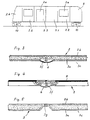
- the joint 5 in the vehicle transverse direction of two longitudinal sections can be identified by one in FIGS. 2 to 4 shown strip 6 are clad, of which in Fig. 2 only a section is shown.
- the in the vehicle transverse direction circumferential joint 5 is due to their Stability at the same time for attaching equipment usable of the vehicle, for example one Partition, a passenger seat or a handrail.
- the cavity covered by the bar 6 in the area of Joint 5 is for receiving supply lines, such as cables and pipes. They can continue half modules 3 not shown shafts for such Supply lines included.
Landscapes
- Engineering & Computer Science (AREA)
- Life Sciences & Earth Sciences (AREA)
- Wood Science & Technology (AREA)
- Mechanical Engineering (AREA)
- Body Structure For Vehicles (AREA)
- Packaging Of Annular Or Rod-Shaped Articles, Wearing Apparel, Cassettes, Or The Like (AREA)
- Passenger Equipment (AREA)
- Vehicle Step Arrangements And Article Storage (AREA)
- Train Traffic Observation, Control, And Security (AREA)
Description
Die hälftigen Module ermöglichen eine hohe Flexibilität bei der Fahrzeuggestaltung, in dem jede gewünschte Konfiguration eines Wagenkastens in dessen Längs- und Querrichtung realisiert werden kann. Die relativ kurzen hälftigen Module aus faserverstärktem Kunststoff sind einfach und kostengünstig herstellbar, wobei kompakte, handliche Einrichtungen für die Produktion verwendet werden können. Zum Einsparen der Herstellungskosten des Wagenkastens trägt bei, daß eine Innenverkleidung der Module und eine Behandlung der Außenflächen durch großflächiges Auftragen einer Spachtelschicht entfallen können. Weiter günstig ergibt sich eine Reduzierung der Fahrzeugmasse, wodurch auch Energiekosten im Fahrbetrieb eingespart werden. Die Module aus faserverstärktem Kunststoff sind frei von Korrosion und damit ohne Wartungsaufwand einzusetzen.
- Fig. 1
- ein Schienenfahrzeug mit einem erfindungsgemäßen Wagenkasten in Seitenansicht,
- Fig. 2
- einen Abschnitt eines Wagenkastens nach der Erfindung in perspektivischer Darstellung,
- Fig. 3
- den Schnitt nach der Linie A-A in Fig. 2,
- Fig. 4
- den Schnitt nach der Linie B-B in Fig. 2,
- Fig. 5
- eine alternative Gestaltung in einem der Fig. 3 ähnlichen Schnitt.
- 1
- horizontale Wandung
- 2
- vertikale Wandung
- 2a
- Ausschnitt für Fenster oder Einstiegstür
- 3
- hälftiges Modul aus faserverstärktem Werkstoff
- 3.1
- vollflächiges Modul
- 3.2
- Modul mit Fensterausschnitt (Fenstermodul)
- 3.3
- Modul mit Türausschnitt (Türmodul)
- 3.4
- Modul als Übergang zu einem Gelenk eines Zugverbandes (Gelenkmodul)
- 3a
- innere Schicht
- 3b
- äußere Schicht
- 3c
- Kernschicht
- 3d
- rechteckförmiger Hohlraum
- 3e
- rechteckförmige Nut
- 3f
- Abwinkelung
- 3g
- Verstärkungsleiste
- 4
- Fahrzeugquermitte
- 5
- Stoßstelle, in Fahrzeugquerrichtung umlaufend
- 6
- Leiste
- 7
- Gurt
- 8
- Glasscheibe
- 9
- Kopfteil
- 10
- Fahrgestell
Claims (12)
- Wagenkasten eines Schienenfahrzeuges, der im wesentlichen aus horizontalen und vertikalen Wandungen (1, 2) besteht, wobei die horizontalen Wandungen (1) dem Bilden eines Bodens sowie eines Daches dienen und die vertikalen, insbesondere Seitenwände bildenden Wandungen (2) den Einbau mindestens eines Fensters und einer Einstiegstür zulassende Ausschnitte (2a) enthalten, wobei die horizontalen und vertikalen Wandungen (1, 2) durch im Schnitt quer zur Fahrzeuglängsachse hälftige Module (3) aus faserverstärktem Kunststoff gebildet sind, wobei jeweils zwei dieser komplementär angeordneten und an ihren in der Fahrzeugquermitte (4) zusammentreffenden horizontalen Wandungen (1) kraftübertragend verbundenen hälftigen Modu e (3 eine Längssektion des Wagenkastens darstellen, dadurch gekennzeichnet, daß die Länge des Wagenkastens durch kraftübertragendes Verbinden einer Anzahl vorgenannter Längssektionen an ihren in Fahrzeugquerrichtung umlaufenden Stoßstellen (5) entsprechend auslegbar ist.
- Wagenkasten nach Anspruch 1, dadurch gekennzeichnet, daß wahlweise lediglich vier Typen der hälftigen Module (3) eingesetzt werden, nämlich ein vollflächiges Modul (3.1), ein Modul (3.2) mit Fensterausschnitt, ein Modul (3.3) mit Türausschnitt und ein Modul (3.4) als Übergang zu einem Gelenk eines Zugverbandes, beispielsweise eines Stadtbahn-Gelenkfahrzeuges.
- Wagenkasten nach Anspruch 1 oder 2, dadurch gekennzeichnet, daß die hälftigen Module (3) aus einer inneren Schicht (3a) und einer äußeren Schicht (3b) sowie einer zwischen diesen Schichten (3a, 3b) angeordneten Kernschicht (3c) mit guten Eigenschaften in bezug auf Wärme- und Schallisolierung gebildet sind, wobei die innere Schicht (3a) und die äußere Schicht (3b) aus faserverstärktem Kunststoff bestehen.
- Wagenkasten nach einem der Ansprüche 1 bis 3, dadurch gekennzeichnet, daß der faserverstärkte Kunststoff als Matrixwerkstoff wahlweise Epoxidharze, ungesättigte Polyesterharze, Vinylesterharze oder Phenolharze enthält.
- Wagenkasten nach einem der Ansprüche 1 bis 4, dadurch gekennzeichnet, daß der faserverstärkte Kunststoff Glas-, Kohlenstoff-, Aramid- und/oder Naturfasern aufweist.
- Wagenkasten nach einem der Ansprüche 1 bis 5, dadurch gekennzeichnet, daß die hälftigen Module (3) in Injektionstechnik hergestellt sind.
- Wagenkasten nach einem der Ansprüche 1 bis 6, dadurch gekennzeichnet, daß jedes hälftige Modul (3) in seinem mit anderen Modulen (3) kraftübertragend zu verbindenden Bereich entsprechend der Fügetechnik durch Schrauben, Nieten und/oder Kleben gestaltet ist.
- Wagenkasten nach einem der Ansprüche 1 bis 7, dadurch gekennzeichnet, daß die in Fahrzeugquerrichtung umlaufende Stoßstelle (5) von zwei Längssektionen durch eine Leiste (6) verkleidet ist.
- Wagenkasten nach einem der Ansprüche 1 bis 8, dadurch gekennzeichnet, daß die in Fahrzeugquerrichtung umlaufende Stoßstelle (5) von zwei Längssektionen zugleich für das Befestigen von Ausstattungsteilen des Fahrzeuges genutzt wird, beispielsweise einer Trennwand, eines Fahrgastsitzes oder einer Haltestange.
- Wagenkasten nach einem der Ansprüche 1 bis 9, dadurch gekennzeichnet, daß die hälftigen Module (3) im Bereich der dachseitigen und/oder der bodenseitigen horizontalen Wandungen (1) rechteckförmige Hohlräume (3d) oder Nuten (3e) aufweisen, die jeweils einen in Länge des Wagenkastens durchlaufenden, mit Zug-, Druck- und Biegekräften beanspruchbaren Gurt (7) aufnehmen.
- Wagenkasten nach Anspruch 10, dadurch gekennzeichnet, daß der Gurt (7) aus faserverstärktem Kunststoff mit in Längsrichtung orientierten Endlosfasern besteht.
- Wagenkasten nach einem der Ansprüche 1 bis 11, dadurch gekennzeichnet, daß die hälftigen Module (3) mit Schächten zur Aufnahme von Versorgungsleitungen, insbesondere Kabeln, versehen sind.
Priority Applications (1)
| Application Number | Priority Date | Filing Date | Title |
|---|---|---|---|
| SI9730038T SI0898535T1 (en) | 1996-05-13 | 1997-05-03 | Coach body of railway vehicle |
Applications Claiming Priority (3)
| Application Number | Priority Date | Filing Date | Title |
|---|---|---|---|
| DE19619212A DE19619212A1 (de) | 1996-05-13 | 1996-05-13 | Wagenkasten eines Schienenfahrzeuges |
| DE19619212 | 1996-05-13 | ||
| PCT/DE1997/000930 WO1997043158A1 (de) | 1996-05-13 | 1997-05-03 | Wagenkasten eines schienenfahrzeuges |
Publications (3)
| Publication Number | Publication Date |
|---|---|
| EP0898535A1 EP0898535A1 (de) | 1999-03-03 |
| EP0898535B1 true EP0898535B1 (de) | 2000-03-01 |
| EP0898535B2 EP0898535B2 (de) | 2003-12-03 |
Family
ID=7794160
Family Applications (1)
| Application Number | Title | Priority Date | Filing Date |
|---|---|---|---|
| EP97923789A Expired - Lifetime EP0898535B2 (de) | 1996-05-13 | 1997-05-03 | Wagenkasten eines schienenfahrzeuges |
Country Status (14)
| Country | Link |
|---|---|
| US (1) | US6227125B1 (de) |
| EP (1) | EP0898535B2 (de) |
| JP (1) | JP2000510071A (de) |
| KR (1) | KR20000010960A (de) |
| CN (1) | CN1216958A (de) |
| AT (1) | ATE190019T1 (de) |
| AU (1) | AU713260B2 (de) |
| CA (1) | CA2253308C (de) |
| CZ (1) | CZ288291B6 (de) |
| DE (2) | DE19619212A1 (de) |
| ES (1) | ES2143865T3 (de) |
| PL (1) | PL329079A1 (de) |
| SK (1) | SK151498A3 (de) |
| WO (1) | WO1997043158A1 (de) |
Families Citing this family (67)
| Publication number | Priority date | Publication date | Assignee | Title |
|---|---|---|---|---|
| DE19643337A1 (de) * | 1996-10-21 | 1998-04-23 | Abb Patent Gmbh | Schienenfahrzeug |
| DE19756439A1 (de) * | 1997-12-18 | 1999-06-24 | Duewag Ag | Wagenkasten eines Schienenfahrzeuges |
| DE19955539A1 (de) * | 1999-11-18 | 2001-05-31 | Siemens Duewag Gmbh | Wagenkasten eines Schienenfahrzeuges zur Personenbeförderung |
| DE10053125A1 (de) * | 2000-10-19 | 2002-05-08 | Daimlerchrysler Rail Systems | Schienenfahrzeug mit modular aufgebautem Wagenkasten |
| US6722287B2 (en) * | 2001-02-09 | 2004-04-20 | Trn Business Trust | Roof assembly and airflow management system for a temperature controlled railway car |
| US6892433B2 (en) * | 2001-02-09 | 2005-05-17 | Trn Business Trust | Manufacturing method of assembling temperature controlled railway car |
| US6871600B2 (en) * | 2001-02-09 | 2005-03-29 | Trn Business Trust | Pultruded panel |
| US7543367B2 (en) * | 2001-02-09 | 2009-06-09 | Trinity Industries, Inc. | Method of assembling a temperature controlled railway car |
| US6575102B2 (en) * | 2001-02-09 | 2003-06-10 | Trn Business Trust | Temperature controlled railway car |
| US7343715B2 (en) * | 2001-05-17 | 2008-03-18 | Toray Industries, Inc. | Sound-proof wall made of FRP, and method of producing the same |
| AU2003266203A1 (en) * | 2002-09-20 | 2004-04-08 | Jupiter Plast A/S | A coach body for a rail vehicle and method for producing the coach body |
| US7478600B2 (en) * | 2003-04-28 | 2009-01-20 | Trinity Industries, Inc. | Temperature controlled railway car |
| US7228805B2 (en) * | 2003-04-28 | 2007-06-12 | Trinity Industries, Inc. | Temperature controlled railway car |
| US20050161975A1 (en) * | 2004-01-23 | 2005-07-28 | Nieminski Brant R. | Modular bus body assembly |
| CN100408403C (zh) * | 2006-03-09 | 2008-08-06 | 中国南车集团南京浦镇车辆厂 | 地铁车辆侧墙 |
| AU2006100802A4 (en) * | 2006-09-19 | 2006-10-19 | Robert Paul Frankham | Modular canopy |
| DE102007050181A1 (de) * | 2007-10-19 | 2009-04-23 | Siemens Ag | Wagenkasten mit Funktionskedern |
| US8025331B2 (en) * | 2008-03-17 | 2011-09-27 | Wabash National, L.P. | Roof assembly for a storage container |
| AT506765B1 (de) * | 2008-04-23 | 2010-02-15 | Siemens Transportation Systems | Modulare nasszelle für ein schienenfahrzeug |
| AU2009261982B2 (en) * | 2008-06-27 | 2014-08-21 | Proterra Operating Company, Inc. | Vehicle battery systems and methods |
| DE102009040164B4 (de) * | 2009-09-04 | 2014-11-20 | Voith Patent Gmbh | Tragkonstruktion für ein Schienenfahrzeug |
| DE102009045202B4 (de) * | 2009-09-30 | 2014-09-11 | Deutsches Zentrum für Luft- und Raumfahrt e.V. | Modularer Wagenkasten |
| CA2718779A1 (en) * | 2009-10-26 | 2011-04-26 | Wabash National, L.P. | Modular storage container |
| BRPI1009739A2 (pt) * | 2010-01-08 | 2016-03-15 | Youzhou Song | veículo de transporte leve. |
| CN101913359A (zh) * | 2010-07-30 | 2010-12-15 | 别道平 | 火车电力自生技术方法 |
| CN102151647B (zh) * | 2011-03-28 | 2013-07-10 | 南车四方车辆有限公司 | 隔音挡板制造方法、隔音挡板及高速列车 |
| DE102011051634A1 (de) * | 2011-07-07 | 2013-01-10 | Bombardier Transportation Gmbh | Konstruktionsverfahren zum Aufbau eines Schienenfahrzeugwagens, Verfahren zur Herstellung eines Schienenfahrzeugwagens, und Schienenfahrzeugfamilie |
| KR101338442B1 (ko) * | 2011-12-08 | 2013-12-10 | 현대자동차주식회사 | 차체 및 이를 성형하는 방법 |
| US8727426B2 (en) * | 2012-03-16 | 2014-05-20 | GM Global Technology Operations LLC | Expandable vehicle system and method of expanding a vehicle |
| ES1076926Y (es) * | 2012-04-17 | 2012-08-10 | Espina Roberto Brugos | Vehículo automóvil transformable |
| DE102013102698A1 (de) | 2013-03-15 | 2014-09-18 | Bombardier Transportation Gmbh | Mehrteiliges Schienenfahrzeug |
| EP2805864A1 (de) | 2013-05-24 | 2014-11-26 | Vapor Europe S.r.l. A Wabtec Company | Türblattvorrichtung für Massentransportfahrzeuge und Verfahren zur Herstellung einer solchen Tür |
| WO2015081375A1 (en) * | 2013-12-05 | 2015-06-11 | Wenmay Pty Ltd | A modular vehicle body and method of construction thereof |
| WO2016137974A1 (en) | 2015-02-23 | 2016-09-01 | Wabash National, L.P. | Composite refrigerated truck body and method of making the same |
| CA2997908C (en) | 2015-09-08 | 2023-10-17 | Wabash National, L.P. | Joining a suspension assembly to a composite trailer structure |
| MX378052B (es) | 2015-09-08 | 2025-03-10 | Wabash National Lp | Unión de un miembro de riel a una estructura de remolque compuesta. |
| CN105905173B (zh) * | 2015-09-17 | 2019-03-12 | 北京长城华冠汽车科技股份有限公司 | 一种车身覆盖件及汽车 |
| MX2016013715A (es) | 2015-10-23 | 2017-12-20 | Wabash National Lp | Moldes extruidos y metodos para fabricar paneles de camion compuestos. |
| CN105383506B (zh) * | 2015-12-16 | 2018-08-10 | 浙江鑫宙竹基复合材料科技有限公司 | 轨道车辆车体及其制备方法 |
| TWI608952B (zh) * | 2016-01-20 | 2017-12-21 | 國立臺灣師範大學 | Assembling electric vehicles |
| US10479419B2 (en) | 2016-02-24 | 2019-11-19 | Wabash National, L.P. | Composite refrigerated semi-trailer and method of making the same |
| US10329763B2 (en) | 2016-02-24 | 2019-06-25 | Wabash National, L.P. | Composite floor structure and method of making the same |
| US10239566B2 (en) | 2016-02-24 | 2019-03-26 | Wabash National, L.P. | Composite floor for a dry truck body |
| DE102016211873A1 (de) * | 2016-06-30 | 2018-01-04 | Siemens Aktiengesellschaft | Rohbaukasten und Fahrzeug |
| US10479405B2 (en) | 2016-08-31 | 2019-11-19 | Wabash National, L.P. | Mounting bracket for a composite truck body floor |
| AT518631B1 (de) * | 2016-11-25 | 2017-12-15 | Siemens Ag Oesterreich | Gelenkfahrzeug |
| CN106428059A (zh) * | 2016-12-06 | 2017-02-22 | 中车长春轨道客车股份有限公司 | 动车组中顶板插接结构 |
| US10407103B2 (en) | 2017-01-11 | 2019-09-10 | Wabash National, L.P. | Mounting bracket for a truck body and method for mounting a composite truck body to a chassis |
| DE102017102554B4 (de) | 2017-02-09 | 2025-03-13 | CG Rail - Chinesisch-Deutsches Forschungs- und Entwicklungszentrum für Bahn- und Verkehrstechnik Dresden GmbH | Unterer Längsträger als Bauteil einer Tragstruktur eines Wagenkastens für ein Schienenfahrzeug zur Personenbeförderung |
| DE102017102564A1 (de) | 2017-02-09 | 2018-08-09 | CG Rail - Chinesisch-Deutsches Forschungs- und Entwicklungszentrum für Bahn- und Verkehrstechnik Dresden GmbH | Dachsegmente für das Dach eines Wagenkastens |
| DE102017102555A1 (de) | 2017-02-09 | 2018-08-09 | CG Rail - Chinesisch-Deutsches Forschungs- und Entwicklungszentrum für Bahn- und Verkehrstechnik Dresden GmbH | Bodensegmente für den Boden eines Wagenkastens |
| DE102017102552A1 (de) * | 2017-02-09 | 2018-08-09 | CG Rail - Chinesisch-Deutsches Forschungs- und Entwicklungszentrum für Bahn- und Verkehrstechnik Dresden GmbH | Wagenkasten für ein Schienenfahrzeug |
| DE102017102563B4 (de) | 2017-02-09 | 2024-10-24 | CG Rail - Chinesisch-Deutsches Forschungs- und Entwicklungszentrum für Bahn- und Verkehrstechnik Dresden GmbH | Oberer Längsträger als Teil einer Tragstruktur eines Wagenkastens für ein Schienenfahrzeug zur Personenbeförderung |
| DE202017007668U1 (de) | 2017-02-09 | 2024-02-08 | CG Rail - Chinesisch-Deutsches Forschungs- und Entwicklungszentrum für Bahn- und Verkehrstechnik Dresden GmbH | Dachsegmente für das Dach eines Wagenkastens |
| DE102017102553A1 (de) | 2017-02-09 | 2018-08-09 | CG Rail - Chinesisch-Deutsches Forschungs- und Entwicklungszentrum für Bahn- und Verkehrstechnik Dresden GmbH | Seitenwand eines Wagenkastens für ein Schienenfahrzeug |
| CN109263725B (zh) * | 2017-07-18 | 2023-12-15 | 宇通客车股份有限公司 | 车辆及其车顶模块 |
| CN109263726B (zh) * | 2017-07-18 | 2024-05-31 | 宇通客车股份有限公司 | 组合式车顶及使用该组合式车顶的车辆 |
| CA3013741C (en) | 2017-08-10 | 2023-09-12 | Wabash National, L.P. | Transverse beam for composite floor structure and method of making the same |
| US10919579B2 (en) | 2017-08-25 | 2021-02-16 | Wabash National, L.P. | Composite floor structure with embedded hardpoint connector and method of making the same |
| DE102020200887A1 (de) | 2020-01-27 | 2021-07-29 | Siemens Mobility GmbH | Anordnung zur Verbesserung der Belastbarkeit eines Schienenfahrzeugs |
| DE102020200884A1 (de) | 2020-01-27 | 2021-07-29 | Siemens Mobility GmbH | Anordnung zur Erhöhung der Belastbarkeit eines Strukturbauteils eines Schienenfahrzeugs |
| US12337903B2 (en) | 2021-03-12 | 2025-06-24 | Wabash National, L.P. | Reinforced preforms for optimized composite structures |
| DE102021114432A1 (de) * | 2021-06-04 | 2022-12-08 | Mubea Carbo Tech Gmbh | Fahrzeugkarosseriekomponente |
| EP4101637B1 (de) * | 2021-06-07 | 2023-12-20 | ALSTOM Holdings | Möbelträgervorrichtung, zugehörige trägerinstallation und fahrzeug |
| US12539802B2 (en) | 2021-12-07 | 2026-02-03 | Wabash National, L.P. | Embedded mounting inserts |
| CN116238596B (zh) * | 2021-12-07 | 2025-12-23 | 浙江吉利控股集团有限公司 | 一种鸥翼门侧围总成及车辆 |
| CN115416762A (zh) * | 2022-09-23 | 2022-12-02 | 嘉兴德毅新材料有限公司 | 一种客车组合式复合材料车顶 |
Citations (5)
| Publication number | Priority date | Publication date | Assignee | Title |
|---|---|---|---|---|
| DE1630595A1 (de) * | 1967-06-08 | 1971-08-05 | Koegel Gmbh Fahrzeug | Behaelter- und/oder Kastenaufbau,insbesondere fuer Kraftfahrzeuge |
| DE2936866A1 (de) * | 1978-09-14 | 1980-05-22 | Sovam Parthenay Fa | Karosserie fuer ein fahrzeug und mit dieser karosserie ausgestattetes fahrzeug |
| DE8807208U1 (de) * | 1988-06-02 | 1988-08-11 | Gottlob Auwärter GmbH & Co, 7000 Stuttgart | Kunststoffkarosserie |
| EP0369134A1 (de) * | 1988-11-15 | 1990-05-23 | MAN GHH Schienenverkehrstechnik GmbH | Fahrzeugzelle |
| EP0602259A1 (de) * | 1992-12-14 | 1994-06-22 | Kawasaki Jukogyo Kabushiki Kaisha | Wagenkasten und Verfahren zum Zusammenbau desselben |
Family Cites Families (11)
| Publication number | Priority date | Publication date | Assignee | Title |
|---|---|---|---|---|
| DE640513C (de) * | 1932-11-18 | 1937-01-09 | Standard Pressed Steel Co | Wagenkasten, insbesondere fuer Eisenbahnwagen und Omnibusse |
| DE647370C (de) * | 1933-01-18 | 1937-07-03 | Curt Stedefeld Dipl Ing | Eisenbahnwagenkoerper |
| US2496910A (en) * | 1946-10-23 | 1950-02-07 | Annette E Fridolph | Structural strip member for interior wall decoration |
| NL83455C (de) * | 1950-06-21 | |||
| GB912635A (en) * | 1958-01-03 | 1962-12-12 | Bristol Aeroplane Plastics Ltd | Improvements relating to railway vehicles |
| IT1118723B (it) * | 1979-05-24 | 1986-03-03 | Fiat Ricerche | Cassa per carrozze ferroviarie |
| IT1240984B (it) * | 1990-10-23 | 1993-12-27 | Fiat Auto Spa | Veicolo modulare. |
| FR2698601B1 (fr) * | 1992-11-30 | 1995-02-24 | Peugeot | Structure composite pour véhicule automobile et véhicule automobile comportant une telle structure. |
| EP0628469B1 (de) * | 1993-06-08 | 1998-12-09 | Alusuisse Technology & Management AG | Gerippestruktur |
| NL9400199A (nl) * | 1994-02-08 | 1995-09-01 | Heering Carrosseriefabriek Bv | Carrosserie en matrijs voor het produceren van een voertuigcarrosserie, werkwijze voor het assembleren van de voertuigcarrosserie en een werkwijze voor het produceren van de voertuigcarrosserie. |
| US5857414A (en) * | 1995-07-21 | 1999-01-12 | Trn Business Trust | Composite box structure for a railway car |
-
1996
- 1996-05-13 DE DE19619212A patent/DE19619212A1/de not_active Withdrawn
-
1997
- 1997-05-03 US US09/180,362 patent/US6227125B1/en not_active Expired - Fee Related
- 1997-05-03 CA CA002253308A patent/CA2253308C/en not_active Expired - Fee Related
- 1997-05-03 CN CN97194219A patent/CN1216958A/zh active Pending
- 1997-05-03 CZ CZ19983621A patent/CZ288291B6/cs not_active IP Right Cessation
- 1997-05-03 AU AU29505/97A patent/AU713260B2/en not_active Ceased
- 1997-05-03 DE DE59701181T patent/DE59701181D1/de not_active Expired - Fee Related
- 1997-05-03 AT AT97923789T patent/ATE190019T1/de not_active IP Right Cessation
- 1997-05-03 WO PCT/DE1997/000930 patent/WO1997043158A1/de not_active Ceased
- 1997-05-03 PL PL97329079A patent/PL329079A1/xx unknown
- 1997-05-03 EP EP97923789A patent/EP0898535B2/de not_active Expired - Lifetime
- 1997-05-03 KR KR1019980709109A patent/KR20000010960A/ko not_active Withdrawn
- 1997-05-03 SK SK1514-98A patent/SK151498A3/sk unknown
- 1997-05-03 ES ES97923789T patent/ES2143865T3/es not_active Expired - Lifetime
- 1997-05-03 JP JP09540384A patent/JP2000510071A/ja active Pending
Patent Citations (5)
| Publication number | Priority date | Publication date | Assignee | Title |
|---|---|---|---|---|
| DE1630595A1 (de) * | 1967-06-08 | 1971-08-05 | Koegel Gmbh Fahrzeug | Behaelter- und/oder Kastenaufbau,insbesondere fuer Kraftfahrzeuge |
| DE2936866A1 (de) * | 1978-09-14 | 1980-05-22 | Sovam Parthenay Fa | Karosserie fuer ein fahrzeug und mit dieser karosserie ausgestattetes fahrzeug |
| DE8807208U1 (de) * | 1988-06-02 | 1988-08-11 | Gottlob Auwärter GmbH & Co, 7000 Stuttgart | Kunststoffkarosserie |
| EP0369134A1 (de) * | 1988-11-15 | 1990-05-23 | MAN GHH Schienenverkehrstechnik GmbH | Fahrzeugzelle |
| EP0602259A1 (de) * | 1992-12-14 | 1994-06-22 | Kawasaki Jukogyo Kabushiki Kaisha | Wagenkasten und Verfahren zum Zusammenbau desselben |
Also Published As
| Publication number | Publication date |
|---|---|
| AU713260B2 (en) | 1999-11-25 |
| CA2253308C (en) | 2002-07-23 |
| EP0898535A1 (de) | 1999-03-03 |
| SK151498A3 (en) | 1999-04-13 |
| CA2253308A1 (en) | 1997-11-20 |
| CZ288291B6 (en) | 2001-05-16 |
| ES2143865T3 (es) | 2000-05-16 |
| DE19619212A1 (de) | 1997-11-20 |
| CN1216958A (zh) | 1999-05-19 |
| US6227125B1 (en) | 2001-05-08 |
| ATE190019T1 (de) | 2000-03-15 |
| EP0898535B2 (de) | 2003-12-03 |
| JP2000510071A (ja) | 2000-08-08 |
| WO1997043158A1 (de) | 1997-11-20 |
| KR20000010960A (ko) | 2000-02-25 |
| PL329079A1 (en) | 1999-03-15 |
| AU2950597A (en) | 1997-12-05 |
| DE59701181D1 (de) | 2000-04-06 |
| CZ362198A3 (cs) | 1999-11-17 |
Similar Documents
| Publication | Publication Date | Title |
|---|---|---|
| EP0898535B1 (de) | Wagenkasten eines schienenfahrzeuges | |
| DE102009045202B4 (de) | Modularer Wagenkasten | |
| EP3580108B1 (de) | Wagenkasten für ein schienenfahrzeug | |
| EP0608761B1 (de) | Wagenkastenaufbau, insbesondere für Eisenbahnwagen zur Personenbeförderung | |
| EP0780279B1 (de) | Schienenfahrzeug | |
| DE102017102563B4 (de) | Oberer Längsträger als Teil einer Tragstruktur eines Wagenkastens für ein Schienenfahrzeug zur Personenbeförderung | |
| EP0573384A1 (de) | Wagenkastenaufbau für Schienenfahrzeuge, insbesondere Reisezugwagen | |
| DE19649526A1 (de) | Fahrzeugkopf mit Führerkabine | |
| EP3580109B1 (de) | Dachsegmente für das dach eines wagenkastens | |
| DE29608643U1 (de) | Wagenkasten eines Schienenfahrzeuges | |
| EP3798080A1 (de) | Stützstrukturmodul für einen wagenkasten | |
| EP3061663B1 (de) | Fahrzeugwand mit Versteifungsspant | |
| DE19538793C2 (de) | Modulelement | |
| DE10336589B3 (de) | Verfahren zur Reparatur von aus Profilteilen bestehenden Tragstrukturen, insbesondere Rahmenkonstruktionen von Kraftfahrzeug-Karosserien | |
| EP0899176B1 (de) | Wagenkasten eines Schienenfahrzeuges | |
| EP3957536B1 (de) | Wagenkasten für ein transportfahrzeug sowie transportfahrzeug und herstellungsverfahren | |
| EP3643577A1 (de) | Hüllstruktur für einen wagenkasten und verfahren zur herstellung einer hüllstruktur | |
| DE102017102555A1 (de) | Bodensegmente für den Boden eines Wagenkastens | |
| EP3666617B1 (de) | Doppelwandige hüllstruktur für einen wagenkasten | |
| EP4232339B1 (de) | Verfahren zur modularen herstellung eines wagenkasten-rohbaus eines schienenfahrzeugs und wagenkasten-rohbau | |
| DE29715229U1 (de) | Wagenkasten eines Schienenfahrzeuges | |
| DE20208266U1 (de) | Profilelement für einen Tür- oder Fensterrahmen, mit zugfesten Fasern | |
| EP4696551A1 (de) | Sitzanordnung | |
| EP3656629A1 (de) | Hüllstruktur für einen wagenkasten | |
| EP1509667A1 (de) | Profilelement mit zugfesten fasern |
Legal Events
| Date | Code | Title | Description |
|---|---|---|---|
| PUAI | Public reference made under article 153(3) epc to a published international application that has entered the european phase |
Free format text: ORIGINAL CODE: 0009012 |
|
| 17P | Request for examination filed |
Effective date: 19980825 |
|
| AK | Designated contracting states |
Kind code of ref document: A1 Designated state(s): AT BE CH DE DK ES FR GB IT LI NL SE |
|
| AX | Request for extension of the european patent |
Free format text: RO PAYMENT 980825;SI PAYMENT 980825 |
|
| GRAG | Despatch of communication of intention to grant |
Free format text: ORIGINAL CODE: EPIDOS AGRA |
|
| 17Q | First examination report despatched |
Effective date: 19990409 |
|
| GRAG | Despatch of communication of intention to grant |
Free format text: ORIGINAL CODE: EPIDOS AGRA |
|
| GRAH | Despatch of communication of intention to grant a patent |
Free format text: ORIGINAL CODE: EPIDOS IGRA |
|
| RAP1 | Party data changed (applicant data changed or rights of an application transferred) |
Owner name: SIEMENS DUEWAG SCHIENENFAHRZEUGE GMBH |
|
| GRAH | Despatch of communication of intention to grant a patent |
Free format text: ORIGINAL CODE: EPIDOS IGRA |
|
| GRAA | (expected) grant |
Free format text: ORIGINAL CODE: 0009210 |
|
| AK | Designated contracting states |
Kind code of ref document: B1 Designated state(s): AT BE CH DE DK ES FR GB IT LI NL SE |
|
| AX | Request for extension of the european patent |
Free format text: RO PAYMENT 19980825;SI PAYMENT 19980825 |
|
| PG25 | Lapsed in a contracting state [announced via postgrant information from national office to epo] |
Ref country code: FR Free format text: LAPSE BECAUSE OF NON-PAYMENT OF DUE FEES Effective date: 20000301 |
|
| REF | Corresponds to: |
Ref document number: 190019 Country of ref document: AT Date of ref document: 20000315 Kind code of ref document: T |
|
| REG | Reference to a national code |
Ref country code: CH Ref legal event code: EP |
|
| REF | Corresponds to: |
Ref document number: 59701181 Country of ref document: DE Date of ref document: 20000406 |
|
| PGFP | Annual fee paid to national office [announced via postgrant information from national office to epo] |
Ref country code: DK Payment date: 20000411 Year of fee payment: 4 |
|
| PGFP | Annual fee paid to national office [announced via postgrant information from national office to epo] |
Ref country code: SE Payment date: 20000417 Year of fee payment: 4 |
|
| ET | Fr: translation filed | ||
| ITF | It: translation for a ep patent filed | ||
| REG | Reference to a national code |
Ref country code: ES Ref legal event code: FG2A Ref document number: 2143865 Country of ref document: ES Kind code of ref document: T3 |
|
| GBT | Gb: translation of ep patent filed (gb section 77(6)(a)/1977) |
Effective date: 20000525 |
|
| REG | Reference to a national code |
Ref country code: DK Ref legal event code: T3 |
|
| PLBQ | Unpublished change to opponent data |
Free format text: ORIGINAL CODE: EPIDOS OPPO |
|
| PLBI | Opposition filed |
Free format text: ORIGINAL CODE: 0009260 |
|
| PLBF | Reply of patent proprietor to notice(s) of opposition |
Free format text: ORIGINAL CODE: EPIDOS OBSO |
|
| 26 | Opposition filed |
Opponent name: DAIMLERCHRYSLER RAIL SYSTEMS GMBH Effective date: 20001127 |
|
| NLR1 | Nl: opposition has been filed with the epo |
Opponent name: DAIMLERCHRYSLER RAIL SYSTEMS GMBH |
|
| PG25 | Lapsed in a contracting state [announced via postgrant information from national office to epo] |
Ref country code: GB Free format text: LAPSE BECAUSE OF NON-PAYMENT OF DUE FEES Effective date: 20010503 Ref country code: DK Free format text: LAPSE BECAUSE OF NON-PAYMENT OF DUE FEES Effective date: 20010503 |
|
| PG25 | Lapsed in a contracting state [announced via postgrant information from national office to epo] |
Ref country code: SE Free format text: LAPSE BECAUSE OF NON-PAYMENT OF DUE FEES Effective date: 20010504 |
|
| PLBF | Reply of patent proprietor to notice(s) of opposition |
Free format text: ORIGINAL CODE: EPIDOS OBSO |
|
| PLBQ | Unpublished change to opponent data |
Free format text: ORIGINAL CODE: EPIDOS OPPO |
|
| PLAB | Opposition data, opponent's data or that of the opponent's representative modified |
Free format text: ORIGINAL CODE: 0009299OPPO |
|
| R26 | Opposition filed (corrected) |
Opponent name: DAIMLERCHRYSLER RAIL SYSTEMS GMBH Effective date: 20001127 |
|
| PG25 | Lapsed in a contracting state [announced via postgrant information from national office to epo] |
Ref country code: NL Free format text: LAPSE BECAUSE OF NON-PAYMENT OF DUE FEES Effective date: 20011201 |
|
| GBPC | Gb: european patent ceased through non-payment of renewal fee |
Effective date: 20010503 |
|
| NLR1 | Nl: opposition has been filed with the epo |
Opponent name: DAIMLERCHRYSLER RAIL SYSTEMS GMBH |
|
| REG | Reference to a national code |
Ref country code: DK Ref legal event code: EBP |
|
| NLV4 | Nl: lapsed or anulled due to non-payment of the annual fee |
Effective date: 20011201 |
|
| PGFP | Annual fee paid to national office [announced via postgrant information from national office to epo] |
Ref country code: AT Payment date: 20020510 Year of fee payment: 6 |
|
| PGFP | Annual fee paid to national office [announced via postgrant information from national office to epo] |
Ref country code: FR Payment date: 20020513 Year of fee payment: 6 |
|
| PGFP | Annual fee paid to national office [announced via postgrant information from national office to epo] |
Ref country code: CH Payment date: 20020521 Year of fee payment: 6 |
|
| PGFP | Annual fee paid to national office [announced via postgrant information from national office to epo] |
Ref country code: BE Payment date: 20020604 Year of fee payment: 6 |
|
| PGFP | Annual fee paid to national office [announced via postgrant information from national office to epo] |
Ref country code: ES Payment date: 20020611 Year of fee payment: 6 |
|
| RAP2 | Party data changed (patent owner data changed or rights of a patent transferred) |
Owner name: SIEMENS AKTIENGESELLSCHAFT |
|
| PLBQ | Unpublished change to opponent data |
Free format text: ORIGINAL CODE: EPIDOS OPPO |
|
| PLAB | Opposition data, opponent's data or that of the opponent's representative modified |
Free format text: ORIGINAL CODE: 0009299OPPO |
|
| PG25 | Lapsed in a contracting state [announced via postgrant information from national office to epo] |
Ref country code: AT Free format text: LAPSE BECAUSE OF NON-PAYMENT OF DUE FEES Effective date: 20030503 |
|
| PLAW | Interlocutory decision in opposition |
Free format text: ORIGINAL CODE: EPIDOS IDOP |
|
| PG25 | Lapsed in a contracting state [announced via postgrant information from national office to epo] |
Ref country code: LI Free format text: LAPSE BECAUSE OF NON-PAYMENT OF DUE FEES Effective date: 20030531 Ref country code: CH Free format text: LAPSE BECAUSE OF NON-PAYMENT OF DUE FEES Effective date: 20030531 Ref country code: BE Free format text: LAPSE BECAUSE OF NON-PAYMENT OF DUE FEES Effective date: 20030531 |
|
| R26 | Opposition filed (corrected) |
Opponent name: DAIMLERCHRYSLER RAIL SYSTEMS GMBH Effective date: 20001127 |
|
| PUAH | Patent maintained in amended form |
Free format text: ORIGINAL CODE: 0009272 |
|
| STAA | Information on the status of an ep patent application or granted ep patent |
Free format text: STATUS: PATENT MAINTAINED AS AMENDED |
|
| BERE | Be: lapsed |
Owner name: *SIEMENS DUEWAG SCHIENENFAHRZEUGE G.M.B.H. Effective date: 20030531 |
|
| 27A | Patent maintained in amended form |
Effective date: 20031203 |
|
| AK | Designated contracting states |
Kind code of ref document: B2 Designated state(s): AT BE CH DE DK ES FR GB IT LI NL SE |
|
| AX | Request for extension of the european patent |
Extension state: RO SI |
|
| REG | Reference to a national code |
Ref country code: CH Ref legal event code: AEN Free format text: AUFRECHTERHALTUNG DES PATENTES IN GEAENDERTER FORM |
|
| REG | Reference to a national code |
Ref country code: CH Ref legal event code: PL |
|
| REG | Reference to a national code |
Ref country code: FR Ref legal event code: ST |
|
| PG25 | Lapsed in a contracting state [announced via postgrant information from national office to epo] |
Ref country code: ES Free format text: LAPSE BECAUSE OF FAILURE TO SUBMIT A TRANSLATION OF THE DESCRIPTION OR TO PAY THE FEE WITHIN THE PRESCRIBED TIME-LIMIT Effective date: 20040314 |
|
| EN | Fr: translation not filed | ||
| PG25 | Lapsed in a contracting state [announced via postgrant information from national office to epo] |
Ref country code: IT Free format text: LAPSE BECAUSE OF NON-PAYMENT OF DUE FEES;WARNING: LAPSES OF ITALIAN PATENTS WITH EFFECTIVE DATE BEFORE 2007 MAY HAVE OCCURRED AT ANY TIME BEFORE 2007. THE CORRECT EFFECTIVE DATE MAY BE DIFFERENT FROM THE ONE RECORDED. Effective date: 20050503 |
|
| PGFP | Annual fee paid to national office [announced via postgrant information from national office to epo] |
Ref country code: DE Payment date: 20080721 Year of fee payment: 12 |
|
| PLAB | Opposition data, opponent's data or that of the opponent's representative modified |
Free format text: ORIGINAL CODE: 0009299OPPO |
|
| PG25 | Lapsed in a contracting state [announced via postgrant information from national office to epo] |
Ref country code: DE Free format text: LAPSE BECAUSE OF NON-PAYMENT OF DUE FEES Effective date: 20091201 |