EP0898291A2 - Leistungssteuergerät - Google Patents
Leistungssteuergerät Download PDFInfo
- Publication number
- EP0898291A2 EP0898291A2 EP98114913A EP98114913A EP0898291A2 EP 0898291 A2 EP0898291 A2 EP 0898291A2 EP 98114913 A EP98114913 A EP 98114913A EP 98114913 A EP98114913 A EP 98114913A EP 0898291 A2 EP0898291 A2 EP 0898291A2
- Authority
- EP
- European Patent Office
- Prior art keywords
- contact
- power
- power control
- control device
- switch
- Prior art date
- Legal status (The legal status is an assumption and is not a legal conclusion. Google has not performed a legal analysis and makes no representation as to the accuracy of the status listed.)
- Granted
Links
Images

Classifications
-
- H—ELECTRICITY
- H01—ELECTRIC ELEMENTS
- H01H—ELECTRIC SWITCHES; RELAYS; SELECTORS; EMERGENCY PROTECTIVE DEVICES
- H01H37/00—Thermally-actuated switches
- H01H37/02—Details
- H01H37/12—Means for adjustment of "on" or "off" operating temperature
- H01H37/26—Means for adjustment of "on" or "off" operating temperature by adjustment of abutment for "off" position of the movable contact
-
- H—ELECTRICITY
- H01—ELECTRIC ELEMENTS
- H01H—ELECTRIC SWITCHES; RELAYS; SELECTORS; EMERGENCY PROTECTIVE DEVICES
- H01H37/00—Thermally-actuated switches
- H01H37/02—Details
- H01H37/12—Means for adjustment of "on" or "off" operating temperature
- H01H37/22—Means for adjustment of "on" or "off" operating temperature by adjustment of a member transmitting motion from the thermal element to contacts or latch
Definitions
- the invention relates to a power control device with a Adjustment device for a device switch contained therein, especially for electrical warmers, its change of position a change in an adjustable power level has the consequence and which carries a switching contact, which in a ON position is present on a counter contact, and in particular the electric heating device is powered, and in one OFF position with a variable contact distance to Counter contact is present at a counter stop.
- DE 36 39 186 describes an electrical switching device in which by adjusting the position of an adjusting device simultaneous adjustment of the performance level and the Switching hysteresis is effected.
- the level of performance will also referred to as "ED", which means the relative duty cycle is meant.
- the task is therefore based on a power control unit create that avoids the disadvantages of the prior art, especially the switching hysteresis within certain limits can be influenced as desired, so that the click rate in the middle Power range can be lowered, the more accurate Setting a performance level especially in the lower and allows upper area and a larger contact distance ensures.
- the adjusting device a performance adjustment device for the performance level and a separate contact spacing adjustment device and actuating means for actuating them.
- This enables the contact distance to be increased beyond the usual level regardless of the level of performance, especially in the medium performance range, whereby the click rate is lowered here.
- the in the DE 36 39 186 curve shown in Figure 9 for the Crackrate be changed so that they are the same Start and end points are compressed in height, see also Fig. 4.
- the click rate can generally be set essentially regardless of the level of performance.
- a mechanical power adjustment device is advantageous, in particular also a mechanical contact distance adjustment device, viewed. This can be done by changing the position or distance of modules or functional units due to mechanical loading.
- the power adjustment device advantageously assigns Change in position of the device switch a power cam with a varying radius on whose outer radius the Device switch elastically pressed by a pre-tension is present.
- This type of position change has the advantage that any sequence of positions is set in principle can be. In this case the outer radius determines the Position of the device switch.
- the Contact distance adjustment device a distance cam have a varying radius, on their outer radius a bearing and / or forming the counterstop Device, in particular an additional spring, by a Preload rests elastically pressed. That represents one simple way, also the position change of the counter stop arbitrarily set.
- the additional spring can Leaf spring, part of which is bent in this way is that it forms the counter-stop for the switch contact.
- both cams are mounted on one axis, that with an actuator for adjustment by a user the power level is rotatable, the change in position both the device switch and the counter-stop done simultaneously. It is possible to get one only stepped cam to use, the two correspondingly independent outer radii has the two outer radii described above. In progress can be set the rotary movement of the actuator with the axis either only in one direction and in this Case starting at the lowest power, or in both Directions. You can then either use the lowest Power level can be started or by slight twisting in the other direction immediately the highest power level can be set.
- At least one of the two outer radii preferably the Outer radius against which the device switch is in contact with a Screening or the like is provided at least in sections, can be communicated to a user in this way what setting range it is in.
- actuators mounted frontally under the hob an advantage because in this case the user with Set the desired level of performance with little practice can, without extra on the position of the actuator to have to look.
- the outer radii of the cams are advantageous for one Increase the setting accuracy of the performance at high and low levels of performance and a decrease in cracking rate middle shaped shaped. So follows from the course both cams the setting accuracy, the switching hysteresis and the course of the click rate over the ED.
- the section of the zero position can be one Take radians of about 30 °. This allows the distance of the Device switch to the counter contact, for example, continuously be enlarged, which increases the responsiveness the device switch reduced, so that especially at high ED values the cracking rate is low.
- the outer radius can between the position for the lowest performance level and decrease that for the highest by about 30%. At the position for the highest level of performance can Increased additional decrease in the outer radius is an advantage be a significant increase in the To achieve ED value.
- the outer radius of the spacer cam is particularly advantageous with a ZERO position of the power control unit maximum, decreases from this section on a direction opposite to the direction of actuation to a second section that roughly corresponds to the first section lies opposite and has a minimal outer radius, and increases from this point in a third section again to the section of the ZERO position. Consequently the counterstop is adjusted only in the first section roughly proportional to the change in position of the Device switch. By increasing in the third section Outside radius the counterstop turns back towards it original position at low performance level, so that the setting accuracy in both areas about is equal to.
- a reduction in the outer radius to about 70% in Area of the second section is particularly advantageous considered for the application of the invention, since the Cracking rate is sufficiently reduced.
- the device switch can preferably be a snap switch, especially with a two-part bistable snap spring, be executed, the switching contact against at least one Switch position loaded. This way the contacts safe and reliable both switched and in their respective switch position, i.e. either the ON position or the OFF position.
- Especially snap springs have the advantage that they switch gear very quickly and with a minimum of radio interference or contact erosion carry out.
- the snap spring has a striking fork
- the Switching operations of the contacts improved.
- Particularly advantageous is the use of a two-part impact spring with a Punch fork that shifts in both directions performs particularly quickly. This causes annoying contact erosion or sticking of the contacts avoided and radio interference further decreased.
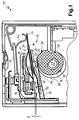
- FIG. 1 is an internal view of a clocking Power control device 11 shown for electric heaters. It has a device switch 12, which to the closes contact. This contact is in individual from a fixed contact bridge 13 attached rounded counter contact 14 and a switching contact 15, which is attached to the device switch 12. Of the Switch contact 15 is a commonly used dome-shaped Contact head attached by riveting.
- the switch contact 15 is one at one end elongated bistable snap spring 16 attached and protrudes both sides over this over.
- the snap spring has two elongated hairpin-shaped legs 22 on which the Switch contact 15 opposite end 17 on a support 18 are attached. Between the legs 22 of the snap spring 16 runs a snap bracket 19 which is close to the switch contact 15 supporting end of the snap spring bent upwards runs in the direction of the free end 17, and there arched curved under tension against one Abutment 20 is created.
- This abutment is on one Support plate 21 attached and is preferably part of the carrier 18 also fastened on the support plate 21 educated.
- the function of the device switch is basically as follows off: is the point at which the snap bracket 19 abuts the abutment 20, above the level of two hairpin-shaped legs 22 of the snap spring 16, so the snap spring 16 is in a first position.
- the switching contact 15 becomes against the counter contact 14 pressed. Will now on the free end 17 of the snap spring 16th Exerted pressure and this according to Fig. 1 down deflected, the point approaches the snap bracket 19 in the abutment 20 of the level of the legs 22.
- the switch contact 15 carrying the end of Snap spring 16 abruptly by the snap bracket 19 is bent away below. In this way the switch contact is located 15 no longer on the counter contact 14 and the contact or the device switch 12 is in a second position open.
- the switching process of the snap spring 16 is triggered by an actuator in the form of a curved bimetallic strip 24.
- This carries on one of the snap springs 16 facing top, which is mostly straight, a heating element 25 or the like. With one end, the hook-shaped is bent, the bimetallic strip 24 is exposed End 17 of the snap spring 16.
- the combination is the two metals that cause the bimetal effect are chosen that the metal with the larger coefficient of expansion the side of the bimetallic strip lying against the heating element 25 24 lies.
- the heating element 25 is only when closed Contact between the switching contact 15 and the counter contact 14 flows through with electricity, as well as parallel connected electrical heating device with power.
- the heating element 25 heats Bimetal strip 24, this changes its shape and presses due to an increasing curvature in the direction of the snap spring 16 on their free end 17.
- the free end 17 of the snap spring 16 is so far pressed down that the leg 22 below the Switchover point is whereupon the snap spring snaps and releases the switching contact 15 from the counter contact 14.
- the power supply to the heating element 25 and interrupted to the electric heater, and by that As cooling begins, the bimetallic strip 24 migrates again back to its original position. If the Switching point, the snap spring 16 snaps back again, the switching contact 15 abuts the counter contact 14 and the The heating process starts again.
- a change in this path length is known achieved that the support plate 21, the snap spring 16th carries, with a projection 27 against the outer radius one Power cam 28, which is on an axis 29th is pressed. This will make the power adjustment device formed while the axis 29 the actuating means forms.
- This metal element 31 is biased so that the support plate 21 against the outer radius of the power cam 28 is present.
- this power cam has 28 a variable radius. Through a Rotation of an operator on the axis 29 depends on set position of the projection 27 at another Instead of on the outer circumference of the power cam 28, and depending on the radius of the disc at this point the support plate 21 and thus the snap spring 16 in one specific position to the counter contact 14 and the bimetallic strip 24th
- the radius is in a position with a low power level the power cam large so that the free end 17 is close to the bimetallic strip 24 and this is already after a short time, switching the snap spring 16 and so a separation of the contacts 14 and 15 can cause.
- the power cam shows a position with high power 28 on a small radius, so that the free end 17th is located at a greater distance from the bimetallic strip 24. As a result, it has to go a long way (corresponds to one longer period) to move the snap spring 16 to Bring to snap.
- the switching contact 15 When the contact is open, the switching contact 15 lies with it on the side facing away from the counter contact 14 at a counter stop 33 at.
- the distance between the switch contact 15 and the counter-stop 33 is designated D and determines how far the snap spring 16 after actuation of its free end 17 snapped.
- D The distance between the switch contact 15 and the counter-stop 33. The larger D is, the lower they are Leg 22 after snapping below the abutment 20th and consequently the bimetallic strip 24 must continue upwards hike to reach the switch point.
- variable contact pitch D achieved in that the counterstop 33 part is a wiper spring 34 which has an angled end is attached to the housing of the power control device 11 and the other free end 35 is slightly hook-shaped is. It lies on the outer radius of a second distance cam 36, which is adjacent to the first cam 28 is located on the axis 29. So the distance adjustment device educated.
- the distance cam 36 also a variable radius.
- the resilient Attachment of the wiper spring 34 to the housing becomes this in every position against the outer radius of the distance cam 36 pressed.
- the counter stop 33 thus changes its position depends on the radius of the distance cam 36.
- the shape of the cams 28 and 36 is as follows described:
- the power cam 28 has one for such applications known course of the outer radius.
- a ZERO position of the power control device 11 is the Radius maximum to continuously decrease up to a place for maximum performance 38 where he has an additional Has indentation inwards.
- This indentation 38 not only increases the middle one due to its reduced radius Power output once again considerably, but gives you one Users the clearly noticeable feedback that the top one Power level is set.
- After the indentation 38 is the section 37 of the ZERO position.
- the course of the distance cam 36 corresponds to Area of section 37 that of the power cam 28.
- the radius then takes up to a second section 39 about from section 37 more than at Power cam 28, from there on again continuously to climb up to a third section, the Indentation 38 corresponds. That means that the radius first decreased and then enlarged.
- the contact distance D is small in the areas in which a high setting accuracy and a safe Function of the device switch is required. These are the lower and the upper performance range. In the medium performance range in which the requirements for setting accuracy but the cracking rate is lower contact distance D is larger.
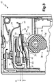
- FIG. 2 shows the power control device 11 from FIG. 1 shown again.
- the setting is Power from a low power in Fig. 1 by Twisting the axis 29 changed to a medium power been.
- the projection 27 and the end of the wiper spring 34 in each section 39 the corresponding cam, the ZERO position section 37 is roughly opposite.
- the end 35 of the Grinder spring 34 a good distance away from the snap spring 16 is located as the projection 27 of the support plate 21.
- the legs 22 of the snap spring 16 a little further above the switchover point on Abutments 20 are as in Fig. 1. This means that the free end 17 of the snap spring 16 further down must be pressed until the snap spring snaps.
- the function is the same as in FIG. 1.
- FIG. 3 shows the power control device 11 with the power setting from Fig. 2, but in a position in the snap spring 16 is snapped and the switch contact 15 has separated from the counter contact 14.
- the switch contact 15 is now with its back on the counter stop 33 at. It can clearly be seen that the legs 22 of the snap spring 16 lie below the abutment 20. Based on this Fig. 3 can be the inventive adjustment of the contact distance through the movable counter contact 33 particularly represent well. Due to the changing radii of the Cam discs 28 and 36 are not only the device switch 12 changed its position to the bimetal strip 24, but also the relative position between the counterstop 33 and the support plate 21 or the point at which the counter-stop 33 is closest to the support plate 21.
- the wiper spring 34 is preferably made of the same resilient Material like the snap spring 16 made.
- the counter attack 33 is made by turning a right angle Section formed in the direction of the switching contact 15. He can through a cutout in the support plate 21st protrude through.
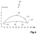
- FIG. 4 is a diagram 40 showing the click rates above the ED shows a dashed click rate curve 41 a power control device according to the prior art shown. It begins with a starting point 46 low click rate of about one click per minute is in its course with increasing ED first in a curve curved at the top and reaches one at its uppermost point 42 Cracking rate of over 4 cracks per minute. From an ED of About 50 percent, curve 41 drops again to one Endpoint 47 with a click rate of approximately one click per Minute.
- the solid click rate curve 44 of the invention Power control device 11 also begins at the starting point 46, but rises less sharply to a top one Point 45, the at less than two pops per minute lies, and falls from there to the end point 47. Man clearly sees the reduction in the cracking rate in the medium performance range.
Landscapes
- Control Of Eletrric Generators (AREA)
- Steering Control In Accordance With Driving Conditions (AREA)
- Cookers (AREA)
- Control Of Stepping Motors (AREA)
- Control Of Resistance Heating (AREA)
- Mechanisms For Operating Contacts (AREA)
- Feedback Control In General (AREA)
- Thermally Actuated Switches (AREA)
- Control Of Position Or Direction (AREA)
- Breakers (AREA)
- Electric Stoves And Ranges (AREA)
- Control Of Electric Motors In General (AREA)
- Push-Button Switches (AREA)
Abstract
Description
- Fig. 1
- eine Innenansicht eines erfindungsgemäßen Leistungssteuergeräts mit einer Verstelleinrichtung, die an den Außenradien zweier Kurvenscheiben anliegen, wobei der Kontakt eines Geräteschalters geschlossen ist, auf einem niedrigen Leistungsniveau;
- Fig. 2
- dieselbe Ansicht wie in Fig. 1, wobei ein mittleres Leistungsniveau eingestellt ist;
- Fig. 3
- die Ansicht aus Fig. 2 mit geöffnetem Schaltkontakt und
- Fig. 4
- die Kurven der Knackraten entsprechend dem Stand der Technik und der vorliegenden Erfindung.
Claims (10)
- Leistungssteuergerät mit einer Verstelleinrichtung für einen darin enthaltenen Geräteschalter (12), insbesondere für Elektro-Wärmegeräte, dessen Positionsänderung eine Änderung eines einstellbaren Leistungsniveaus zur Folge hat und der einen Schaltkontakt (15) trägt, der in einer EIN-Stellung an einem Gegenkontakt (14) anliegt, und insbesondere das Elektro-Wärmegerät mit Leistung versorgt, und in einer AUS-Stellung mit einem veränderbaren Kontaktabstand (D) zum Gegenkontakt an einem Gegenanschlag (33) anliegt, dadurch gekennzeichnet, daß die Verstelleinrichtung eine Leistungs-Verstelleinrichtung für das Leistungsniveau und eine davon gesonderte Kontaktabstands-Verstelleinrichtung sowie Betätigungsmittel (29) zu deren Betätigung aufweist.
- Leistungssteuergerät nach Anspruch 1, dadurch gekennzeichnet, daß sowohl die Leistungs-Verstelleinrichtung als auch die Kontaktabstands-Verstelleinrichtung gleichzeitig mit gemeinsamen Betätigungsmitteln (29) betätigbar sind.
- Leistungssteuergerät nach Anspruch 1 oder 2, dadurch gekennzeichnet, daß die Leistungs-Verstelleinrichtung, insbesondere auch die Kontaktabstands-Verstelleinrichtung, mechanisch ausgebildet ist, vorzugsweise mittels Positionsänderungen infolge einer mechanischen Beaufschlagung.
- Leistungssteuergerät nach einem der vorhergehenden Ansprüche, dadurch gekennzeichnet, daß die Leistungs-Verstelleinrichtung zur Positionsänderung des Geräteschalters (12) eine Leistungs-Kurvenscheibe (28) mit variierendem Radius aufweist, an deren Außenradius der Geräteschalter durch eine Vorspannung elastisch angedrückt anliegt.
- Leistungssteuergerät nach einem der vorhergehenden Ansprüche, dadurch gekennzeichnet, daß die Kontaktabstands-Verstelleinrichtung eine Abstands-Kurvenscheibe (36) mit variierendem Radius aufweist, an deren Außenradius eine den Gegenanschlag (33) tragende und/oder zumindest teilweise bildende Vorrichtung, insbesondere eine Zusatzfeder (34), durch eine Vorspannung elastisch angedrückt anliegt.
- Leistungssteuergerät nach Anspruch 4 oder 5, dadurch gekennzeichnet, daß beide Kurvenscheiben (28,36) auf einer Achse (29) angebracht sind, die mit einem Betätigungsglied von einem Benutzer drehbar ist.
- Leistungssteuergerät nach einem der Ansprüche 4 bis 6, dadurch gekennzeichnet, daß der Außenradius der Leistungs-Kurvenscheibe (28) bei einer NULL-Stellung (37) des Leistungssteuergeräts maximal ist, und sich von diesem Abschnitt an in einer Umfangsrichtung, die entgegengesetzt zu einer bevorzugten Betätigungsrichtung des Leistungssteuergeräts ist, stetig bis an den Abschnitt der NULL-Stellung verringert.
- Leistungssteuergerät nach einem der Ansprüche 5 bis 7, dadurch gekennzeichnet, daß der Außenradius der Abstands-Kurvenscheibe (36) bei der NULL-Stellung (37) des Leistungssteuergerätes maximal ist, sich von diesem Abschnitt an in der zur bevorzugten Betätigungsrichtung entgegengesetzten Richtung bis zu einem zweiten Abschnitt (39), der dem ersten Abschnitt in etwa gegenüberliegt und einen minimalen Außenradius aufweist, verringert und sich von hier an in einem dritten Abschnitt wieder bis an den Abschnitt der NULL-Stellung vergrößert.
- Leistungssteuergerät nach einem der vorhergehenden Ansprüche, dadurch gekennzeichnet, daß der Geräteschalter (12) als Schnappschalter, insbesondere mit einer zweiteiligen bistabilen Schnappfeder (16), ausgeführt ist, der den Schaltkontakt (15) gegen mindestens eine Schaltstellung belastet.
- Leistungssteuergerät nach Anspruch 9, dadurch gekennzeichnet, daß die Schnappfeder (16) zur Verbesserung der Schaltvorgänge der Kontakte (14,15) eine Schlaggabel aufweist.
Applications Claiming Priority (2)
| Application Number | Priority Date | Filing Date | Title |
|---|---|---|---|
| DE19736308A DE19736308A1 (de) | 1997-08-21 | 1997-08-21 | Leistungssteuergerät |
| DE19736308 | 1997-08-21 |
Publications (3)
| Publication Number | Publication Date |
|---|---|
| EP0898291A2 true EP0898291A2 (de) | 1999-02-24 |
| EP0898291A3 EP0898291A3 (de) | 1999-06-23 |
| EP0898291B1 EP0898291B1 (de) | 2004-05-06 |
Family
ID=7839662
Family Applications (1)
| Application Number | Title | Priority Date | Filing Date |
|---|---|---|---|
| EP98114913A Expired - Lifetime EP0898291B1 (de) | 1997-08-21 | 1998-08-08 | Leistungssteuergerät |
Country Status (9)
| Country | Link |
|---|---|
| US (1) | US6064045A (de) |
| EP (1) | EP0898291B1 (de) |
| AT (1) | ATE266252T1 (de) |
| AU (1) | AU727574B2 (de) |
| DE (2) | DE19736308A1 (de) |
| ES (1) | ES2219816T3 (de) |
| PL (1) | PL187381B1 (de) |
| TR (1) | TR199801628A3 (de) |
| ZA (1) | ZA987520B (de) |
Cited By (4)
| Publication number | Priority date | Publication date | Assignee | Title |
|---|---|---|---|---|
| WO2004090923A1 (de) * | 2003-04-11 | 2004-10-21 | E.G.O. Elektro-Gerätebau GmbH | Energiesteuergerät |
| WO2006015710A1 (de) * | 2004-08-03 | 2006-02-16 | E.G.O. Elektro-Gerätebau GmbH | Vorrichtung zum schalten von mehreren heizeinrichtungen eines kochgeräts sowie kochgerät mit einer solchen vorrichtung |
| US7345572B2 (en) | 2004-02-24 | 2008-03-18 | Electrovac, Fabrikation Elektrotechnischer Spezialartikel Ges.M.B.H. | Temperature sensor |
| EP1724799A3 (de) * | 2005-05-18 | 2008-03-19 | E.G.O. ELEKTRO-GERÄTEBAU GmbH | Elektrische Kontaktverbindung und Verfahren zur Herstellung |
Families Citing this family (9)
| Publication number | Priority date | Publication date | Assignee | Title |
|---|---|---|---|---|
| DE102004020977B4 (de) * | 2004-04-22 | 2007-06-21 | E.G.O. Elektro-Gerätebau GmbH | Vorrichtung zur variablen Einstellung der Leistung einer Heizeinrichtung mit mindestens zwei Heizkreisen |
| US7180038B2 (en) * | 2004-08-03 | 2007-02-20 | E.G.O. Elektro-Geraetebau Gmbh | Device for switching on and off several heating mechanisms of cooking equipment as well as cooking equipment with such a device |
| US8884195B2 (en) | 2011-12-09 | 2014-11-11 | E.G.O. Elektro-Gerätebau GmbH | Heating device, method of producing a heating device and method for operating a heating device |
| US8933377B2 (en) | 2011-12-09 | 2015-01-13 | E.G.O. Elektro-Gerätebau GmbH | Control device for an electrical heating device for a cooking field, cooking field and method for operating such an electrical heating device |
| DE102013216290B4 (de) | 2013-08-16 | 2015-09-03 | E.G.O. Elektro-Gerätebau GmbH | Heizeinrichtung und Verfahren zum Betrieb einer Heizeinrichtung |
| US11566793B2 (en) * | 2015-01-20 | 2023-01-31 | Robertshaw Controls Company | Electro-mechanical energy regulator providing enhanced simmer performance |
| KR200488089Y1 (ko) | 2018-08-07 | 2018-12-12 | 주식회사 박전자 | 전기레인지의 온도제어장치 |
| US11810741B2 (en) | 2020-11-09 | 2023-11-07 | Robertshaw Controls Company | Increased push travel alternative for energy regulator |
| DE102023200840A1 (de) * | 2023-02-02 | 2024-08-08 | E.G.O. Elektro-Gerätebau GmbH | Schaltvorrichtung und Verfahren zum Betrieb einer Schaltvorrichtung |
Family Cites Families (11)
| Publication number | Priority date | Publication date | Assignee | Title |
|---|---|---|---|---|
| CH391057A (de) * | 1962-03-21 | 1965-04-30 | Elcalor Ag | Bimetallschalter und Verwendung desselben |
| DE1565682A1 (de) * | 1966-09-17 | 1970-03-26 | Licentia Gmbh | Temperaturabhaengige Schaltvorrichtung fuer elektrisch beheizte Geraete |
| DE1930935A1 (de) * | 1969-06-19 | 1970-12-23 | Siemens Ag | Nockengesteuerte Kontakteinrichtung |
| US3987268A (en) * | 1973-09-28 | 1976-10-19 | Matsushita Electric Industrial Co., Ltd. | Power switching and control mechanism for induction heating apparatus |
| US4206344A (en) * | 1976-06-09 | 1980-06-03 | E.G.O. Regeltechnik Gmbh | Electric power controllers |
| DE2731782C2 (de) * | 1977-07-14 | 1983-04-21 | E.G.O.- Regeltechnik GmbH, 7519 Oberderdingen | Steuergerät für Elektrokochplatten |
| DE2836882C2 (de) * | 1978-08-23 | 1986-08-14 | E.G.O. Elektro-Geräte AG, Zug | Steuergerät für Elektrokochplatten |
| DE3223461C2 (de) * | 1982-06-23 | 1986-09-11 | Bosch-Siemens Hausgeräte GmbH, 7000 Stuttgart | Temperaturregler |
| DE3508248A1 (de) * | 1985-03-08 | 1986-09-11 | E.G.O. Elektro-Geräte Blanc u. Fischer, 7519 Oberderdingen | Elektrische beheizung fuer ein bimetall, insbesondere fuer ein elektrisches leistungssteuergeraet |
| DE3639186A1 (de) * | 1986-11-15 | 1988-05-26 | Ego Elektro Blanc & Fischer | Elektro-schaltgeraet, insbesondere zur leistungssteuerung |
| GB9409489D0 (en) * | 1994-05-12 | 1994-06-29 | Diamond H Controls Ltd | Energy regulator |
-
1997
- 1997-08-21 DE DE19736308A patent/DE19736308A1/de not_active Withdrawn
-
1998
- 1998-08-08 DE DE59811309T patent/DE59811309D1/de not_active Expired - Lifetime
- 1998-08-08 EP EP98114913A patent/EP0898291B1/de not_active Expired - Lifetime
- 1998-08-08 ES ES98114913T patent/ES2219816T3/es not_active Expired - Lifetime
- 1998-08-08 AT AT98114913T patent/ATE266252T1/de not_active IP Right Cessation
- 1998-08-18 PL PL98328046A patent/PL187381B1/pl not_active IP Right Cessation
- 1998-08-20 TR TR1998/01628A patent/TR199801628A3/tr unknown
- 1998-08-20 US US09/137,635 patent/US6064045A/en not_active Expired - Fee Related
- 1998-08-20 ZA ZA987520A patent/ZA987520B/xx unknown
- 1998-08-21 AU AU80883/98A patent/AU727574B2/en not_active Ceased
Cited By (5)
| Publication number | Priority date | Publication date | Assignee | Title |
|---|---|---|---|---|
| WO2004090923A1 (de) * | 2003-04-11 | 2004-10-21 | E.G.O. Elektro-Gerätebau GmbH | Energiesteuergerät |
| CN1774783B (zh) * | 2003-04-11 | 2010-11-10 | E.G.O.电气设备制造股份有限公司 | 能量控制设备 |
| US7345572B2 (en) | 2004-02-24 | 2008-03-18 | Electrovac, Fabrikation Elektrotechnischer Spezialartikel Ges.M.B.H. | Temperature sensor |
| WO2006015710A1 (de) * | 2004-08-03 | 2006-02-16 | E.G.O. Elektro-Gerätebau GmbH | Vorrichtung zum schalten von mehreren heizeinrichtungen eines kochgeräts sowie kochgerät mit einer solchen vorrichtung |
| EP1724799A3 (de) * | 2005-05-18 | 2008-03-19 | E.G.O. ELEKTRO-GERÄTEBAU GmbH | Elektrische Kontaktverbindung und Verfahren zur Herstellung |
Also Published As
| Publication number | Publication date |
|---|---|
| TR199801628A2 (xx) | 1999-03-22 |
| ZA987520B (en) | 1999-02-23 |
| EP0898291A3 (de) | 1999-06-23 |
| ATE266252T1 (de) | 2004-05-15 |
| US6064045A (en) | 2000-05-16 |
| AU8088398A (en) | 1999-03-04 |
| EP0898291B1 (de) | 2004-05-06 |
| DE19736308A1 (de) | 1999-02-25 |
| PL187381B1 (pl) | 2004-06-30 |
| AU727574B2 (en) | 2000-12-14 |
| PL328046A1 (en) | 1999-03-01 |
| TR199801628A3 (tr) | 1999-03-22 |
| ES2219816T3 (es) | 2004-12-01 |
| DE59811309D1 (de) | 2004-06-09 |
Similar Documents
| Publication | Publication Date | Title |
|---|---|---|
| EP0898291B1 (de) | Leistungssteuergerät | |
| EP0268098A2 (de) | Elektro-Schaltgerät, insbesondere zur Leistungssteuerung | |
| DE2625716B2 (de) | Leistungssteuergerät | |
| DE1959591B2 (de) | Bimetall-Temperaturregler | |
| DE3709660C2 (de) | Verschluß für ein Haushaltsgerät | |
| DE3543093C2 (de) | ||
| DE2850389C3 (de) | Temperaturregler für Elektrowärmegeräte, insbesondere für Elektrokochplatten | |
| DE3540620C2 (de) | ||
| DE3337530C2 (de) | ||
| DE2435151A1 (de) | Elektrischer leistungsregler | |
| DE3610968C2 (de) | Blockiervorrichtung für die Tür einer Waschmaschine, insbesondere einer Haushaltswaschmaschine | |
| DE1127435B (de) | Mikro-Schnappschalter | |
| DE2619837B2 (de) | Schnappschalter | |
| DE2724527A1 (de) | Temperaturregler | |
| DE2414884C3 (de) | Thermischer Umschalter | |
| DE2150311A1 (de) | Temperaturabhaengiger elektrischer schalter mit einem bimetallischen steuerorgan | |
| EP1154442B1 (de) | Variabler Widerstand und damit versehener Spannungsteiler, Leiterplatte und zahnärztliches Gerät | |
| DE1141739B (de) | Energieregler fuer ein elektrisches Heizgeraet | |
| EP0562287B1 (de) | Leistungssteuergerät | |
| DE1523459A1 (de) | Anzeige- und Steuereinrichtung | |
| DE947503C (de) | Stufenloser Regelschalter fuer elektrische Waermegeraete | |
| DE2702851B2 (de) | Bimetallgesteuerter Schalter | |
| DE102004020977B4 (de) | Vorrichtung zur variablen Einstellung der Leistung einer Heizeinrichtung mit mindestens zwei Heizkreisen | |
| DE4032942A1 (de) | Einrichtung zur steuerung eines umgebungs-einflusses an geraeten | |
| EP0617446A1 (de) | Steuergerät, insbesondere Leistungs-Steuergerät für Elektro-Wärmegeräte |
Legal Events
| Date | Code | Title | Description |
|---|---|---|---|
| PUAI | Public reference made under article 153(3) epc to a published international application that has entered the european phase |
Free format text: ORIGINAL CODE: 0009012 |
|
| AK | Designated contracting states |
Kind code of ref document: A2 Designated state(s): AT CH DE ES FR GB GR IT LI SE |
|
| AX | Request for extension of the european patent |
Free format text: AL;LT;LV;MK;RO;SI |
|
| PUAL | Search report despatched |
Free format text: ORIGINAL CODE: 0009013 |
|
| AK | Designated contracting states |
Kind code of ref document: A3 Designated state(s): AT BE CH CY DE DK ES FI FR GB GR IE IT LI LU MC NL PT SE |
|
| AX | Request for extension of the european patent |
Free format text: AL;LT;LV;MK;RO;SI |
|
| 17P | Request for examination filed |
Effective date: 19991014 |
|
| AKX | Designation fees paid |
Free format text: AT CH DE ES FR GB GR IT LI SE |
|
| 17Q | First examination report despatched |
Effective date: 20030417 |
|
| GRAP | Despatch of communication of intention to grant a patent |
Free format text: ORIGINAL CODE: EPIDOSNIGR1 |
|
| GRAS | Grant fee paid |
Free format text: ORIGINAL CODE: EPIDOSNIGR3 |
|
| GRAA | (expected) grant |
Free format text: ORIGINAL CODE: 0009210 |
|
| AK | Designated contracting states |
Kind code of ref document: B1 Designated state(s): AT CH DE ES FR GB GR IT LI SE |
|
| REG | Reference to a national code |
Ref country code: GB Ref legal event code: FG4D Free format text: NOT ENGLISH |
|
| REG | Reference to a national code |
Ref country code: CH Ref legal event code: EP |
|
| REF | Corresponds to: |
Ref document number: 59811309 Country of ref document: DE Date of ref document: 20040609 Kind code of ref document: P |
|
| REG | Reference to a national code |
Ref country code: SE Ref legal event code: TRGR |
|
| PG25 | Lapsed in a contracting state [announced via postgrant information from national office to epo] |
Ref country code: GR Free format text: LAPSE BECAUSE OF FAILURE TO SUBMIT A TRANSLATION OF THE DESCRIPTION OR TO PAY THE FEE WITHIN THE PRESCRIBED TIME-LIMIT Effective date: 20040806 |
|
| PG25 | Lapsed in a contracting state [announced via postgrant information from national office to epo] |
Ref country code: AT Free format text: LAPSE BECAUSE OF NON-PAYMENT OF DUE FEES Effective date: 20040808 |
|
| GBT | Gb: translation of ep patent filed (gb section 77(6)(a)/1977) |
Effective date: 20040719 |
|
| PG25 | Lapsed in a contracting state [announced via postgrant information from national office to epo] |
Ref country code: LI Free format text: LAPSE BECAUSE OF NON-PAYMENT OF DUE FEES Effective date: 20040831 Ref country code: CH Free format text: LAPSE BECAUSE OF NON-PAYMENT OF DUE FEES Effective date: 20040831 |
|
| REG | Reference to a national code |
Ref country code: ES Ref legal event code: FG2A Ref document number: 2219816 Country of ref document: ES Kind code of ref document: T3 |
|
| ET | Fr: translation filed | ||
| PLBE | No opposition filed within time limit |
Free format text: ORIGINAL CODE: 0009261 |
|
| STAA | Information on the status of an ep patent application or granted ep patent |
Free format text: STATUS: NO OPPOSITION FILED WITHIN TIME LIMIT |
|
| REG | Reference to a national code |
Ref country code: CH Ref legal event code: PL |
|
| 26N | No opposition filed |
Effective date: 20050208 |
|
| PGFP | Annual fee paid to national office [announced via postgrant information from national office to epo] |
Ref country code: ES Payment date: 20100830 Year of fee payment: 13 |
|
| PGFP | Annual fee paid to national office [announced via postgrant information from national office to epo] |
Ref country code: SE Payment date: 20100823 Year of fee payment: 13 Ref country code: IT Payment date: 20100825 Year of fee payment: 13 Ref country code: FR Payment date: 20100901 Year of fee payment: 13 Ref country code: DE Payment date: 20100810 Year of fee payment: 13 |
|
| PGFP | Annual fee paid to national office [announced via postgrant information from national office to epo] |
Ref country code: GB Payment date: 20100823 Year of fee payment: 13 |
|
| REG | Reference to a national code |
Ref country code: SE Ref legal event code: EUG |
|
| GBPC | Gb: european patent ceased through non-payment of renewal fee |
Effective date: 20110808 |
|
| REG | Reference to a national code |
Ref country code: FR Ref legal event code: ST Effective date: 20120430 |
|
| PG25 | Lapsed in a contracting state [announced via postgrant information from national office to epo] |
Ref country code: IT Free format text: LAPSE BECAUSE OF NON-PAYMENT OF DUE FEES Effective date: 20110808 |
|
| REG | Reference to a national code |
Ref country code: DE Ref legal event code: R119 Ref document number: 59811309 Country of ref document: DE Effective date: 20120301 |
|
| PG25 | Lapsed in a contracting state [announced via postgrant information from national office to epo] |
Ref country code: GB Free format text: LAPSE BECAUSE OF NON-PAYMENT OF DUE FEES Effective date: 20110808 Ref country code: FR Free format text: LAPSE BECAUSE OF NON-PAYMENT OF DUE FEES Effective date: 20110831 |
|
| REG | Reference to a national code |
Ref country code: ES Ref legal event code: FD2A Effective date: 20121207 |
|
| PG25 | Lapsed in a contracting state [announced via postgrant information from national office to epo] |
Ref country code: ES Free format text: LAPSE BECAUSE OF NON-PAYMENT OF DUE FEES Effective date: 20110809 |
|
| PG25 | Lapsed in a contracting state [announced via postgrant information from national office to epo] |
Ref country code: SE Free format text: LAPSE BECAUSE OF NON-PAYMENT OF DUE FEES Effective date: 20110809 |
|
| PG25 | Lapsed in a contracting state [announced via postgrant information from national office to epo] |
Ref country code: DE Free format text: LAPSE BECAUSE OF NON-PAYMENT OF DUE FEES Effective date: 20120301 |