EP0897827A2 - Vorrichtung zum Entfernen von Eis-, Schnee- und Wasseransammlungen auf Planen - Google Patents
Vorrichtung zum Entfernen von Eis-, Schnee- und Wasseransammlungen auf Planen Download PDFInfo
- Publication number
- EP0897827A2 EP0897827A2 EP98114036A EP98114036A EP0897827A2 EP 0897827 A2 EP0897827 A2 EP 0897827A2 EP 98114036 A EP98114036 A EP 98114036A EP 98114036 A EP98114036 A EP 98114036A EP 0897827 A2 EP0897827 A2 EP 0897827A2
- Authority
- EP
- European Patent Office
- Prior art keywords
- tarpaulin
- lifting element
- drive
- frame
- lifting
- Prior art date
- Legal status (The legal status is an assumption and is not a legal conclusion. Google has not performed a legal analysis and makes no representation as to the accuracy of the status listed.)
- Withdrawn
Links
Images


Classifications
-
- B—PERFORMING OPERATIONS; TRANSPORTING
- B60—VEHICLES IN GENERAL
- B60J—WINDOWS, WINDSCREENS, NON-FIXED ROOFS, DOORS, OR SIMILAR DEVICES FOR VEHICLES; REMOVABLE EXTERNAL PROTECTIVE COVERINGS SPECIALLY ADAPTED FOR VEHICLES
- B60J7/00—Non-fixed roofs; Roofs with movable panels, e.g. rotary sunroofs
- B60J7/08—Non-fixed roofs; Roofs with movable panels, e.g. rotary sunroofs of non-sliding type, i.e. movable or removable roofs or panels, e.g. let-down tops or roofs capable of being easily detached or of assuming a collapsed or inoperative position
- B60J7/12—Non-fixed roofs; Roofs with movable panels, e.g. rotary sunroofs of non-sliding type, i.e. movable or removable roofs or panels, e.g. let-down tops or roofs capable of being easily detached or of assuming a collapsed or inoperative position foldable; Tensioning mechanisms therefor, e.g. struts
- B60J7/1226—Soft tops for convertible vehicles
- B60J7/1256—Inflatable soft tops
-
- B—PERFORMING OPERATIONS; TRANSPORTING
- B60—VEHICLES IN GENERAL
- B60J—WINDOWS, WINDSCREENS, NON-FIXED ROOFS, DOORS, OR SIMILAR DEVICES FOR VEHICLES; REMOVABLE EXTERNAL PROTECTIVE COVERINGS SPECIALLY ADAPTED FOR VEHICLES
- B60J7/00—Non-fixed roofs; Roofs with movable panels, e.g. rotary sunroofs
- B60J7/08—Non-fixed roofs; Roofs with movable panels, e.g. rotary sunroofs of non-sliding type, i.e. movable or removable roofs or panels, e.g. let-down tops or roofs capable of being easily detached or of assuming a collapsed or inoperative position
- B60J7/10—Non-fixed roofs; Roofs with movable panels, e.g. rotary sunroofs of non-sliding type, i.e. movable or removable roofs or panels, e.g. let-down tops or roofs capable of being easily detached or of assuming a collapsed or inoperative position readily detachable, e.g. tarpaulins with frames, or fastenings for tarpaulins
- B60J7/102—Readily detachable tarpaulins, e.g. for utility vehicles; Frames therefor
Definitions
- the invention relates to a device for removing ice, snow and Water accumulation on tarpaulins, especially on tarpaulins on vehicles which the respective tarpaulin with its upper part is supported by a scaffold.
- the loading structure of a truck behind the driver's cab or also the one of a truck trailer often has a scaffold of a certain height on which a tarpaulin is provided which surrounds the scaffold on all sides to the relevant Loading area or around the existing load, especially from rain and Protect snow.
- the well-known framework consists mainly of transversely standing hoops and from them, longitudinal and bars and / or slats spaced from each other.
- a disadvantage of this construction is that when there is snow and rainwater while the truck is stationary in the form of pools of water on the upper area of the tarpaulin accumulates between the bars, whereby the water can freeze in winter, these masses often pose a danger to subsequent traffic, if they are not removed before the start of the journey.
- the object of the invention is to provide an introductory device mentioned type with which it is possible to accumulate ice, water and snow on tarpaulins of portable goods transport equipment exposed to the weather easy and quick to remove.
- the device according to the invention With the device according to the invention, it is simple and quick possible accumulations of rainwater, ice and snow that are on the Have accumulated on top of the tarpaulin when the trucks in question whose Trailers, but also containers and freight cars, with the appropriate tarpaulins are covered above to remove from these transport devices if these in appropriate weather conditions, especially overnight, outdoors have stood.
- the lifting element which rests on the underside of the tarpaulin, is extended upwards, the tarpaulin top deforming like a pointed roof, whereby the tarpaulin takes on inclined surfaces inclined downwards on all sides, so that the collections in question slide at the same time sideways. It has been found that in this way complete removal of the relevant quantities takes place because of the temporarily formed inclined surfaces of the tarpaulin top are essentially taut, so that a good drain or or slip effect is achieved.
- An advantageous embodiment of the device according to the invention consists in that the lifting force exerted by the lifting element on the tarpaulin upper part from below a maximum value can be limited. This will prevent the tarpaulin from tearing protected.
- the lifting element runs on it Horizontal installation position and maintains this position even during its adjustment. As a result, the tarpaulin top is raised evenly.
- a cheap and simple way of attaching the device according to the invention is that the lifting element designed as an elongated profile with fasteners can be attached longitudinally to the tarpaulin frame.
- a simple structure of the device is that the lifting element forms the upper part of a frame with its lower part on the frame of the Truck or the like to attach that the upper and lower Part of the frame connected with scissor-like crossbars are and that the drive for the lifting element between the two mentioned Parts of the scaffold is effective.
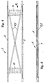
- a truck made of several, horizontal, horizontal top Bow 2, especially in the upper area by several, longitudinal Rods 3 are interconnected.
- Laths 4 are supported the side parts of the bow 2.
- a device On the upper longitudinal center of the scaffold 1 is a device, generally designated 5, for removing ice, snow and Water accumulation on a tarpaulin that surrounds the scaffold 1 on all sides and 1, 2 and 3 is omitted for the sake of clarity, attachable.
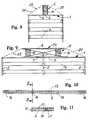
- the device 5 can be seen more precisely. It includes one upper, elongated, plate-like lifting element 6, for example as a U-shaped or can be made of aluminum in a substantially U-shaped profile the same lower element 7, which can be attached to the frame 1, and two lateral handlebar pairs, each consisting of two scissors arranged crosswise Handlebars 8 and 9 exist and connect the two elements 6 and 7 together and at least one drive 10, preferably two drives 10, as shown in FIG. 4 clearly shows to extend the upper lifting element 6 upwards and again to be able to move in.
- the parts 6 to 9 together form a frame of the device 5.
- Each drive 10 is between the upper lifting element 6 and the lower fastener 7 effective.
- the device 5 is in a horizontal position at the top the scaffold 1 attached. Because of the scissor arms 8 and 9 that runs Lifting element 6 in its installed position horizontally and keeps this horizontal position when it is moved up and down.
- each drive via a hose and Control system can be connected to a fluid pressure source.
- fluid pressure source for the or each drive 10 the vehicle's own fluid pressure source are used, for example the air pressure source that is used for the Brake system of a truck (truck) is determined.
- a separate fluid pressure source This is, for example, at Containers or freight cars if the case with a tarpaulin and a support frame are closed and that of ice, snow and water accumulations should be exempt.
- the or each drive 10 can consist of a variable in length, standing between the upper and lower parts 6, 7 of the said frame of the device 5 effective and connected with these parts pressure body.
- a preferred embodiment for such a pressure body consists in one Bellows, as indicated in FIGS. 4 and 6.
- cap 13 in clear form.
- the respective cap 13 is secured by means of pins 16 held in holes 17 of the lifting element 6.
- FIG. 13 shows a hose and control system 18 for the one described above Device 5. It comprises a control device 19 with a control valve 20 and a pressure relief valve 21 and is connected to a hose line 22 with both Fluid pressure source 23 and fluidly connected to the or each drive 10.
- the fluidic control valve 20 has at least two switching positions, wherein whose first switching position the or each or drive 10 with the fluid pressure source 23 connects and, when the control valve is switched, its second switching position the hose system keeps the or each drive depressurized.
- the pressure relief valve 21 ensures that the fluid pressure of the drive 10 supplied Fluid is limited to a predetermined maximum pressure.
- control valve 20 and the pressure relief valve 21 are free passage cross sections of the control valve 20 and the pressure relief valve 21 so dimensioned that the free passage of the pressure relief valve in the open position is greater than the free passage of the one in the first switching position Control valves to ensure the safe function of the pressure relief valve.
- the device explained above can also be used preventively, to avoid from the outset that in particular water accumulations and so that ice can form on the tarpaulin tops of tarpaulin 24.
- the lifting element 6 by means of the drive 10 in the Work position raised and locked in this position. The rain water then runs off immediately and cannot form pools of water. Will the truck or the trailer is used or driven again, the lifting element 6 is previously retracted to its rest position.
Landscapes
- Engineering & Computer Science (AREA)
- Mechanical Engineering (AREA)
- Tents Or Canopies (AREA)
- Buildings Adapted To Withstand Abnormal External Influences (AREA)
Abstract
Description
- Fig. 1
- eine teilweise Seitenansicht auf den Ladenflächengerüstaufbau ohne Abdeckplane für einen Lastkraftwagen,
- Fig. 2
- eine Aufsicht auf die Darstellung nach Fig. 1,
- Fig. 3
- eine Endansicht gemäß dem Pfeil A in Fig. 1,
- Fig. 4
- eine Seitenansicht auf das Ausführungsbeispiel in ausgefahrenem Zustand,
- Fig. 5
- eine Seitenansicht auf das Ausführungsbeispiel in eingefahrenem Zustand,
- Fig. 6
- eine Endansicht gemäß dem Pfeil B in Fig. 4 in größerem Maßstab in ausgefahrenem Zustand des Ausführungsbeispieles,
- Fig. 7
- das Ausführungsbeispiel nach Fig. 6 in eingefahrenem Zustand,
- Fig. 8 und 9
- das Ausführungsbeispiel in End- bzw. Seitenansicht in ausgefahrenem Zustand mit Abdeckplane,
- Fig. 10
- eine Ansicht auf ein Schutzelement des Ausführungsbeispieles,
- Fig. 11
- eine Schnittdarstellung nach der Linie XI-XI in Fig 10,
- Fig. 12
- eine teilweise Schnittdarstellung einer Befestigungsart des Ausführungsbeispieles am oberen Gerüstbereich des Lastkraftwagens,
- Fig. 13
- ein fluidisches Steuerschema zur Betätigung des Ausführungsbeispieles.
Claims (14)
- Vorrichtung (5) zum Entfernen von Eis-, Schnee- und Wasseransammlungen auf Planen (24), insbesondere auf Planen von Fahrzeugen, bei denen die jeweilige Plane mit ihrem Oberteil von einem Gerüst (1) abgestützt gekennzeichnet durch mindestens ein oben am Gerüst (1) unterhalb des Planenoberteiles zu montierendes Hubelement (6), das ausgehend von einer Ruheposition mittels eines Antriebes (10) durch Anheben unter Straffung und spitzdachartiger Verformung (25) des Planenoberteiles in eine Arbeitsposition und durch Absenken wieder in die Ruheposition verstellbar ist.
- Vorrichtung nach Anspruch 1, dadurch Gekennzeichnet, daß die vom Hubelement (6) von unten auf den Planenoberteil (25) ausgeübte Hubkraft auf einen Maximalwert begrenzt bzw. begrenzbar ist.
- Vorrichtung nach einem der Ansprüche 1 und 2, dadurch gekennzeichnet, daß das Hubelement (6) bei Einbaulage horizontal verläuft und in horizontaler Lage verbleibend verstellbar ist.
- Vorrichtung nach einem der Ansprüche 1 bis 3, dadurch gekennzeichnet, daß das als längliches Profil ausgebildete Hubelement (6) mit Befestigungsmitteln (11, 12) längsmittig am Planengerüst (1) befestigbar ist.
- Vorrichtung nach einem der Ansprüche 1 bis 4, dadurch gekennzeichnet, daß das Hubelement (6) den oberen Teil eines Gestelles bildet, das mit einem unteren Teil (7) am Gerüst (1) zu befestigen ist, daß der obere und der untere Teil des Gestelles mit scherenartig über Kreuz angeordneten Lenkern (8, 9) verbunden sind und daß der Antrieb (10) zwischen den beiden erwähnten Teilen (6, 7) des Gerüstes (1) wirksam ist.
- Vorrichtung nach einem der Ansprüche 1 bis 5, dadurch gekennzeichnet, daß der Antrieb (10) fluidisch, insbesondere pneumatisch, betreibbar ist und über ein Schlauch- und Steuersystem (18) an eine Fluiddruckquelle (23) anschließbar ist.
- Vorrichtung nach Anspruch 6, dadurch gekennzeichnet, daß der Antrieb (10) an eine fahrzeugeigene Fluiddruckquelle anschließbar ist.
- Vorrichtung nach einem der Ansprüche 6 und 7, dadurch gekennzeichnet, daß der Antrieb (10) aus mindestens einem durch Einleiten von Fluiddruckmittel in seiner Lange veränderbaren, stehend zwischen dem oberen und unteren Teil des Gestelles (6-9) wirksamen und mit diesen Teilen verbundenen Druckkörper besteht.
- Vorrichtung nach Anspruch 8, dadurch gekennzeichnet, daß der Druckkörper (10) als zylindrischer Faltenbalg ausgebildet ist.
- Vorrichtung nach einem der Ansprüche 6 bis 9, dadurch gekennzeichnet, daß im Schlauch- und Steuersystem (18) ein Steuerventil (20) mit mindestens zwei Schaltstellungen vorgesehen ist, das bei einer ersten Schaltstellung den Antrieb mit der Fluiddruckquelle (23) verbindet und bei einer anderen, zweiten Schaltstellung das Schlauchsystem (22) und den Antrieb drucklos hält.
- Vorrichtung nach einem der Ansprüche 6 bis 10, dadurch gekennzeichnet, daß im Schlauch- und Steuersystem (19) ein Überdruckventil (21) zur Begrenzung des größmöglichen Druckes des dem Antrieb (10) zugeführten Fluids vorgesehen ist.
- Vorrichtung nach den Ansprüchen 10 und 11, dadurch gekennzeichnet, daß der freie Durchlaß des in Offenstellung befindlichen Überdruckventiles (21) größer ist als der freie Durchlaß des in der ersten Stellung befindlichen Steuerventiles (20).
- Vorrichtung nach einem der Ansprüche 1 bis 12, dadurch gekennzeichnet, daß das im wesentlichen als längliches Flachprofil ausgebildete Hubelement (6) an den mit dem Planenoberteil (25) in Berührung gelangenden Längs- und Stirnseiten abgerundet ist.
- Vorrichtung nach einem der Ansprüche 1 bis 12, dadurch gekennzeichnet, daß die Endbereiche des Hubelementes (6) auf seiner dem Planenoberteil (25) zugekehrten Seite mit einer Kappe (13) abgedeckt sind, welche teilweise die Längs- und die Stirnseiten des als längliches Flachprofil ausgebildeten Hubelementes abgerundet übergreift.
Applications Claiming Priority (2)
| Application Number | Priority Date | Filing Date | Title |
|---|---|---|---|
| DE19732348 | 1997-07-28 | ||
| DE1997132348 DE19732348C2 (de) | 1997-07-28 | 1997-07-28 | Vorrichtung zum Entfernen von Eis-, Schnee- und Wasseransammlungen auf Planen |
Publications (2)
| Publication Number | Publication Date |
|---|---|
| EP0897827A2 true EP0897827A2 (de) | 1999-02-24 |
| EP0897827A3 EP0897827A3 (de) | 2000-08-30 |
Family
ID=7837076
Family Applications (1)
| Application Number | Title | Priority Date | Filing Date |
|---|---|---|---|
| EP98114036A Withdrawn EP0897827A3 (de) | 1997-07-28 | 1998-07-28 | Vorrichtung zum Entfernen von Eis-, Schnee- und Wasseransammlungen auf Planen |
Country Status (2)
| Country | Link |
|---|---|
| EP (1) | EP0897827A3 (de) |
| DE (1) | DE19732348C2 (de) |
Cited By (11)
| Publication number | Priority date | Publication date | Assignee | Title |
|---|---|---|---|---|
| EP1106409A3 (de) * | 1999-12-09 | 2002-07-24 | Oy Närko Ab | Abdeckungsrahmen und Trägerelement für Abdeckungsrahmen |
| WO2003101772A3 (de) * | 2002-05-31 | 2005-02-24 | K & M Stahl Behaelter Fassaden | Vorrichtung zur erhöhung der verkehrssicherheit beplanter fahrzeuge |
| WO2005065975A1 (de) * | 2004-01-09 | 2005-07-21 | Bauregger Guenter | Spann-hebeeinrichtung für ein fahrzeugplanenoberteil |
| EP1897769A1 (de) | 2006-09-06 | 2008-03-12 | AMX Automation Technologies GmbH | Vorrichtung zur Entfernung von Regenwasser usw. auf Abdeckplanen von Fahrzeugen |
| DE202010001287U1 (de) | 2010-01-25 | 2010-06-17 | Coatex N.V. | Vorrichtung zur Vermeidung von Schnee- und Eisplattenbildungen bei einem Verdeck aus Planen für ein Transportfahrzeug, wie Lastkraftwagen o.dgl. |
| NL2004044C2 (nl) * | 2009-01-02 | 2010-07-08 | Bootsman Holding Bv | Besturingsysteem aan boord van een vrachtwagen voor het oppompen en laten leeglopen van een pneumatische slang die zich uitstrekt over de lengte van het laadruim dicht onder het dak van het met een dekkleed afgesloten laadruim van de vrachtwagen en werkwijze voor het oppompen en laten leeg lopen van die slang. |
| EP2409869A2 (de) | 2010-07-20 | 2012-01-25 | Sioen Industries NV | Aufblasbarer Balg zum Anheben des flexiblen Daches eines LKW-Laderaumes |
| EP2409868A2 (de) | 2010-07-23 | 2012-01-25 | Bootsman Holding B.V. | Luftrohr für eine Vorrichtung zum Anheben des flexiblen Dachs des LKW-Laderaums mittels Aufblasen eines Balgs |
| EP2857242A1 (de) * | 2013-10-02 | 2015-04-08 | Klipp & Korn GbR | Planenhebevorrichtung |
| CN110843656A (zh) * | 2019-11-26 | 2020-02-28 | 利辛县江淮扬天汽车有限公司 | 一种车载雨篷过水装置 |
| DE202022001991U1 (de) | 2022-01-27 | 2023-01-20 | Gunter Tannhäuser | Doppelplane als aufblasbare Luftkammer zum Absprengen von Schnee und Vereisungen auf LKWs und -Anhängern |
Families Citing this family (2)
| Publication number | Priority date | Publication date | Assignee | Title |
|---|---|---|---|---|
| AT5685U3 (de) | 2002-07-30 | 2003-04-25 | Guenter Bauregger | Spann-hebevorrichtung für ein fahrzeugplanenoberteil |
| DE202023102297U1 (de) | 2023-04-27 | 2023-06-14 | Günter Bauregger | Vorrichtung zur Beseitigung von gefährlichen Dachlasten vom Aufbau eines Nutzfahrzeugs oder vom Aufbau eines Anhängers eines Nutzfahrzeugs |
Family Cites Families (3)
| Publication number | Priority date | Publication date | Assignee | Title |
|---|---|---|---|---|
| AT408336B (de) * | 1989-05-26 | 2001-10-25 | Pirker Christa | Tragflügelreinigungseinrichtung zum entfernen von mücken od.dgl. von der flügelnase im flug |
| SE502642C2 (sv) * | 1994-02-19 | 1995-11-27 | Thorkild Baumbach | Avisningsanordning för motorfordon med övertäckt lastutrymme |
| DE29706283U1 (de) * | 1997-04-09 | 1997-10-16 | Car-Trac Gerätebau GmbH, 28329 Bremen | Enteisungsanlage für Kfz mit Aufbauten aller Art (Container, Koffer, Planen) |
-
1997
- 1997-07-28 DE DE1997132348 patent/DE19732348C2/de not_active Expired - Fee Related
-
1998
- 1998-07-28 EP EP98114036A patent/EP0897827A3/de not_active Withdrawn
Cited By (12)
| Publication number | Priority date | Publication date | Assignee | Title |
|---|---|---|---|---|
| EP1106409A3 (de) * | 1999-12-09 | 2002-07-24 | Oy Närko Ab | Abdeckungsrahmen und Trägerelement für Abdeckungsrahmen |
| WO2003101772A3 (de) * | 2002-05-31 | 2005-02-24 | K & M Stahl Behaelter Fassaden | Vorrichtung zur erhöhung der verkehrssicherheit beplanter fahrzeuge |
| WO2005065975A1 (de) * | 2004-01-09 | 2005-07-21 | Bauregger Guenter | Spann-hebeeinrichtung für ein fahrzeugplanenoberteil |
| EP1897769A1 (de) | 2006-09-06 | 2008-03-12 | AMX Automation Technologies GmbH | Vorrichtung zur Entfernung von Regenwasser usw. auf Abdeckplanen von Fahrzeugen |
| AT504083B1 (de) * | 2006-09-06 | 2008-11-15 | Amx Automation Technologies Gmbh | Vorrichtung zur sicheren entfernung von regenwasser, schnee oder eis auf abdeckplanen |
| NL2004044C2 (nl) * | 2009-01-02 | 2010-07-08 | Bootsman Holding Bv | Besturingsysteem aan boord van een vrachtwagen voor het oppompen en laten leeglopen van een pneumatische slang die zich uitstrekt over de lengte van het laadruim dicht onder het dak van het met een dekkleed afgesloten laadruim van de vrachtwagen en werkwijze voor het oppompen en laten leeg lopen van die slang. |
| DE202010001287U1 (de) | 2010-01-25 | 2010-06-17 | Coatex N.V. | Vorrichtung zur Vermeidung von Schnee- und Eisplattenbildungen bei einem Verdeck aus Planen für ein Transportfahrzeug, wie Lastkraftwagen o.dgl. |
| EP2409869A2 (de) | 2010-07-20 | 2012-01-25 | Sioen Industries NV | Aufblasbarer Balg zum Anheben des flexiblen Daches eines LKW-Laderaumes |
| EP2409868A2 (de) | 2010-07-23 | 2012-01-25 | Bootsman Holding B.V. | Luftrohr für eine Vorrichtung zum Anheben des flexiblen Dachs des LKW-Laderaums mittels Aufblasen eines Balgs |
| EP2857242A1 (de) * | 2013-10-02 | 2015-04-08 | Klipp & Korn GbR | Planenhebevorrichtung |
| CN110843656A (zh) * | 2019-11-26 | 2020-02-28 | 利辛县江淮扬天汽车有限公司 | 一种车载雨篷过水装置 |
| DE202022001991U1 (de) | 2022-01-27 | 2023-01-20 | Gunter Tannhäuser | Doppelplane als aufblasbare Luftkammer zum Absprengen von Schnee und Vereisungen auf LKWs und -Anhängern |
Also Published As
| Publication number | Publication date |
|---|---|
| DE19732348C2 (de) | 1999-07-08 |
| DE19732348A1 (de) | 1999-02-25 |
| EP0897827A3 (de) | 2000-08-30 |
Similar Documents
| Publication | Publication Date | Title |
|---|---|---|
| DE19732348C2 (de) | Vorrichtung zum Entfernen von Eis-, Schnee- und Wasseransammlungen auf Planen | |
| DE1755619B2 (de) | Kraftfahrzeug mit einem abnehmbaren Dachaufsatz | |
| DE68905328T2 (de) | Dachöffnungseinrichtung für ein Industriefahrzeug mit einer Wagenplane. | |
| EP2091852B1 (de) | Dachentwässerung für lastkraftwagen | |
| DE10252682A1 (de) | Fahrzeug mit Ladeboxen oder Ladeflächen | |
| EP1897769B1 (de) | Vorrichtung zur Entfernung von Regenwasser usw. auf Abdeckplanen von Fahrzeugen | |
| EP1289792A2 (de) | Stromabnehmer für elektrisch betriebene schienenfahrzeuge | |
| DE3932944A1 (de) | Vorrichtung zum anbau eines schneepfluges an ein fahrzeug | |
| DE1680290B1 (de) | Stossstange fuer Kraftfahrzeuge | |
| DE2260224C2 (de) | Fahrzeug zum Transport von Behältern u.dgl | |
| DE29723275U1 (de) | Vorrichtung zum Entfernen von Eis-, Schnee- und Wasseransammlungen auf Planen | |
| EP3428086A1 (de) | Aufbewahrungs- und/oder transportsystem für transportable zaunelemente | |
| DE102016013526B4 (de) | Fahrzeugaufbau für Nutzfahrzeuge | |
| EP0882612B1 (de) | Zusammenschiebbares Verdeck für Fahrzeugaufbauten u.Container | |
| DE102018104706A1 (de) | Auffahrschiene | |
| DE102008021726B4 (de) | Ladebordwand | |
| EP2857242B1 (de) | Planenhebevorrichtung | |
| DE20220225U1 (de) | Fahrzeug mit Ladeboxen oder Ladeflächen | |
| DE19959673C2 (de) | Fahrzeuganhänger | |
| DE202022001629U1 (de) | Faltbarer Auslegerarm zum Ausbringen von Flüssigdünger | |
| DE3027117A1 (de) | Aus einer zugmaschine und einem sattelanhaenger bestehender sattelzug | |
| DE1658611C (de) | Vorrichtung zum Überbrücken von Deh nungsfugen in Brücken, Straßen, Start und Rollbahnen od dgl | |
| EP2383133B1 (de) | Vorrichtung zum bereichsweisen Anheben einer Dachplane | |
| EP2049352B1 (de) | Stützeinrichtung für ein fahrzeugplanenoberteil | |
| DE685228C (de) | Lastwagen mit seitlich kippbarer Bruecke |
Legal Events
| Date | Code | Title | Description |
|---|---|---|---|
| PUAI | Public reference made under article 153(3) epc to a published international application that has entered the european phase |
Free format text: ORIGINAL CODE: 0009012 |
|
| AK | Designated contracting states |
Kind code of ref document: A2 Designated state(s): AT BE CH CY DE DK ES FI FR GB GR IE IT LI LU MC NL PT SE |
|
| AX | Request for extension of the european patent |
Free format text: AL;LT;LV;MK;RO;SI |
|
| PUAL | Search report despatched |
Free format text: ORIGINAL CODE: 0009013 |
|
| AK | Designated contracting states |
Kind code of ref document: A3 Designated state(s): AT BE CH CY DE DK ES FI FR GB GR IE IT LI LU MC NL PT SE |
|
| AX | Request for extension of the european patent |
Free format text: AL;LT;LV;MK;RO;SI |
|
| AKX | Designation fees paid | ||
| STAA | Information on the status of an ep patent application or granted ep patent |
Free format text: STATUS: THE APPLICATION IS DEEMED TO BE WITHDRAWN |
|
| 18D | Application deemed to be withdrawn |
Effective date: 20010301 |
|
| REG | Reference to a national code |
Ref country code: DE Ref legal event code: 8566 |