EP0897331B1 - Doppelplattenkörper - Google Patents
Doppelplattenkörper Download PDFInfo
- Publication number
- EP0897331B1 EP0897331B1 EP97915416A EP97915416A EP0897331B1 EP 0897331 B1 EP0897331 B1 EP 0897331B1 EP 97915416 A EP97915416 A EP 97915416A EP 97915416 A EP97915416 A EP 97915416A EP 0897331 B1 EP0897331 B1 EP 0897331B1
- Authority
- EP
- European Patent Office
- Prior art keywords
- tubes
- double
- walled body
- body according
- pipes
- Prior art date
- Legal status (The legal status is an assumption and is not a legal conclusion. Google has not performed a legal analysis and makes no representation as to the accuracy of the status listed.)
- Expired - Lifetime
Links
- 125000006850 spacer group Chemical group 0.000 claims abstract description 5
- 238000005520 cutting process Methods 0.000 claims description 8
- 239000000463 material Substances 0.000 claims description 7
- 239000004033 plastic Substances 0.000 claims description 6
- 229920003023 plastic Polymers 0.000 claims description 6
- 238000005304 joining Methods 0.000 claims description 4
- 238000000034 method Methods 0.000 claims description 4
- 238000003754 machining Methods 0.000 claims description 3
- 238000003698 laser cutting Methods 0.000 claims description 2
- 238000010276 construction Methods 0.000 description 7
- 238000004519 manufacturing process Methods 0.000 description 7
- 238000005452 bending Methods 0.000 description 6
- 238000003466 welding Methods 0.000 description 3
- 239000000853 adhesive Substances 0.000 description 2
- 230000001070 adhesive effect Effects 0.000 description 2
- 239000002184 metal Substances 0.000 description 2
- 238000000926 separation method Methods 0.000 description 2
- 230000002411 adverse Effects 0.000 description 1
- 230000000712 assembly Effects 0.000 description 1
- 238000000429 assembly Methods 0.000 description 1
- 229930194909 coatline Natural products 0.000 description 1
- 238000011109 contamination Methods 0.000 description 1
- 230000008878 coupling Effects 0.000 description 1
- 238000010168 coupling process Methods 0.000 description 1
- 238000005859 coupling reaction Methods 0.000 description 1
- 238000013016 damping Methods 0.000 description 1
- 238000005265 energy consumption Methods 0.000 description 1
- 239000006260 foam Substances 0.000 description 1
- 238000005259 measurement Methods 0.000 description 1
- 239000000155 melt Substances 0.000 description 1
- 239000002984 plastic foam Substances 0.000 description 1
- 229910000679 solder Inorganic materials 0.000 description 1
Images


Classifications
-
- B—PERFORMING OPERATIONS; TRANSPORTING
- B32—LAYERED PRODUCTS
- B32B—LAYERED PRODUCTS, i.e. PRODUCTS BUILT-UP OF STRATA OF FLAT OR NON-FLAT, e.g. CELLULAR OR HONEYCOMB, FORM
- B32B3/00—Layered products comprising a layer with external or internal discontinuities or unevennesses, or a layer of non-planar shape; Layered products comprising a layer having particular features of form
- B32B3/10—Layered products comprising a layer with external or internal discontinuities or unevennesses, or a layer of non-planar shape; Layered products comprising a layer having particular features of form characterised by a discontinuous layer, i.e. formed of separate pieces of material
- B32B3/18—Layered products comprising a layer with external or internal discontinuities or unevennesses, or a layer of non-planar shape; Layered products comprising a layer having particular features of form characterised by a discontinuous layer, i.e. formed of separate pieces of material characterised by an internal layer formed of separate pieces of material which are juxtaposed side-by-side
- B32B3/20—Layered products comprising a layer with external or internal discontinuities or unevennesses, or a layer of non-planar shape; Layered products comprising a layer having particular features of form characterised by a discontinuous layer, i.e. formed of separate pieces of material characterised by an internal layer formed of separate pieces of material which are juxtaposed side-by-side of hollow pieces, e.g. tubes; of pieces with channels or cavities
-
- B—PERFORMING OPERATIONS; TRANSPORTING
- B32—LAYERED PRODUCTS
- B32B—LAYERED PRODUCTS, i.e. PRODUCTS BUILT-UP OF STRATA OF FLAT OR NON-FLAT, e.g. CELLULAR OR HONEYCOMB, FORM
- B32B15/00—Layered products comprising a layer of metal
- B32B15/04—Layered products comprising a layer of metal comprising metal as the main or only constituent of a layer, which is next to another layer of the same or of a different material
-
- E—FIXED CONSTRUCTIONS
- E04—BUILDING
- E04C—STRUCTURAL ELEMENTS; BUILDING MATERIALS
- E04C2/00—Building elements of relatively thin form for the construction of parts of buildings, e.g. sheet materials, slabs, or panels
- E04C2/30—Building elements of relatively thin form for the construction of parts of buildings, e.g. sheet materials, slabs, or panels characterised by the shape or structure
- E04C2/34—Building elements of relatively thin form for the construction of parts of buildings, e.g. sheet materials, slabs, or panels characterised by the shape or structure composed of two or more spaced sheet-like parts
- E04C2/36—Building elements of relatively thin form for the construction of parts of buildings, e.g. sheet materials, slabs, or panels characterised by the shape or structure composed of two or more spaced sheet-like parts spaced apart by transversely-placed strip material, e.g. honeycomb panels
-
- B—PERFORMING OPERATIONS; TRANSPORTING
- B32—LAYERED PRODUCTS
- B32B—LAYERED PRODUCTS, i.e. PRODUCTS BUILT-UP OF STRATA OF FLAT OR NON-FLAT, e.g. CELLULAR OR HONEYCOMB, FORM
- B32B2250/00—Layers arrangement
- B32B2250/40—Symmetrical or sandwich layers, e.g. ABA, ABCBA, ABCCBA
-
- B—PERFORMING OPERATIONS; TRANSPORTING
- B32—LAYERED PRODUCTS
- B32B—LAYERED PRODUCTS, i.e. PRODUCTS BUILT-UP OF STRATA OF FLAT OR NON-FLAT, e.g. CELLULAR OR HONEYCOMB, FORM
- B32B2607/00—Walls, panels
-
- Y—GENERAL TAGGING OF NEW TECHNOLOGICAL DEVELOPMENTS; GENERAL TAGGING OF CROSS-SECTIONAL TECHNOLOGIES SPANNING OVER SEVERAL SECTIONS OF THE IPC; TECHNICAL SUBJECTS COVERED BY FORMER USPC CROSS-REFERENCE ART COLLECTIONS [XRACs] AND DIGESTS
- Y10—TECHNICAL SUBJECTS COVERED BY FORMER USPC
- Y10T—TECHNICAL SUBJECTS COVERED BY FORMER US CLASSIFICATION
- Y10T428/00—Stock material or miscellaneous articles
- Y10T428/13—Hollow or container type article [e.g., tube, vase, etc.]
- Y10T428/1352—Polymer or resin containing [i.e., natural or synthetic]
- Y10T428/139—Open-ended, self-supporting conduit, cylinder, or tube-type article
-
- Y—GENERAL TAGGING OF NEW TECHNOLOGICAL DEVELOPMENTS; GENERAL TAGGING OF CROSS-SECTIONAL TECHNOLOGIES SPANNING OVER SEVERAL SECTIONS OF THE IPC; TECHNICAL SUBJECTS COVERED BY FORMER USPC CROSS-REFERENCE ART COLLECTIONS [XRACs] AND DIGESTS
- Y10—TECHNICAL SUBJECTS COVERED BY FORMER USPC
- Y10T—TECHNICAL SUBJECTS COVERED BY FORMER US CLASSIFICATION
- Y10T428/00—Stock material or miscellaneous articles
- Y10T428/24—Structurally defined web or sheet [e.g., overall dimension, etc.]
- Y10T428/24149—Honeycomb-like
- Y10T428/24157—Filled honeycomb cells [e.g., solid substance in cavities, etc.]
-
- Y—GENERAL TAGGING OF NEW TECHNOLOGICAL DEVELOPMENTS; GENERAL TAGGING OF CROSS-SECTIONAL TECHNOLOGIES SPANNING OVER SEVERAL SECTIONS OF THE IPC; TECHNICAL SUBJECTS COVERED BY FORMER USPC CROSS-REFERENCE ART COLLECTIONS [XRACs] AND DIGESTS
- Y10—TECHNICAL SUBJECTS COVERED BY FORMER USPC
- Y10T—TECHNICAL SUBJECTS COVERED BY FORMER US CLASSIFICATION
- Y10T428/00—Stock material or miscellaneous articles
- Y10T428/24—Structurally defined web or sheet [e.g., overall dimension, etc.]
- Y10T428/24273—Structurally defined web or sheet [e.g., overall dimension, etc.] including aperture
- Y10T428/24322—Composite web or sheet
- Y10T428/24331—Composite web or sheet including nonapertured component
Definitions
- the invention relates to a double plate body with cover plates, between which a number of pipes are arranged.
- Double plate body of the type mentioned here can be used wherever constructions with low mass and high rigidity are required, for example fast moving Machine tables.
- Previous lightweight designs were manufactured in sandwich construction, whose Stiffness does not always meet the requirements enough.
- Furthermore, are very machining-intensive Integral designs with elaborate cast or Welded structures known, their manufacture is complex and costly.
- CH 5 06 017 produces a double panel body that has cover plates between them arranged a number of equal length plastic tubes are. These are contiguous along theirs Coat lines glued together and on their Ends closed by the cover plates. adversely are the only low stiffness properties and the complex production of the double-plate body.
- a double plate body proposed that mentioned in claim 1 Features. He is characterized by it from the fact that the tubes have different lengths, first tubes serving as spacers, whose cylinder axes are orthogonal to the cover plate surfaces run, have a length that corresponds to the clear width between the cover plates, that the length of second pipes is chosen is that they each have their end areas engage in openings in the cover plates or these reach through, and that the inside of at least some of the second pipes fasteners, in particular Take up threaded bushings.
- the task The first pipe is made during assembly the distance between the double plate body to fix the cover plates. This will turn on realized in a simple way that the cover plate surfaces exactly parallel at a desired distance are aligned with each other.
- the second pipes have a greater length than the first tubes, due to which their front end areas in the openings of the cover plates at least reach in, preferably reach through them so that created a connection between the cover plates is.
- the assembly of the cover plates and the tube is therefore without further aids, for example Spacers and clamping elements, simple and quickly feasible.
- An embodiment of the double plate body is preferred, where the pipes with their outer surfaces support each other.
- the pipes are arranged between the cover plates so that each Pipe adjacent to at least one other pipe is. It can be provided that the arrangement of the Pipes to each other is such that their lateral surfaces touch, which means that the bending and torsional rigidity of the double plate body is additionally increased.
- An embodiment of the double plate body is particularly preferred, which is characterized in that the end regions of the tubes are connected to the corresponding cover plate. This ensures high rigidity of the entire plate and tube construction.
- the connection is made by means of a cohesive joining process, whereby welded connections are preferred due to their high bending and torsional rigidity and the optimal flow of force. If the double-plate body is subject to a relatively low load, then soldered and / or adhesive connections are also possible.
- Laser welding is proposed as the welding method, since lasers only have a small effective range due to their concentrated heat intensity, which results in low-distortion and low-stress joining.
- NC N umerical C ontrol
- CAD CAD / CAM
- an embodiment of the double-plate body is preferred in which the tubes are cut from rod material by a separation process, in particular laser cutting, and are used without further processing to produce the double-plate body. Due to the clean and exact, that is, flat cutting surface of the tubes separated by a laser, further processing, for example deburring, is not necessary, so that the tubes can be assembled directly. It is also possible to use NC ( N umerical C ontrol) -controlled cutting machines here to reduce costs.
- NC N umerical C ontrol
- cutting process is also to be understood to mean cutting process techniques, for example incorporating or parting off the bar material by means of a suitable plunge turning tool in a lathe.
- An embodiment of the double plate body is also preferred, which is characterized by that the tubes have flat faces at their ends which are orthogonal to the cylinder axes, especially pipe axes. Thereby it is ensured that the cover plate surfaces sit snugly on the faces of the first pipes and that the distance between the cover plates at any point within a narrow tolerance range is constant.
- Double plate body which is characterized by that the fasteners in the second tubes are held by means of plastic fillings. It is possible, the remaining annular space between the inner surface the pipes and the outer surface of the fasteners with a suitable, hardening Foam or pour out mass. This makes it quick and inexpensive Position fixing of the fasteners on the Double plate body realized.
- An embodiment of the double plate body is also preferred, in which the bore of the second Pipes have a thread and / or as a fit, preferably press fit, is formed in the accordingly trained fasteners screwed or plugged in can.
- the thread as well as the fit can be before Assembly of the double plate body, for example before cutting to length from the bar material become. This eliminates the need for tensioning again the pipes or the double plate body, whereby the manufacturing times are reduced.
- the double plate body preferred, in which the tubes as Polygonal tubes are formed.
- the tubes are formed.
- the tubes under bending and / or torsional stress support each other under load distributed forces acting on the pipes, whereby the surface pressure is reduced.
- the surface pressure is reduced.
- the double plate body described below can generally be used wherever Components with low mass and high Rigidity, in particular bending and torsional rigidity, are required. Such are preferred Constructions as machine tables in high-speed machines Application. Another area of application is in vehicle and aircraft construction because there a lightweight design is sought to reduce energy consumption of the drive units used is low to keep.
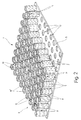
- Figure 1 shows a double plate body 1, with a upper cover plate 3 and a lower cover plate 5. Between the cover plates 3, 5 are pipes 6 arranged with different lengths. So points a first part of the pipes, in the following first pipes 7, a shorter length than a second part of pipes, hereinafter referred to as second pipes 9, on.
- the outer jacket 8 of the tubes 6 is -im Cross-section viewed as a regular polygon and the through bore 10 is circular.
- the so on the circumference of the outer shell 8th serve surfaces extending over the length of the tubes as a system for adjacent pipes. It is possible to change the geometric cross - sectional shape of the To vary outer shell 8 and the bore 10, so that, for example, the bore 10 is rectangular and the outer jacket 8 has a curved shape Has cross section.
- the tubes 6 and the cover plates 3 and 5 made of metal, plastic or the like his. In the following it is assumed that the tubes 6 and the cover plates 3 and 5 from weldable metal.
- FIG. 2 shows parts of the double plate body 1, namely the lower cover plate 5 and a number of first and second pipes.
- openings 13 are introduced, the Contour and size essentially the outside dimension and the contour of the second tubes 9 corresponds.
- the inner diameter of the openings 13 in the cover plates 3, 5 larger than the outer diameter the second pipe 9 is so the end portions 11 of the second tubes 9 into the openings 13 and can reach through them if necessary.
- the openings 13 and 13 preferably have Pipes 6 the same cross-sectional shape respectively Contour on.
- the breakthroughs 13 in can by means of a laser the cover plates 3, 5 cut or by a other separation process, for example stamping, be introduced.
- the second tubes 9 engage their end regions 11 in the openings 13 of the Cover plates 3, 5 a.
- the first tubes 7 lie with its end face 15 on the lower cover plate 5 on.
- the end faces 15 run at right angles the pipe axes so that the cover plate surfaces just lie on the end faces.
- the pipes 6 stand on the bottom, in this embodiment rectangular cover plate 5 so that itself in the connection area between two pipes a gusset 17 forms. Furthermore, the pipes 6 aligned to each other in such a way that they are flat Are in contact with each other. This will make a Uniform flow of force in the connection area ensured between two pipes.
- first tubes 7 By this arrangement and alignment of the pipes is one densely packed cover plate surface realized, whereby each of the first tubes 7 between four second ones Pipes 9 arranged or held by these is so that a parallel to the cover plate surfaces directed relative movement of the first Pipes 7 is not possible.
- the so fixed first tubes 7 have a precisely defined position regarding the surfaces of the two cover plates 3 and 5, whereby a material connection the end faces 15 of the relatively thin-walled first tubes 7 with the cover plates 3, 5 by means of a Lasers, due to its small effective range, is feasible.
- the lower cover plate 5 is on a flat surface placed. Then the second pipes 9 with the end region 11 in the openings 13 of the cover plate 5 inserted. In the remaining gaps the first tubes 7 are arranged. Finally, the top cover plate 3 from above applied to the tubes 7, 9. The kick occurs End region 11 of the second tubes 9 in the openings 13 a. This lowers the top cover plate 3 until its surface on the end faces 15 of the first tubes 7 rests. The pipes 7 and 9 are now with the upper cover plate 3 by means of a laser welded. The weld of the first tubes 7 takes place in that a Cover plate acting laser beam - through this - the end face 15 of the first tubes 7 melts and thus cohesive with the cover plate combines.
- the pipes and the Cover plates by means of a solder or adhesive connection to connect, the type of cohesive Connection preferably depending on the pipe and cover plate materials and / or the requirements the resilience of the double panel body is selectable.
- the lower cover plate 3 in the same way with the pipes 7 and 9 connected.
- fasteners for example Clamping device receptacles, introduced and by means of a hardening mass is held in the bore 10.
- the space between the cover plates 3 and 5 can optionally be foamed with a plastic be, which prevents the ingress of dirt prevents and the rigidity of the Double plate body is increased.
- the fasteners provided for the bore 10 can also be done by means of a detachable connection, for example a thread or a fit, be held in the bore 10.
- the preparatory work in the hole i.e. thread cutting or creating a fit, are possible before installing the double panel body, provided the requirements for the torelance areas are small, that is, they are relatively large could be. Large tolerance ranges because through the thermal joining of the double panel body a distortion of the individual parts (pipes, cover plates) is possible.
- the bore 10 of the second tubes 9 also after the Assembly of the double plate body to accommodate the Fasteners are processed. To this Purpose has the bore 10 of the second tubes 9 Measurement, so even after precision machining the bore 10 has a sufficient wall thickness the tubes 9 is guaranteed.
- Figure 3 shows a plan view of the double plate body 1 with the cover plate removed 3. Same Parts are provided with the same reference numbers, see above that for their description refer to Figures 1 and 2 becomes. It can be seen that the tubes 6 each other touch, which makes them mutually immediate support and thus the rigidity and increase the damping of the double panel body.
- the Wall of the second tubes 9 is thicker than that Wall of the first tubes 7, since the bores 10 Machining allowance for subsequent processing steps exhibit.
- the first Tubes 7 have a larger outer diameter than that second tubes 9.
- the diameter of the tubes 7, 9 and the wall thicknesses are variable and can for example depending on the required strength properties of the double plate body selected or be coordinated.
- Figure 4 shows a sectional view of the double plate body 1 along the drawn in Figure 3 Section line A-A, here the upper cover plate 3 is put on.
- the surfaces of the cover plates 3 and 5 lie completely on the end faces 15 of the first tubes 7 so that the surfaces of the Cover plates 3, 5 run parallel to each other.
- the double-plate body 1 Due to the compact arrangement of the tubes 7, 9 and their homogeneous connection with the cover plates 3, 5, the double-plate body 1 has high bending and torsional rigidity.
- the manufacture of such a double-plate body in lightweight construction is inexpensive to manufacture due to the simple structure and the very easy to create geometries or cutting edges. This is also because all processing steps can be carried out through the use of NC (N umerical C ontrol) machines and thus automation of production is possible.
- NC N umerical C ontrol
Landscapes
- Engineering & Computer Science (AREA)
- Architecture (AREA)
- Civil Engineering (AREA)
- Structural Engineering (AREA)
- Laminated Bodies (AREA)
- Lining Or Joining Of Plastics Or The Like (AREA)
- Heat-Exchange Devices With Radiators And Conduit Assemblies (AREA)
- Rigid Containers With Two Or More Constituent Elements (AREA)
- Packaging Of Annular Or Rod-Shaped Articles, Wearing Apparel, Cassettes, Or The Like (AREA)
- Standing Axle, Rod, Or Tube Structures Coupled By Welding, Adhesion, Or Deposition (AREA)
- Supports For Pipes And Cables (AREA)
- Solid-Sorbent Or Filter-Aiding Compositions (AREA)
- Polishing Bodies And Polishing Tools (AREA)
Applications Claiming Priority (3)
| Application Number | Priority Date | Filing Date | Title |
|---|---|---|---|
| DE19615505A DE19615505C2 (de) | 1996-04-19 | 1996-04-19 | Doppelplattenkörper |
| DE19615505 | 1996-04-19 | ||
| PCT/EP1997/001467 WO1997039887A1 (de) | 1996-04-19 | 1997-03-22 | Doppelplattenkörper |
Publications (2)
| Publication Number | Publication Date |
|---|---|
| EP0897331A1 EP0897331A1 (de) | 1999-02-24 |
| EP0897331B1 true EP0897331B1 (de) | 2002-02-06 |
Family
ID=7791755
Family Applications (1)
| Application Number | Title | Priority Date | Filing Date |
|---|---|---|---|
| EP97915416A Expired - Lifetime EP0897331B1 (de) | 1996-04-19 | 1997-03-22 | Doppelplattenkörper |
Country Status (8)
| Country | Link |
|---|---|
| US (1) | US6187401B1 (da) |
| EP (1) | EP0897331B1 (da) |
| JP (1) | JP2000511831A (da) |
| AT (1) | ATE212906T1 (da) |
| AU (1) | AU2290697A (da) |
| DE (2) | DE19615505C2 (da) |
| DK (1) | DK0897331T3 (da) |
| WO (1) | WO1997039887A1 (da) |
Cited By (1)
| Publication number | Priority date | Publication date | Assignee | Title |
|---|---|---|---|---|
| WO2015062617A1 (de) | 2013-11-04 | 2015-05-07 | Wolfgang Rixen | Verbundplatte |
Families Citing this family (23)
| Publication number | Priority date | Publication date | Assignee | Title |
|---|---|---|---|---|
| DE19734133C2 (de) * | 1997-08-07 | 2002-05-08 | Blueco System 3 R Gmbh | Doppelplattenkörper |
| DE19900934C2 (de) | 1999-01-13 | 2001-06-28 | Mathias Hoffmann | Mehrlagiges Bauelement |
| US7371451B2 (en) * | 2002-08-06 | 2008-05-13 | The Boeing Company | Sandwich type construction structural panel having foam tube core |
| US7432414B2 (en) * | 2003-05-30 | 2008-10-07 | Merck & Co., Inc. | Transgenic mouse having an amyloid precursor protein with a modified beta secretase cleavage site |
| US20050023940A1 (en) * | 2003-07-28 | 2005-02-03 | Van Beusekom Thomas J. | Sound minimizing apparatus |
| US6817586B1 (en) * | 2003-08-08 | 2004-11-16 | Ching-Chiang Lin | Paper pallet |
| US8609226B2 (en) | 2004-03-08 | 2013-12-17 | Herron Intellectual Property Holdings, Llc | High strength low density multi-purpose panel |
| US7021017B2 (en) * | 2004-03-08 | 2006-04-04 | Herron Intellectual Property Holdings, Llc | High strength low density multi-purpose panel |
| DE602005005297T2 (de) * | 2005-04-01 | 2009-03-19 | Sidel Participations | Versteifter Tisch für eine Behälterbehandlungsmachine |
| DE102006005264B4 (de) | 2006-02-02 | 2018-03-08 | Hans Obrecht | Bauelement |
| DE102006056568A1 (de) * | 2006-11-30 | 2008-06-05 | Airbus Deutschland Gmbh | Kernstruktur und Verfahren zur Herstellung einer Kernstruktur |
| US8464490B2 (en) * | 2007-05-09 | 2013-06-18 | Antonio Rapaz | Construction panel |
| US20080276557A1 (en) * | 2007-05-09 | 2008-11-13 | Antonio Rapaz | Construction panel |
| US9010060B2 (en) | 2007-05-09 | 2015-04-21 | Antonio Rapaz | Construction panel |
| DE102008007516A1 (de) | 2008-02-05 | 2009-08-06 | Genima Innovations Marketing Gmbh | Kernstruktur für den Aufbau mehrlagiger Platten oder Schalen |
| US8597455B1 (en) | 2009-10-02 | 2013-12-03 | Metacomb, Inc. | Translucent building material comprising corrugated cardboard |
| US20110204611A1 (en) * | 2010-02-18 | 2011-08-25 | Daimler Trucks North America Llc | Fiber reinforced polymer frame rail |
| EP2657932A4 (en) * | 2010-12-21 | 2017-01-11 | Yoshiharu Kitamura | Soundproofing plate which does not obstruct airflow |
| US8714304B2 (en) * | 2012-09-21 | 2014-05-06 | Yoshiharu Kitamura | Soundproofing plate and soundproofing device permitting air flow |
| DE202016102094U1 (de) * | 2016-04-21 | 2016-05-06 | Horst Witte Gerätebau Barskamp KG | Sandwichplatte |
| EP3351702A4 (en) * | 2016-10-31 | 2019-04-10 | Yue Zhang | METAL PLATE WITH SANDWICH SPECIFIED HOLLOWS AND THEIR USE |
| KR102074389B1 (ko) * | 2017-12-28 | 2020-02-06 | 한국세라믹기술원 | 계층적 적층 튜브 구조 |
| AU2019389149A1 (en) * | 2018-11-28 | 2021-06-17 | President And Fellows Of Harvard College | Structural design principles for diagonal bracings in truss and beam support systems |
Family Cites Families (18)
| Publication number | Priority date | Publication date | Assignee | Title |
|---|---|---|---|---|
| BE630464A (da) | ||||
| US2837788A (en) | 1955-07-18 | 1958-06-10 | Dante V Mazzocco | Panel core constructions |
| US3579411A (en) * | 1967-09-27 | 1971-05-18 | William L Mackie | Filament reinforced structure and method of making |
| DE1959976A1 (de) | 1969-11-29 | 1971-06-16 | Hamburger Flugzeugbau Gmbh | Leichtbauteil aus Kunststoffroehrchen |
| DE2119393A1 (de) | 1970-04-24 | 1972-03-09 | Dietzsch, Hans Joachim, Villarssur-Ollon, Waadt (Schweiz) | Verfahren zum Herstellen tragfähiger Gebilde, wie Bauplatten od. dgl. und Vorrichtungen zur Ausübung des Verfahrens |
| FR2315444A1 (fr) * | 1975-06-23 | 1977-01-21 | Lequeux Christian | Palette metallique et procede d'assemblage d'une telle palette |
| DE7929030U1 (de) * | 1979-10-12 | 1980-01-17 | Maschinenfabrik B. Maier Kg, 4800 Bielefeld | Wandelement |
| JPS62111837U (da) * | 1985-12-28 | 1987-07-16 | ||
| US4774121A (en) * | 1986-06-16 | 1988-09-27 | Vollenweider Ii Edward E | Core for composite structures |
| US4998619A (en) * | 1989-06-23 | 1991-03-12 | Signode Corporation | Close-pack, vertical-stack webbing roll packaging |
| US5143768A (en) * | 1991-08-30 | 1992-09-01 | Weyerhaeuser Company | Laminated dieboard structure |
| DE9114254U1 (de) * | 1991-11-15 | 1992-01-23 | Möller, Frank, Dipl.-Ing., 38530 Didderse | Leichte Naturstoffsandwichplatte |
| US5338594A (en) * | 1992-02-07 | 1994-08-16 | Hexcel Corporation | Foam filled honeycomb and methods for their production |
| US5445861A (en) * | 1992-09-04 | 1995-08-29 | The Boeing Company | Lightweight honeycomb panel structure |
| DE4429779A1 (de) | 1993-10-06 | 1995-05-18 | Otto Dietzsch | Lichtdurchlässige Isolierplatte |
| DE19521892C1 (de) * | 1995-06-16 | 1996-08-08 | Waggonfabrik Talbot Gmbh & Co | Flächenelement und Verfahren zu dessen Herstellung |
| US5716693A (en) * | 1995-11-06 | 1998-02-10 | Pittman; Douglas E. | High strength, lightweight pressurized structure for use as the skin of a spacecraft or other vehicle |
| DE19615998C1 (de) * | 1996-04-10 | 1997-07-24 | Kosche Carola | Konstruktionselement für Möbel, insbesondere für ein Schrank- oder Regalsystem |
-
1996
- 1996-04-19 DE DE19615505A patent/DE19615505C2/de not_active Expired - Fee Related
-
1997
- 1997-03-22 EP EP97915416A patent/EP0897331B1/de not_active Expired - Lifetime
- 1997-03-22 AU AU22906/97A patent/AU2290697A/en not_active Abandoned
- 1997-03-22 WO PCT/EP1997/001467 patent/WO1997039887A1/de not_active Ceased
- 1997-03-22 DE DE59706317T patent/DE59706317D1/de not_active Expired - Fee Related
- 1997-03-22 US US09/171,427 patent/US6187401B1/en not_active Expired - Fee Related
- 1997-03-22 JP JP09537647A patent/JP2000511831A/ja active Pending
- 1997-03-22 AT AT97915416T patent/ATE212906T1/de not_active IP Right Cessation
- 1997-03-22 DK DK97915416T patent/DK0897331T3/da active
Cited By (1)
| Publication number | Priority date | Publication date | Assignee | Title |
|---|---|---|---|---|
| WO2015062617A1 (de) | 2013-11-04 | 2015-05-07 | Wolfgang Rixen | Verbundplatte |
Also Published As
| Publication number | Publication date |
|---|---|
| DE59706317D1 (de) | 2002-03-21 |
| WO1997039887A1 (de) | 1997-10-30 |
| DE19615505A1 (de) | 1997-10-23 |
| ATE212906T1 (de) | 2002-02-15 |
| US6187401B1 (en) | 2001-02-13 |
| DE19615505C2 (de) | 2001-09-06 |
| DK0897331T3 (da) | 2002-05-21 |
| JP2000511831A (ja) | 2000-09-12 |
| AU2290697A (en) | 1997-11-12 |
| EP0897331A1 (de) | 1999-02-24 |
Similar Documents
| Publication | Publication Date | Title |
|---|---|---|
| EP0897331B1 (de) | Doppelplattenkörper | |
| DE19628651C2 (de) | Elastische Halterung mit zwei axial zusammengedrückten Elementen | |
| DE69131178T2 (de) | Gebogene Architekturplatte und Herstellungsverfahren | |
| DE4018128C2 (de) | Einrichtung zur Kraftstoffverteilung | |
| EP0694465B1 (de) | Kraftfahrzeugkarosserie mit integriertem Strukturquerträger | |
| DE4234116C2 (de) | Schwingungsdämpfungseinrichtung | |
| EP1134438A2 (de) | Verbindungsanordnung zum Anbringen eines Befestigungselementes an einem Bauteil | |
| DE19622661B4 (de) | Verfahren zur Herstellung eines Fahrzeugrahmens | |
| DE4117052A1 (de) | Fluessigkeitsgekuehlte kokille fuer das stranggiessen von metallen | |
| DE102018128077B4 (de) | Kraftfahrzeuglenker und Verfahren zur Herstellung eines Kraftfahrzeuglenkers | |
| EP0849491A2 (de) | Pendelstütze | |
| DE102021107065B4 (de) | Kraftfahrzeugträger mit einer Buchse | |
| WO2001029447A1 (de) | Ausgleichswelleneinheit für hubkolbenmaschinen | |
| DE10163816A1 (de) | Ansaugvorrichtung | |
| EP1226370B1 (de) | Vorrichtung zum ausgleich der massenkräfte in hubkolbenmaschinen | |
| EP0882639A2 (de) | Karosserierahmenbauteil für die Karosserie eines Kraftfahrzeuges und Verfahren für dessen Herstellung | |
| EP1262653B1 (de) | Verschweisste Ansaugvorrichtung für eine Brennkraftmaschine | |
| DE102019107713B4 (de) | Fahrwerkbauteil und Verfahren zur Herstellung eines Fahrwerkbauteils | |
| DE102006055128B4 (de) | Elastisches Lager, insbesondere Getriebelager | |
| DE69701573T2 (de) | Elastisches gelenk und dessen herstellungsverfahren | |
| DE19734133C2 (de) | Doppelplattenkörper | |
| EP4026757B1 (de) | Baugruppe mit referenzpunktsystem | |
| DE3613925A1 (de) | Lagerung fuer die achse eines fahrzeuges | |
| DE10007046B4 (de) | Verbindungselement für ein Formteil zur Kopplung mit einem Anbauteil | |
| DE4038429A1 (de) | Blattfeder aus faserverbundwerkstoff |
Legal Events
| Date | Code | Title | Description |
|---|---|---|---|
| PUAI | Public reference made under article 153(3) epc to a published international application that has entered the european phase |
Free format text: ORIGINAL CODE: 0009012 |
|
| 17P | Request for examination filed |
Effective date: 19981119 |
|
| AK | Designated contracting states |
Kind code of ref document: A1 Designated state(s): AT CH DE DK LI NL SE |
|
| 17Q | First examination report despatched |
Effective date: 19991130 |
|
| GRAG | Despatch of communication of intention to grant |
Free format text: ORIGINAL CODE: EPIDOS AGRA |
|
| RAP1 | Party data changed (applicant data changed or rights of an application transferred) |
Owner name: BLUECO SYSTEM 3R GMBH |
|
| GRAG | Despatch of communication of intention to grant |
Free format text: ORIGINAL CODE: EPIDOS AGRA |
|
| GRAH | Despatch of communication of intention to grant a patent |
Free format text: ORIGINAL CODE: EPIDOS IGRA |
|
| GRAH | Despatch of communication of intention to grant a patent |
Free format text: ORIGINAL CODE: EPIDOS IGRA |
|
| GRAA | (expected) grant |
Free format text: ORIGINAL CODE: 0009210 |
|
| AK | Designated contracting states |
Kind code of ref document: B1 Designated state(s): AT CH DE DK LI NL SE |
|
| REF | Corresponds to: |
Ref document number: 212906 Country of ref document: AT Date of ref document: 20020215 Kind code of ref document: T |
|
| REG | Reference to a national code |
Ref country code: CH Ref legal event code: EP |
|
| PGFP | Annual fee paid to national office [announced via postgrant information from national office to epo] |
Ref country code: AT Payment date: 20020307 Year of fee payment: 6 |
|
| PGFP | Annual fee paid to national office [announced via postgrant information from national office to epo] |
Ref country code: DK Payment date: 20020312 Year of fee payment: 6 |
|
| PGFP | Annual fee paid to national office [announced via postgrant information from national office to epo] |
Ref country code: CH Payment date: 20020314 Year of fee payment: 6 |
|
| PGFP | Annual fee paid to national office [announced via postgrant information from national office to epo] |
Ref country code: NL Payment date: 20020318 Year of fee payment: 6 |
|
| PGFP | Annual fee paid to national office [announced via postgrant information from national office to epo] |
Ref country code: SE Payment date: 20020319 Year of fee payment: 6 |
|
| REF | Corresponds to: |
Ref document number: 59706317 Country of ref document: DE Date of ref document: 20020321 |
|
| REG | Reference to a national code |
Ref country code: CH Ref legal event code: NV Representative=s name: TROESCH SCHEIDEGGER WERNER AG |
|
| REG | Reference to a national code |
Ref country code: DK Ref legal event code: T3 |
|
| PGFP | Annual fee paid to national office [announced via postgrant information from national office to epo] |
Ref country code: DE Payment date: 20020531 Year of fee payment: 6 |
|
| PLBE | No opposition filed within time limit |
Free format text: ORIGINAL CODE: 0009261 |
|
| STAA | Information on the status of an ep patent application or granted ep patent |
Free format text: STATUS: NO OPPOSITION FILED WITHIN TIME LIMIT |
|
| 26N | No opposition filed |
Effective date: 20021107 |
|
| PG25 | Lapsed in a contracting state [announced via postgrant information from national office to epo] |
Ref country code: AT Free format text: LAPSE BECAUSE OF NON-PAYMENT OF DUE FEES Effective date: 20030322 |
|
| PG25 | Lapsed in a contracting state [announced via postgrant information from national office to epo] |
Ref country code: SE Free format text: LAPSE BECAUSE OF NON-PAYMENT OF DUE FEES Effective date: 20030323 |
|
| PG25 | Lapsed in a contracting state [announced via postgrant information from national office to epo] |
Ref country code: LI Free format text: LAPSE BECAUSE OF NON-PAYMENT OF DUE FEES Effective date: 20030331 Ref country code: DK Free format text: LAPSE BECAUSE OF NON-PAYMENT OF DUE FEES Effective date: 20030331 Ref country code: CH Free format text: LAPSE BECAUSE OF NON-PAYMENT OF DUE FEES Effective date: 20030331 |
|
| PG25 | Lapsed in a contracting state [announced via postgrant information from national office to epo] |
Ref country code: NL Free format text: LAPSE BECAUSE OF NON-PAYMENT OF DUE FEES Effective date: 20031001 Ref country code: DE Free format text: LAPSE BECAUSE OF NON-PAYMENT OF DUE FEES Effective date: 20031001 |
|
| REG | Reference to a national code |
Ref country code: DK Ref legal event code: EBP |
|
| EUG | Se: european patent has lapsed | ||
| REG | Reference to a national code |
Ref country code: CH Ref legal event code: PL |
|
| NLV4 | Nl: lapsed or anulled due to non-payment of the annual fee |
Effective date: 20031001 |