EP0897044B1 - Mit einem aushängbaren Türscharnier baulich vereinigter Türfeststeller - Google Patents
Mit einem aushängbaren Türscharnier baulich vereinigter Türfeststeller Download PDFInfo
- Publication number
- EP0897044B1 EP0897044B1 EP98115069A EP98115069A EP0897044B1 EP 0897044 B1 EP0897044 B1 EP 0897044B1 EP 98115069 A EP98115069 A EP 98115069A EP 98115069 A EP98115069 A EP 98115069A EP 0897044 B1 EP0897044 B1 EP 0897044B1
- Authority
- EP
- European Patent Office
- Prior art keywords
- hinge
- braking
- door
- bodies
- holding
- Prior art date
- Legal status (The legal status is an assumption and is not a legal conclusion. Google has not performed a legal analysis and makes no representation as to the accuracy of the status listed.)
- Expired - Lifetime
Links
- 238000005096 rolling process Methods 0.000 claims description 25
- 239000000463 material Substances 0.000 claims description 5
- 239000002184 metal Substances 0.000 claims description 5
- 238000004519 manufacturing process Methods 0.000 description 6
- 230000002093 peripheral effect Effects 0.000 description 5
- 238000009826 distribution Methods 0.000 description 4
- 230000006835 compression Effects 0.000 description 3
- 238000007906 compression Methods 0.000 description 3
- 238000003860 storage Methods 0.000 description 3
- 238000009434 installation Methods 0.000 description 2
- 230000004323 axial length Effects 0.000 description 1
- 230000000295 complement effect Effects 0.000 description 1
- 238000001514 detection method Methods 0.000 description 1
- 238000005461 lubrication Methods 0.000 description 1
- 238000007789 sealing Methods 0.000 description 1
- 239000007787 solid Substances 0.000 description 1
Images

Classifications
-
- E—FIXED CONSTRUCTIONS
- E05—LOCKS; KEYS; WINDOW OR DOOR FITTINGS; SAFES
- E05D—HINGES OR SUSPENSION DEVICES FOR DOORS, WINDOWS OR WINGS
- E05D11/00—Additional features or accessories of hinges
- E05D11/10—Devices for preventing movement between relatively-movable hinge parts
- E05D11/1028—Devices for preventing movement between relatively-movable hinge parts for maintaining the hinge in two or more positions, e.g. intermediate or fully open
- E05D11/1078—Devices for preventing movement between relatively-movable hinge parts for maintaining the hinge in two or more positions, e.g. intermediate or fully open the maintaining means acting parallel to the pivot
- E05D11/1085—Devices for preventing movement between relatively-movable hinge parts for maintaining the hinge in two or more positions, e.g. intermediate or fully open the maintaining means acting parallel to the pivot specially adapted for vehicles
-
- E—FIXED CONSTRUCTIONS
- E05—LOCKS; KEYS; WINDOW OR DOOR FITTINGS; SAFES
- E05Y—INDEXING SCHEME ASSOCIATED WITH SUBCLASSES E05D AND E05F, RELATING TO CONSTRUCTION ELEMENTS, ELECTRIC CONTROL, POWER SUPPLY, POWER SIGNAL OR TRANSMISSION, USER INTERFACES, MOUNTING OR COUPLING, DETAILS, ACCESSORIES, AUXILIARY OPERATIONS NOT OTHERWISE PROVIDED FOR, APPLICATION THEREOF
- E05Y2800/00—Details, accessories and auxiliary operations not otherwise provided for
- E05Y2800/26—Form or shape
-
- E—FIXED CONSTRUCTIONS
- E05—LOCKS; KEYS; WINDOW OR DOOR FITTINGS; SAFES
- E05Y—INDEXING SCHEME ASSOCIATED WITH SUBCLASSES E05D AND E05F, RELATING TO CONSTRUCTION ELEMENTS, ELECTRIC CONTROL, POWER SUPPLY, POWER SIGNAL OR TRANSMISSION, USER INTERFACES, MOUNTING OR COUPLING, DETAILS, ACCESSORIES, AUXILIARY OPERATIONS NOT OTHERWISE PROVIDED FOR, APPLICATION THEREOF
- E05Y2900/00—Application of doors, windows, wings or fittings thereof
- E05Y2900/50—Application of doors, windows, wings or fittings thereof for vehicles
- E05Y2900/53—Type of wing
- E05Y2900/531—Doors
Definitions
- the invention relates to a with a detachable door hinge structurally combined door arrester for motor vehicle doors, according to the preamble of the Claim 1.
- DE-A-29700043 describes a structurally combined with a door hinge Door stop, in which the braking and holding body than on at least one bearing axis aligned transversely to the hinge axis Rolling bodies are rotatably received, and the braking and Holding body under load against the free end of the hinge pin supported load spring with as recesses in one the end face of a towering as at least partially annular, concentric to the axis of the hinge pin arranged collar formed track the intended locking marks interact.
- brake and holding bodies designed as tapered rollers a brake body bracket formed by a metal part, on which at the same time also that required to record the braking and holding forces required required spring load attacks and which furthermore a non-rotatable connection to the hinge pin included.
- this type is also one with an axially directed spline of the brake body carrier in a positive, non-rotatable engagement of the spring load against the hinge pin formed from a metal part.
- This design of the locking device a door lock plate requires a relatively large effort in connection with the storage of the tapered rollers by means of their own bearing axles a brake body carrier.
- the storage of the brake and holding body on its own Axles on a brake body carrier also bring additional friction and therefore additional wear within the door arrester.
- the known design of the door arrester does not require lastly due to the need for at least partial inclusion of the Braking and holding body in the brake body carrier as a whole is also relatively large installation space for the hinge door stay unit.
- DE-A-86 27 459 shows a structurally with a detachable door hinge United door lock for motor vehicle doors, in which an upper, by Belleville spring loaded race, known as pressure plate, on rolling elements in Presses shape of balls.
- the balls 12 are axleless in openings in a cage tied, the torsion-proof with a hinge pin connected is. Furthermore, the balls act as braking and holding bodies, because when swiveling the door into recesses of the eye can snap the lower hinge part into place.
- the raceways of the balls are open and open Wells in the hinge part 1 even with sealing and lubrication subject to a certain wear. With greater wear, a sufficient detection of the door is no longer achieved, and the hinge part be completely replaced. The depressions must be in a circular path carefully inserted into the lower, bulky hinge part what means a considerable repair or manufacturing effort.
- DE-A-89 04 337 also shows one with a detachable door hinge structurally combined door lock, in which an upper race as a thrust bearing is trained.
- the thrust bearing presses balls that are axleless in a cage are guided, resilient in recesses in a lower collar are introduced.
- the collar sleeve also serves as a bearing bush for the hinge pin and must press-fit exactly into the upper hinge part, the door part become. If the recesses wear out, the collar sleeve is pressed in cumbersome to expand and with a new, due to exact fit dimensions relatively expensive collar sleeve to replace
- the invention scarfs one with a detachable Door hinge structurally combined door arrester for motor vehicle doors the type described at the beginning, which is under warranty an exact determination of the door in the predetermined Braking and stopping positions with the least possible manufacturing effort small-sized, space-saving and weight-optimized Shape of the lock and largely independent of tolerances a low-friction, noiseless movement of the door arrester of a hinge arrester unit is reached.
- each with a braking ramp or a group of braking ramps designed as rolling bodies, braking and holding bodies, accommodated in recesses in a cage formed by a flat material blank, so as to be adjustable perpendicular to its plane, such. that they are due to a relative rotation between the cage and the holding device with the application of the required braking or.
- Holding forces are adjustable in height against a spring load.
- the brake and holding bodies are expediently acted upon by a common loading spring.
- the principle according to the invention initially results in a considerable reduction in the expenditure required for the manufacture of the locking device, since the omission of the use of a brake body carrier not only for the manufacture of the latter, but also for the storage of the brake or. Holders over special bearing axles excludes necessary effort.
- the axis-free arrangement of the rolling bodies forming the braking and holding bodies according to the invention also results in a considerable reduction in the friction occurring within the locking device and thus also in the wear that occurs.
- the use of individual rolling bodies forming brake bodies and holding bodies interacting independently of one another with braking ramps of a holding device also ensures exact adherence to predetermined stopping and locking points of the door.
- the omission of a brake body support supporting the brake and holding bodies opens up a further possibility for reducing the structural size and thus the required installation space for the door arrester or the hinge arrester unit.
- the cage is essentially plate-shaped designed and by means of an inner peripheral toothing of a central recess non-rotatably connected to the hinge pin and that with locking marks provided holding device against rotation on that hinge half, in which this run seat has. is set.
- the smooth-surface race suitably by means of a rolling bearing against supported the outer commercial area of one hinge half.
- the rolling bodies forming the braking and holding bodies captivating cage can then the race forming the holding device be formed by a pressure ring loaded with a spring load, wherein the pressure ring carrying the holding device further according to a special one Design by means of rolling elements forming sliding guides axially displaceable but non-rotatable with the housing attached to the hinge half is coupled.
- the race provided with latching recesses, forming the holding device is supported against the outer commercial area of one half of the hinge and is non-rotatably connected to it and that at the same time the cage captivating the rolling elements forming the braking and holding body is coupled in a rotationally secure manner to the hinge pin and that, furthermore, a smooth-surface race is formed by a pressure ring loaded with a spring load and is arranged to rest on the brake and holding bodies.
- the race provided with latching recesses and forming the holding device is advantageously rotatably supported by means of circumferential teeth on the housing which is in turn fixed on the hinge half in which the hinge pin has a seat.
- the load spring designed as a helical spring is supported on the one hand against the housing fixed on the hinge half and on the other hand acts on the pressure ring by means of a pressure distribution ring and a roller bearing.
- an inventive one Door arrester in connection with a counter the outer commercial area of one hinge is supported and non-rotatably connected to the hinge pin, forming the holding device Race, the cage captivating the brake and holding body rotatable mic dem is coupled to the hinge half fixed housing and that one on the the rolling bodies forming the braking and holding bodies have a more smooth surface Pressure ring by means of a pressure distribution ring and a roller bearing a supported against the housing fixed on the hinge half, as Coil spring trained load spring is applied.
- the separable door hinge consists of a first hinge half 1 attached to one of the two door arrangement parts (not shown in the drawing) and a second hinge half 2 attached to the other door arrangement part, and a hinge pin 3 pivotably connecting the two hinge halves 1 and 2.
- the hinge pin 3 is in the first hinge half 1 by means of a bearing bush 4 made of a maintenance-free bearing material with a seat rotated freely.
- the hinge pin 3 is held non-rotatably in the hinge eye 6 when the hinge is joined by means of radially directed, form-fitting means 5, the hinge pin 3 having a radially protruding collar 9 which engages between the mutually facing commercial surfaces 7 and 8 of both hinge halves 1 and 2, which, on its side facing the detachable hinge half 2, forms a cone tapering towards the end of the hinge pin 3 and carrying the radially directed, form-fitting means 5, to which a correspondingly conical extension in the hinge eye bore 6 of the hinge half 2 has a complementary, form-fitting means is.
- the fixing device of a door arrester structurally combined with the detachable door hinge essentially comprises a holding device 11 formed by a first race and having latching marks 10, a number of braking and holding bodies 12 cooperating therewith, one the braking and holding body 12 captivating kang 13, and a smooth second race 14 and a spring 15 loading the braking and holding body 12.
- the braking and locking device is furthermore accommodated in a housing 16 as a whole.
- the holding device 11 is formed by a pressure ring 17 which is arranged concentrically with the hinge pin 3 and which rests on the brake and holding bodies 12 formed by conically shaped rolling elements and is axially adjustable within the housing with respect to the hinge pin 3 16 is arranged.
- the braking and holding bodies 12 are rotatably guided in the recesses 18 of the cage 13 about axes oriented radially to the axis of the hinge pin 3.
- the smooth-surface race 14 is supported by means of a roller bearing ring 19 against the bottom 20 of the housing 16.
- the cage 13 consists of a flat material blank and is connected to the hinge pin 3 in a rotationally secure manner by means of an outer peripheral toothing 21, which in turn is connected to the hinge pin 3 by means of an axial toothing 22 and is connected to the hinge pin 3 in a rotationally secure manner.
- the pressure ring 17 forming the holding device 11 or having the locking marks 10 determining the holding device is in turn coupled to the housing 16 in a form-locking manner via sliding guides, but axially adjustable, the sliding guides being formed by roller-shaped standard rolling elements 27 aligned parallel to the hinge pin 3.
- the standard rolling elements 27 are in positive engagement on the one hand via dome-shaped recesses 28 formed in its outer peripheral surface with the pressure ring 17 and on the other hand via radial bulges 29 arranged in its inner peripheral surface and have a height of the pressure ring 17 at least by the amount of the height of the Latching marks of the holding device 11 exceed the axial length.
- the load spring 15 acting on the pressure ring 17 is formed by a helical spring and is supported against a hood 30 which is in turn supported on the housing 16.
- the hood 30 is supported and fastened by means of partially encircling separate edge positions 31 on associated edge positions 32 of the free edge of the housing 16.
- the holding device 11 having the latching marks 10 is supported by means of a support disk 33 and a bearing 34 against the overhead commercial area 24 of the hinge half 1 and is connected to the housing 16 in a rotationally secure manner by means of circumferential teeth 35, whereby the housing 16 is in turn connected to the hinge half 1 by means of pins 26 in a form-fitting and non-rotatable manner.
- the cage 13, which is designed as tapered rollers and has tapered rollers, has a disk 36, which is directed radially to the hinge pin 3 and has recesses 43 corresponding to the cross-sectional shape of the brake and holding body 12, and which is secured against rotation by means of a sleeve 38 equipped with an inner circumferential toothing 37 is connected to the hinge pin 3.
- the brake and holding bodies 12, which are designed as tapered rollers, are loaded by means of a pressure ring 39, which rests on them as a smooth-surface race, with the load of a load spring 15, which is designed as a helical spring and is supported by means of a support plate 40 against the free end of the hinge pin 3.
- the compression spring 15 interacts by means of a pressure distribution ring 41 and a roller bearing ring 42 with the race 39 designed as a pressure ring, the race 39 being formed by a pressed sheet metal part.
- the latching depressions or latching marks 10 of the holding device 11 are arranged in groups. each braking and holding body 12 is assigned its own group of detent marks 10.
- the tapered rollers 12 which form the braking and holding bodies are guided in a height-adjustable manner in the recesses 43 of the cage 13 parallel to the axis of the hinge pin 3.
- the embodiment shown in the illustration in FIG. 6 initially differs from that in FIG.
- the holding device 11 having the detent marks 10 is formed as a molded part and is supported directly against the overhead commercial surface 24 of the hinge half 1 by means of an inner peripheral toothing 44 of a central one Recess is coupled in a rotationally secure manner to the hinge pin 3 and that in connection with this arrangement of the holding device 11 the cage 13 guiding the braking and holding body 12 is connected to the housing 16 in a rotationally secure manner.
- the cage 13 is designed here as an annular disk 45 and is fixed immovably only via its outer circumferential wall 46, for example by means of press fit, in an expansion 47 of the housing 16 which is in turn fastened to the hinge half 1 by means of pins 26. From the embodiment shown in FIG. 3, the one according to FIG.
- race 39a acting as a pressure ring is designed as a solid molded part and the load on it.
- Compression spring 15 designed as a helical spring is supported against the bottom 48 of the housing 16 which is cup-shaped here.
- the embodiment shown in FIG. 7 differs from the embodiments according to FIGS. 1 to 6 mainly in that the rolling bodies 12a forming the braking and holding bodies are formed by balls.
- a raceway which forms the latching marks 10 and holding device 11 is also supported here by means of a support plate 33 and a bearing 34 against the overhead commercial area 24 of the hinge half 1 and is connected to the hinge half 1 in a positive and rotationally secure manner by means of pins 26.
- a cage 13 captivating the braking and holding bodies 12a is in one piece with this one in turn connected to the hinge pin 3 in a manner secure against rotation, as Pressure ring 39 formed second race, a pressure distribution ring 41, one this with the pressure ring 39 connecting roller bearing ring 42 and as Coil spring trained load spring 15 receiving auxiliary housing 166 trained.
- the cage 13 captivating the braking and holding body 12a is made thereby from the bottom 48 of the housing 166 and 48 cut free in this bottom. the braking and holding body 12 leading recesses 49.
Landscapes
- Engineering & Computer Science (AREA)
- Mechanical Engineering (AREA)
- Hinge Accessories (AREA)
- Closing And Opening Devices For Wings, And Checks For Wings (AREA)
- Rolling Contact Bearings (AREA)
Description
Zugleich eröffnet der Verzicht auf einen die Brems-und Haltekörper lagernden Bremskörperträger eine weitere Möglichkeit zur Verringerung der Baugröße und damit des erforderlichen Einbauraumes für den Türfeststeller bzw. die Scharnier-Feststellereinheit.
Die als Schraubenfeder ausgebildete Belastungsfeder ist hierbei einerseits gegen das an der Scharnierhälfte festgelegte Gehäuse abgestützt und beaufschlagt andererseits den Druckring vermittels eines Druckverteilerringes und eines Wälzlagers.
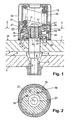
- Fig. 1
- zeigt einen Längsschnitt durch eine erste Ausführungsform eines mit einem trennbaren Türscharnier für Kraftwagentüren baulich vereinigten Türfeststellers;
- Fig. 2
- zeigt einen Schnitt durch den Türfeststeller gemäß Fig.1 entlang der Linie II - II;
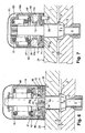
- Fig. 3
- zeigt einen Längsschnitt durch eine zweite Ausführungsform eines mit einem trennbaren Türscharnier für Kraftwagentüren baulich vereinigten Türfeststellers:
- Fig. 4
- zeigt einen Schnitt durch den Türfeststeller gemäß Fig.3 entlang der Linie IV - IV;
- Fig. 5
- zeigt einen Schnitt durch den Türfeststeller gemäß Fig.4 entlang der Linie V - V;
- Fig. 6
- zeigt einen Längsschnitt durch eine dritte Ausführungsform eines mit einem trennbaren Türscharnier für Kraftwagentüren baulich vereinigten Türfeststellers;
- Fig. 7
- zeigt einen Längsschnitt durch eine vierte Ausführungsform eines mit einem trennbaren Türscharnier für Kraftwagentüren baulich vereinigten Türfeststellers.
Die Feststelleinrichtung eines mit dem aushängbaren Türscharnier baulich vereinigten Türfeststellers umfaßt bei allen in der Zeichnung dargestellten Ausführungsformen im Wesentlichen eine durch einen ersten Laufring gebildete, Rastmarken 10 aufweisenden Halteeinrichtung 11, eine Anzahl mit dieser zusammenwirkender Brems-und Haltekörper 12, eine die Brems-und Haltekörper 12 fesselnden Käng 13, und einen glattflächigen zweiten Laufring 14 sowie eine die Brems-und Haltekörper 12 belastende Feder 15. Die Brems-und Feststelleinrichtung ist ferner insgesamt in einem Gehäuse 16 aufgenommen.
Bei der in den Figuren 1 und 2 gezeigten Ausführungsform des Türfeststellers ist die Halteeinrichtung 11 durch einen konzentrisch zum Scharnierstift 3 angeordneten Druckring 17 gebildet, welcher auf den durch konisch gestaltete Wälzkörper gebildeten Brems-und Haltekörpern 12 aufliegend bezüglich des Scharnierstiftes 3 axial verstellbar innerhalb des Gehäuses 16 angeordnet ist. Die Brems-und Haltekörper 12 sind um radial zur Achse des Scharnierstiftes 3 ausgerichtete Achsen rotierbar in den Ausnehmungen 18 des Käfigs 13 geführt. Der glattflächige Laufring 14 ist vermittels eines Wälzlagerringes 19 gegen den Boden 20 des Gehäuses 16 abgestützt. Der Käfig 13 besteht aus einem Flachmaterialzuschnitt und ist vermittels einer Außenumfangsverzahnung 21 einer ihrerseits vermittels einer Axialverzahnung 22 drehsicher mit dem Scharnierstift 3 verbundenen Mitnehmerhülse 23 drehsicher mit dem Scharnierstift 3 verbunden. Das mit seinem Boden 20 auf der außenliegenden Gewerbefläche 24 der Scharnierhälfte 1 aufliegende Gehäuse 16 ist mit der Scharnierhälfte 1 über Zapfen 26 formschlüssig und drehsicher verbunden. Der die Halteeinrichtung 11 bildende bzw. die die Halteeinrichtung bestimmenden Rastmarken 10 aufweisende Druckring 17 ist seinerseits über Gleitführungen zwar formschlüssig drehsicher, aber axial verstellbar mit dem Gehäuse 16 gekoppelt, wobei die Gleitführungen durch achsparallel zum Scharnierstift 3 ausgerichtete, walzenförmige Standardwälzkörper 27 gebildet sind. Die Standardwälzkörper 27 stehen einerseits über in dessen Außenumfangsfläche ausgebildete, kalottenförmige Ausnehmungen 28 mit dem Druckring 17 und andererseits über in dessen Innenumfangsfläche angeordnete radiale Ausbuchtungen 29 mit dem Gehäuse 16 im formschlüssigen Eingriff und weisen eine die Höhe des Druckringes 17 wenigstens um den Betrag der Höhe der Rastmarken der Halteeinrichtung 11 übersteigende axiale Länge auf. Die den Druckring 17 beaufschlagende Belastungsfeder 15 ist durch eine Schraubenfeder gebildet und gegen eine ihrerseits an dem Gehäuse 16 abgestützte Haube 30 abgestützt. Die Haube 30 ist vermittels teilweise umlaufender eigener Randabstellungen 31 an zugehörigen Randabstellungen 32 des freien Randes des Gehäuses 16 abgestützt und befestigt.
Aus der Darstellung der Figur 5 ersichtliche Ausführungsform ist ersichtlich, daß die Rastvertiefungen bzw. Rastmarken 10 der Halteeinrichtung 11 gruppenweise angeordnet sind. wobei jedem Brems-und Haltekörper 12 eine eigene Gruppe von Rastmarken 10 zugeordnet ist. Aus der Darstellung der Figur 4 ist zudem ersichtlich, daß die die Brems-und Haltekörper bildenden Kegelrollen 12 parallel zur Achse des Scharnierstiftes 3 höhenverstellbar in den Ausnehmungen 43 des Käfigs 13 geführt sind.
Die in der Darstellung der Figur 6 gezeigte Ausführungsform unterscheidet sich von derjenigen nach Figur 3 zunächst im Wesentlichen dadurch, daß die die Rastmarken 10 aufweisende Halteeinrichtung 11 als Formteil ausgebildet und unter unmittelbarer Abstützung gegen die obenliegende Gewerbefläche 24 der Scharnierhälfte 1 vermittels einer Innenumfangsverzahnung 44 einer zentralen Ausnehmung drehsicher mit dem Scharnierstift 3 gekoppelt ist und daß in Verbindung mit dieser Anordnung der Halteeinrichtung 11 der die Brems-und Haltekörper 12 führende Käfig 13 drehsicher mit dem Gehäuse 16 verbunden ist. Der Käfig 13 ist hier als Ringscheibe 45 ausgebildet und lediglich über seine Außenumfangswandung 46, z.B. mittels Pressitz, unverschieblich in einer Aufweitung 47 des seinerseits vermittels Zapfen 26 an der Scharnierhälfte 1 befestigten Gehäuses 16 festgelegt. Von der in der Figur 3 gezeigten Ausführungsform unterscheidet sich diejenige nach Figur 6 ferner dadurch, daß der als Druckring wirkende Laufring 39a als massives Formteil ausgebildet und die diesen belastende. als Schraubenfeder ausgebildete Druckfeder 15 gegen den Boden 48 des hier topfförmig ausgebildeten Gehäuses 16 abgestützt ist.
Die in der Figur 7 dargestellte Ausführungsform unterscheidet sich von den Ausführungsformen nach den Figuren 1 bis 6 in der Hauptsache dadurch, daß die die Brems-und Haltekörper bildenden Wälzkörper 12a durch Kugeln gebildet sind. Ein die die Rastmarken 10 aufweisende Halteeinrichtung 11 bildender Laufring ist hier ebenfalls vermittels einer Stützscheibe 33 und eines Lagers 34 gegen die obenliegende Gewerbefläche 24 der Scharnierhälfte 1 abgestützt und vermittels Zapfen 26 formschlüssig und drehsicher mit der Scharnierhälfte 1 verbunden.
Claims (12)
- Mit einem aushängbaren Türscharnier baulich vereinigter Türfeststeller für Kraftwagentüren, wobei das Türscharnier aus einer ersten (1) an einem Türanordnungsteil, Tür oder Türsäule, anschlagbaren und einer zweiten (2) am anderen Türanordnungsteil anschlagbaren Scharnierhälfte (1, 2) sowie einem in der einen Scharnierhälfte (1) mit Laufsitz und in der anderen Scharnierhälfte (2) drehsicher aufgenommenen Scharnierstift (3) besteht und der insgesamt in einem Gehäuse aufgenommene Türfeststeller eine Anzahl als Wälzkörper (12) ausgebildeter, mit einer eine entsprechende Anzahl von Rastmarken (10) aufweisenden Halteeinrichtung (11) zusammenwirkender, um radial zur Scharnierachse gerichtete Achsen rotierbarer Brems- und Haltekörper (12) umfaßt, wobei die die Rastmarken (10) aufweisende Halteeinrichtung (11) als wenigstens teilringförmig gekrümmte und konzentrisch zur Achse des Schanierstiftes (3) angeordnete Laufbahn ausgebildet und drehsicher mit einer der beiden Scharnierhälften (1, 2) verbunden ist und wobei ferner die Brems- und Haltekörper (12) unter einer zu dieser wenigstens annähernd deckungsgleich ausgerichteten Federlast (15) mit der Halteeinrichtung (11) zusammenwirken und wobei ferner in einer zum Schamierstift (3) radialen Ausnehmung achslos in einem Käfig (13) gefesselten, durch Wälzkörper (12) gebildeten Brems-und Haltekörpern einerseits ein glattflächiger Laufring (14) zugeordnet ist,
dadurch gekennzeichnet, daß anderseits die mit Rastmarken (10) versehene Halteeinrichtung (11) auch als Laufring (17) ausgebildet ist, wobei einer der beiden Laufringe (14, 17) mit einer Federlast beaufschlagt ist und wobei der Käfig (13) und der die Halteeinrichtung (11) bildende Laufring (17) wechselweise mit dem Scharnierstift (3) und mit derjenigen Scharnierhälfte (1, 2), in welcher dieser Laufsitz hat, drehsicher verbunden sind. - Türfeststeller nach Anspruch 1, dadurch gekennzeichnet, daß die Brems- und Haltekörper als Kegelrollen (12) ausgebildet und in den Ausnehmungen (18) eines durch einen Flachmaterialzuschnitt gebildeten Käfigs (13) senkrecht zu dessen Ebene verstellbar aufgenommen sind.
- Türfeststeller nach Anspruch 1 oder 2, dadurch gekennzeichnet, daß der Käfig (13) vermittels einer Innenumfangsverzahnung (37) einer zentralen Ausnehmung drehsicher mit dem Scharnierstift (3) verbunden und die mit Rastmarken (10) versehene Halteeinrichtung (11) drehsicher an derjenigen Scharnierhälfte, in welcher der Scharnierstift (3) Laufsitz hat, festgelegt ist.
- Türfeststeller nach einem der Ansprüche 1 bis 3, dadurch gekennzeichnet, daß in Verbindung mit einem gegen die außenliegende Gewerbefläche (24) der einen Scharnierhälfte (1) abstützten glattflächigen Laufring (14) und einem formschlüssig aber axial unverschieblich mit dem Scharnierstift (3) gekoppelten, die die Brems-und Haltekörper bildenden Wälzkörper (12) fesselnden Käfig (13), der die Halteeinrichtung (11) bildende Laufring durch einen mit einer Federlast (15) beaufschlagten Druckring (17) gebildet ist, wobei der Druckring (17) vermittels Gleitführungen bildender Wälzkörper (27) axial verschiebbar, aber drehsicher mit dem an der Scharnlerhälfte (1) festgelegten Gehäuse (16) gekoppelt ist.
- Türfeststeller nach einem der Ansprüche 1 bis 4, dadurch gekennzeichnet, daß der glattflächige Laufring (14) seinerseits vermittels eines Wälzlagers (19) gegen die außenliegende Gewerbefläche (24) der Scharnierhälfte (1) abgestützt ist.
- Türfeststeller nach einem der Ansprüche 1 bis 5, dadurch gekennzeichnet, daß der mit Rastausnehmungen (10) versehene, die Halteeinrichtung (11) bildende Laufring gegen die außenliegende Gewerberfläche (24) der einen Scharnierhälfte abgestützt und drehsicher mit dieser verbunden und der die die Brems- und Haltekörper bildenden Wälzkörper (12) fesselnde Käfig (13) drehsicher mit dem Schamierstift (3) gekoppelt ist und daß der glattflächige Laufring (39) durch einen mit einer Federlast (15) beaufschlagten Druckring gebildet und auf den Brems- und Haltekörpern (12) aufliegend angeordnet ist.
- Türfeststeller nach einem der Ansprüche 1 bis 6, dadurch gekennzeichnet, daß der mit Rastausnehmungen (10) versehene, die Halteeinrichtung (11) bildende, Laufring vermittels einer Umfangsverzahnung (35) drehsicher an dem seinerseits an derjenigen Scharnierhälfte, in welcher der Scharnierstift (3) Laufsitz, hat festgelegten Gehäuse abgestützt ist.
- Türfeststeller nach einem der Ansprüche 1 bis 7, dadurch gekennzeichnet, daß eine als Schraubenfeder (15) ausgebildete Belastungsfeder einerseits gegen das an der Scharnierhälfte (1) festgelegte Gehäuse (16) abgestützt ist und andererseits vermittels eines Druckverteilerringes (41) und eines Wälzlagers (42) den Druckring (39a) beaufschlagt.
- Türfeststeller nach einem der Ansprüche 1 bis 8, dadurch gekennzeichnet, daß in Verbindung mit einem gegen die außenliegende Gewerbefläche (24) der einen Scharnierhälfte (1) abgestützten und drehsicher mit dem Scharnierstift (3) verbundenen, die Halteeinrichtung (11) bildenden Laufring, der die Brems- und Haltekörper (12) fesselnde Käfig (13) drehsicher mit dem an der Scharnierhälfte (1) festgelegten Gehäuse (16) gekoppelt ist und daß ein auf den die Brems- und Haltekörper (12) bildenden Wälzkörpern aufliegender, glattflächiger Druckring (39a) vermittels eines Druckverteilerringes (41) und eines Wälzlagers (42) durch eine gegen das an der Scharnierhälfte (1) festgelegte Gehäuse (16) abgestützte, als Schraubenfeder (15) ausgebildete Belastungsfeder beaufschlagt ist.
- Türfeststeller nach einem der Ansprüche 1 bis 9, dadurch gekennzeichnet, daß die die Brems- und Haltekörper bildenden Wälzkörper als Kugeln (12a) ausgebildet sind.
- Türfeststeller nach einem der Ansprüche 1 bis 10, dadurch gekennzeichnet, daß, in Verbindung mit einem an der außenliegenden Gewerbefläche (24) der einen Scharnierhälfte (1) festgelegten, die Halteeinrichtung (11) bildende Laufring, der die Brems- und Haltekörper (12a) fesselnde Käfig (13) einteilig mit einem drehsicher mit dem Scharnierstift (3) verbundenen, den als Druckring (39) ausgebildeten zweiten Laufring und die Belastungsfeder (15) aufnehmenden Gehäuse (166) ausgebildet ist, wobei das Gehäuse (166) vermittels eines Verzahnungseingriffes (51) drehsicher mit dem freien Ende des Scharnierstiftes (3) verbunden ist (Fig.7).
- Türfeststeller nach einem der Ansprüche 1 bis 11, dadurch gekennzeichnet, daß die die Brems- und Haltekörper bildenden Wälzkörper (12a) aufnehmenden Ausnehmungen (49) des Käfigs (13) durch Freischnitte im Boden (48) des als Blechpressteil ausgebildeten Gehäuses (166) gebildet sind.
Applications Claiming Priority (2)
| Application Number | Priority Date | Filing Date | Title |
|---|---|---|---|
| DE19734841A DE19734841A1 (de) | 1997-08-12 | 1997-08-12 | Mit einem aushängbaren Türscharnier baulich vereinigter Türfeststeller |
| DE19734841 | 1997-08-12 |
Publications (3)
| Publication Number | Publication Date |
|---|---|
| EP0897044A2 EP0897044A2 (de) | 1999-02-17 |
| EP0897044A3 EP0897044A3 (de) | 2000-11-15 |
| EP0897044B1 true EP0897044B1 (de) | 2003-04-02 |
Family
ID=7838699
Family Applications (1)
| Application Number | Title | Priority Date | Filing Date |
|---|---|---|---|
| EP98115069A Expired - Lifetime EP0897044B1 (de) | 1997-08-12 | 1998-08-11 | Mit einem aushängbaren Türscharnier baulich vereinigter Türfeststeller |
Country Status (6)
| Country | Link |
|---|---|
| US (1) | US6029314A (de) |
| EP (1) | EP0897044B1 (de) |
| JP (1) | JPH11107610A (de) |
| CN (1) | CN1215124A (de) |
| AR (1) | AR016609A1 (de) |
| DE (2) | DE19734841A1 (de) |
Families Citing this family (14)
| Publication number | Priority date | Publication date | Assignee | Title |
|---|---|---|---|---|
| DE10118301B4 (de) | 2001-04-12 | 2011-01-20 | Brückner, Lothar, Dr. | Kraftwagentürscharnier |
| DE19854602A1 (de) * | 1998-11-26 | 2000-06-08 | Scharwaechter Ed Gmbh | An ein Türscharnier angeschlossener Türfeststeller für Kraftwagentüren |
| IT1320288B1 (it) * | 2000-03-29 | 2003-11-26 | Gammastamp Spa | Cerniera per porte di veicoli con dispositivo fermaporta integrato. |
| KR20020078892A (ko) * | 2001-04-11 | 2002-10-19 | 현대자동차주식회사 | 자동차의 도어 힌지 |
| US6607236B2 (en) | 2001-12-05 | 2003-08-19 | Ventra Group Inc. | Door support system |
| DE10203056B4 (de) * | 2002-01-26 | 2008-09-18 | Ab Skf | Scharnierkartusche für ein Türscharnier |
| DE10343587B4 (de) * | 2003-09-18 | 2005-09-01 | Ise Innomotive Systems Europe Gmbh | Türscharnier mit Feststeller für Kraftfahrzeugtüren |
| US20050125950A1 (en) * | 2003-12-10 | 2005-06-16 | Ding-Hone Su | Hinge with a rotating function |
| EP2011942A1 (de) * | 2007-07-03 | 2009-01-07 | Wagon Automotive GmbH | Unendlich variierbarer Türfeststeller |
| DE102010015064B4 (de) * | 2010-04-15 | 2012-09-06 | D. la Porte Söhne GmbH | Feststeller für eine Fahrzeugtür oder -klappe |
| WO2018083021A1 (en) | 2016-11-01 | 2018-05-11 | Saint-Gobain Performance Plastics Rencol Limited | Friction brake |
| US10267075B2 (en) * | 2017-05-01 | 2019-04-23 | Nio Usa, Inc. | Self-contained door hinge mechanism |
| CN107916857B (zh) * | 2017-11-21 | 2019-04-05 | 中南大学 | 一种车门铰链固定支座自动分离系统及方法 |
| EP3805497B1 (de) * | 2019-10-10 | 2022-06-22 | MAGNA STEYR Fahrzeugtechnik AG & Co KG | Türhalteranordnung |
Family Cites Families (6)
| Publication number | Priority date | Publication date | Assignee | Title |
|---|---|---|---|---|
| DE8627459U1 (de) * | 1986-10-15 | 1987-11-19 | Lunke & Sohn Gmbh, 5810 Witten | Türscharnier für eine Fahrzeugtür |
| DE8904337U1 (de) * | 1989-04-07 | 1990-09-27 | Lunke & Sohn Gmbh, 5810 Witten | Scharnier für eine Kraftfahrzeugtür |
| US5173993A (en) * | 1991-10-30 | 1992-12-29 | Unlimited Ideas And Designs Inc. | Adjustable locking door hinge |
| DE29614379U1 (de) * | 1996-08-20 | 1996-10-24 | Ed. Scharwächter GmbH + Co KG, 42855 Remscheid | Mit einem aushängbaren Türscharnier baulich vereinigter Türfeststeller |
| EP0825318B1 (de) * | 1996-08-20 | 2000-11-08 | ED. Scharwächter GmbH | Mit einem aushängbaren Türscharnier baulich vereinigter Türfeststeller |
| DE29700043U1 (de) * | 1996-12-10 | 1997-03-13 | ED. Scharwächter GmbH & Co. KG, 42855 Remscheid | Türfeststeller für Kraftwagentüren |
-
1997
- 1997-08-12 DE DE19734841A patent/DE19734841A1/de not_active Withdrawn
-
1998
- 1998-08-11 JP JP10227359A patent/JPH11107610A/ja not_active Withdrawn
- 1998-08-11 EP EP98115069A patent/EP0897044B1/de not_active Expired - Lifetime
- 1998-08-11 DE DE59807701T patent/DE59807701D1/de not_active Expired - Lifetime
- 1998-08-12 AR ARP980103991A patent/AR016609A1/es unknown
- 1998-08-12 CN CN98117163A patent/CN1215124A/zh active Pending
- 1998-08-12 US US09/133,092 patent/US6029314A/en not_active Expired - Lifetime
Also Published As
| Publication number | Publication date |
|---|---|
| AR016609A1 (es) | 2001-07-25 |
| US6029314A (en) | 2000-02-29 |
| DE19734841A1 (de) | 1999-02-18 |
| EP0897044A2 (de) | 1999-02-17 |
| DE59807701D1 (de) | 2003-05-08 |
| EP0897044A3 (de) | 2000-11-15 |
| JPH11107610A (ja) | 1999-04-20 |
| CN1215124A (zh) | 1999-04-28 |
Similar Documents
| Publication | Publication Date | Title |
|---|---|---|
| EP0897044B1 (de) | Mit einem aushängbaren Türscharnier baulich vereinigter Türfeststeller | |
| EP0207182B1 (de) | Drehgelenk für Sitze mit verstellbarer Rückenlehne | |
| EP0274584B1 (de) | Vorrichtung zum Abdichten der Lagerbüchse eines Kreuzgelenkes | |
| DE69101303T2 (de) | Elastisches Gleitlager und seine Verwendung für Automobillenkungen. | |
| DE3522461A1 (de) | Halterung von laufringen | |
| EP2391832B1 (de) | Gleichlaufdrehgelenk mit verbesserten montageeigenschaften | |
| EP0807738A2 (de) | Mit einem aushängbaren Türscharnier baulich vereinigter Türfeststeller | |
| DE69114224T2 (de) | Kombiniertes Axial-Radiallager. | |
| DE3723710A1 (de) | Drehgelenk fuer sitze mit verstellbarer rueckenlehne | |
| DE19727098C2 (de) | Mit einem aushängbaren Türscharnier baulich vereinigter Türfeststeller | |
| EP0897045B1 (de) | Mit einem aushängbaren Türscharnier baulich vereinigter Türfeststeller | |
| DE102019210891A1 (de) | Drehbeschlag mit einer Exzenterbaugruppe | |
| EP0518091A1 (de) | Teleskopische Lenkwelle für Kraftfahrzeuge | |
| EP0848128A2 (de) | Türfeststeller für Kraftwagentüren | |
| DE10134355A1 (de) | Verstellbeschlag für Kraftfahrzeugsitze | |
| DE19633462B4 (de) | Scharnier für eine Fahrzeugtür | |
| DE102010051497B4 (de) | Fahrzeugsitz, insbesondere Kraftfahrzeugsitz | |
| EP2391833B1 (de) | GLEICHLAUFDREHGELENK MiT VERBESSERTEN MONTAGEEIGENSCHAFTEN | |
| DE29714408U1 (de) | Mit einem aushängbaren Türscharnier baulich vereinigter Türfeststeller | |
| EP0436066B1 (de) | Scharniergelenklagerung für Kraftfahrzeuge | |
| DE10203006A1 (de) | Beschlag für einen Fahrzeugsitz | |
| DE19727041C2 (de) | Mit einem aushängbaren Türscharnier baulich vereinigter Türfeststeller | |
| DE102007036537B4 (de) | Gelenkbeschlag eines Kraftfahrzeugsitzes | |
| DE102004044753A1 (de) | Neigungsverstellbeschlag für die Rückenlehne eines Kraftfahrzeugsitzes | |
| DE29614385U1 (de) | Mit einem aushängbaren Türscharnier baulich vereinigter Türfeststeller |
Legal Events
| Date | Code | Title | Description |
|---|---|---|---|
| PUAI | Public reference made under article 153(3) epc to a published international application that has entered the european phase |
Free format text: ORIGINAL CODE: 0009012 |
|
| 17P | Request for examination filed |
Effective date: 19980811 |
|
| AK | Designated contracting states |
Kind code of ref document: A2 Designated state(s): DE ES FR GB IT NL PT SE |
|
| AX | Request for extension of the european patent |
Free format text: AL;LT;LV;MK;RO;SI |
|
| PUAL | Search report despatched |
Free format text: ORIGINAL CODE: 0009013 |
|
| AK | Designated contracting states |
Kind code of ref document: A3 Designated state(s): AT BE CH CY DE DK ES FI FR GB GR IE IT LI LU MC NL PT SE |
|
| AX | Request for extension of the european patent |
Free format text: AL;LT;LV;MK;RO;SI |
|
| AKX | Designation fees paid |
Free format text: DE ES FR GB IT NL PT SE |
|
| GRAH | Despatch of communication of intention to grant a patent |
Free format text: ORIGINAL CODE: EPIDOS IGRA |
|
| GRAH | Despatch of communication of intention to grant a patent |
Free format text: ORIGINAL CODE: EPIDOS IGRA |
|
| GRAA | (expected) grant |
Free format text: ORIGINAL CODE: 0009210 |
|
| AK | Designated contracting states |
Designated state(s): DE ES FR GB IT NL PT SE |
|
| PG25 | Lapsed in a contracting state [announced via postgrant information from national office to epo] |
Ref country code: NL Free format text: LAPSE BECAUSE OF FAILURE TO SUBMIT A TRANSLATION OF THE DESCRIPTION OR TO PAY THE FEE WITHIN THE PRESCRIBED TIME-LIMIT Effective date: 20030402 Ref country code: IT Free format text: LAPSE BECAUSE OF FAILURE TO SUBMIT A TRANSLATION OF THE DESCRIPTION OR TO PAY THE FEE WITHIN THE PRESCRIBED TIME-LIMIT;WARNING: LAPSES OF ITALIAN PATENTS WITH EFFECTIVE DATE BEFORE 2007 MAY HAVE OCCURRED AT ANY TIME BEFORE 2007. THE CORRECT EFFECTIVE DATE MAY BE DIFFERENT FROM THE ONE RECORDED. Effective date: 20030402 Ref country code: GB Free format text: LAPSE BECAUSE OF FAILURE TO SUBMIT A TRANSLATION OF THE DESCRIPTION OR TO PAY THE FEE WITHIN THE PRESCRIBED TIME-LIMIT Effective date: 20030402 Ref country code: FR Free format text: LAPSE BECAUSE OF FAILURE TO SUBMIT A TRANSLATION OF THE DESCRIPTION OR TO PAY THE FEE WITHIN THE PRESCRIBED TIME-LIMIT Effective date: 20030402 |
|
| REG | Reference to a national code |
Ref country code: GB Ref legal event code: FG4D Free format text: NOT ENGLISH |
|
| REF | Corresponds to: |
Ref document number: 59807701 Country of ref document: DE Date of ref document: 20030508 Kind code of ref document: P |
|
| PG25 | Lapsed in a contracting state [announced via postgrant information from national office to epo] |
Ref country code: SE Free format text: LAPSE BECAUSE OF FAILURE TO SUBMIT A TRANSLATION OF THE DESCRIPTION OR TO PAY THE FEE WITHIN THE PRESCRIBED TIME-LIMIT Effective date: 20030702 Ref country code: PT Free format text: LAPSE BECAUSE OF FAILURE TO SUBMIT A TRANSLATION OF THE DESCRIPTION OR TO PAY THE FEE WITHIN THE PRESCRIBED TIME-LIMIT Effective date: 20030702 |
|
| NLV1 | Nl: lapsed or annulled due to failure to fulfill the requirements of art. 29p and 29m of the patents act | ||
| GBV | Gb: ep patent (uk) treated as always having been void in accordance with gb section 77(7)/1977 [no translation filed] |
Effective date: 20030402 |
|
| PG25 | Lapsed in a contracting state [announced via postgrant information from national office to epo] |
Ref country code: ES Free format text: LAPSE BECAUSE OF FAILURE TO SUBMIT A TRANSLATION OF THE DESCRIPTION OR TO PAY THE FEE WITHIN THE PRESCRIBED TIME-LIMIT Effective date: 20031030 |
|
| PLBE | No opposition filed within time limit |
Free format text: ORIGINAL CODE: 0009261 |
|
| STAA | Information on the status of an ep patent application or granted ep patent |
Free format text: STATUS: NO OPPOSITION FILED WITHIN TIME LIMIT |
|
| EN | Fr: translation not filed | ||
| 26N | No opposition filed |
Effective date: 20040105 |
|
| REG | Reference to a national code |
Ref country code: DE Ref legal event code: R082 Ref document number: 59807701 Country of ref document: DE Representative=s name: BONNEKAMP & SPARING, DE Effective date: 20110812 Ref country code: DE Ref legal event code: R081 Ref document number: 59807701 Country of ref document: DE Owner name: EDSCHA ENGINEERING GMBH, DE Free format text: FORMER OWNER: ED. SCHARWAECHTER GMBH, 42855 REMSCHEID, DE Effective date: 20110812 |
|
| PGFP | Annual fee paid to national office [announced via postgrant information from national office to epo] |
Ref country code: DE Payment date: 20170822 Year of fee payment: 20 |
|
| REG | Reference to a national code |
Ref country code: DE Ref legal event code: R071 Ref document number: 59807701 Country of ref document: DE |