EP0896342B1 - Isolierter Draht mit Rauschunterdrückung - Google Patents
Isolierter Draht mit Rauschunterdrückung Download PDFInfo
- Publication number
- EP0896342B1 EP0896342B1 EP98114747A EP98114747A EP0896342B1 EP 0896342 B1 EP0896342 B1 EP 0896342B1 EP 98114747 A EP98114747 A EP 98114747A EP 98114747 A EP98114747 A EP 98114747A EP 0896342 B1 EP0896342 B1 EP 0896342B1
- Authority
- EP
- European Patent Office
- Prior art keywords
- noise
- wire
- insulated wire
- suppressing function
- function according
- Prior art date
- Legal status (The legal status is an assumption and is not a legal conclusion. Google has not performed a legal analysis and makes no representation as to the accuracy of the status listed.)
- Expired - Lifetime
Links
- 239000006247 magnetic powder Substances 0.000 claims description 45
- 239000011248 coating agent Substances 0.000 claims description 24
- 238000000576 coating method Methods 0.000 claims description 24
- 239000000463 material Substances 0.000 claims description 9
- 229920005989 resin Polymers 0.000 claims description 8
- 239000011347 resin Substances 0.000 claims description 8
- 229910018605 Ni—Zn Inorganic materials 0.000 claims description 7
- 229920001971 elastomer Polymers 0.000 claims description 7
- 239000002245 particle Substances 0.000 claims description 5
- 230000037431 insertion Effects 0.000 claims 1
- 238000003780 insertion Methods 0.000 claims 1
- 230000000694 effects Effects 0.000 description 15
- 229910000859 α-Fe Inorganic materials 0.000 description 9
- 238000000034 method Methods 0.000 description 5
- 238000009413 insulation Methods 0.000 description 4
- 230000035699 permeability Effects 0.000 description 4
- BZHJMEDXRYGGRV-UHFFFAOYSA-N Vinyl chloride Chemical compound ClC=C BZHJMEDXRYGGRV-UHFFFAOYSA-N 0.000 description 3
- 239000000843 powder Substances 0.000 description 3
- 238000001746 injection moulding Methods 0.000 description 2
- 238000000465 moulding Methods 0.000 description 2
- RYGMFSIKBFXOCR-UHFFFAOYSA-N Copper Chemical compound [Cu] RYGMFSIKBFXOCR-UHFFFAOYSA-N 0.000 description 1
- 239000000919 ceramic Substances 0.000 description 1
- 238000013016 damping Methods 0.000 description 1
- 238000004519 manufacturing process Methods 0.000 description 1
- 229910052751 metal Inorganic materials 0.000 description 1
- 239000002184 metal Substances 0.000 description 1
- 239000004576 sand Substances 0.000 description 1
- 230000001629 suppression Effects 0.000 description 1
- 229920002803 thermoplastic polyurethane Polymers 0.000 description 1
Images


Classifications
-
- H—ELECTRICITY
- H01—ELECTRIC ELEMENTS
- H01B—CABLES; CONDUCTORS; INSULATORS; SELECTION OF MATERIALS FOR THEIR CONDUCTIVE, INSULATING OR DIELECTRIC PROPERTIES
- H01B11/00—Communication cables or conductors
- H01B11/02—Cables with twisted pairs or quads
- H01B11/12—Arrangements for exhibiting specific transmission characteristics
- H01B11/16—Cables, e.g. submarine cables, with coils or other devices incorporated during cable manufacture
Definitions
- the present invention relates to an insulated wire with a noise-suppressing function, and more particularly, to an insulated wire with a noise-suppressing function used for a signal line.
- FIG. 9 A known method for suppressing high-frequency noise which has entered a signal line is shown in Fig. 9.
- two divided core pieces 81a and 81b are accommodated in a cylindrical case 82 which can be divided into two sections.
- An insulated wire 83 is sand wiched by the two core pieces 81a and 81b.
- a ring-shaped magnetic core 81 formed by the divided core pieces 81a and 81b is secured to the periphery of the insulated wire 83 by the use of case fasteners 82a and 82b provided for the case 82.
- An advantage of this method is that the ring-shaped magnetic core 81 can be easily placed on the insulated wire 83 afterwards.
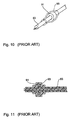
- FIGs. 10 and 11 Another known method is shown in Figs. 10 and 11, in which an insulated wire 83 is inserted into a ring-shaped magnetic core 91 and the ring-shaped magnetic core 91 is covered by a resin material 93 to secure the core to the insulated wire 83.
- An advantage of this method is that the user cannot easily remove the ring-shaped core 91 from the insulated wire 83 and this ensures that high-frequency noise is positively suppressed.
- an object of the present invention to provide an insulated wire with a noise-suppressing function, in which a ring-shaped magnetic core can be made more compact and lightweight.
- the foregoing object is achieved according to the present invention through a provision of an insulated wire with a noise-suppressing function, wherein a part of a coated wire where a coating member is removed is inserted into a ring-shaped magnetic core having an inner diameter smaller than the outer diameter of the coated wire.
- a securing member made from at least one of either resin or rubber secures the ring-shaped magnetic core to the coated wire.
- the coating member of the coated wire may be removed in the radial direction of the wire at least in part. It is not necessary for the whole coating member to be removed.
- the present invention since a part of a coated wire where a coating member is removed is inserted into a ring-shaped magnetic core having a smaller inner diameter than the outer diameter of the coated wire, the same noise-suppressing effect as in the conventional configuration is obtained with a more compact and more lightweight ring-shaped magnetic core than in the conventional configuration, and the cost is reduced because of a reduction in the amount of the material of a magnetic member.
- the impedance of a ring-shaped magnetic core is proportional to (outer diameter - inner diameter)/(outer diameter + inner diameter), with the impedance being the same, if the inner diameter is set smaller than before, the outer diameter is relatively made smaller. Therefore, the same noise-suppressing capability as in the conventional configuration is obtained with a smaller-sized ring-shaped magnetic core.
- a securing member made from at least one of either resin or rubber includes magnetic powder
- noise-suppressing effects are obtained by the securing member having the magnetic powder as well as by the ring-shaped magnetic core. Since a securing member that includes magnetic powder has a stronger noise-suppressing effect than a ring-shaped magnetic core in a high-frequency band (GHz band), the insulated wire with the noise-suppressing function can suppress noise in a wide frequency band.
- GHz band high-frequency band
- the ring-shaped magnetic core When the ring-shaped magnetic core is formed of a plurality of divided core pieces, it can be mounted on the insulated wire at any position. As a result, there are no limitations where the ring-shaped magnetic core can be mounted along the length of the wire.
- the size of the ring-shaped magnetic core can be made small, when a securing bushing is formed of a securing member made from at least one of either resin or rubber and including magnetic powder, the securing member including the magnetic powder, in which the ring-shaped magnetic core is housed, is only slightly larger in size than a conventional securing bushing without a magnetic core, and the size is not noticeably increased even with the ring-shaped magnetic core.
- a noise-suppressing function is obtained in a wide frequency band with the use of the ring-shaped magnetic core and the securing member having the magnetic powder. As a result, the portion where the ring-shaped magnetic core is mounted does not serve as an obstacle, and the insulated wire with a noise-suppressing function can be handled easily.
- Figs. 1 and 2 show an insulated wire 1 with a noise-suppressing function according to a first embodiment of the present invention. It includes a ring-shaped magnetic core 2, an insulated wire 5 passing through the hole 2a of the ring-shaped magnetic core 2, and a securing member 10 for securing the ring-shaped magnetic core 2 to the insulated wire 5.
- the inner diameter of the ring-shaped magnetic core 2, namely the diameter of the hole 2a is set smaller than the outer diameter of the insulated wire 5.
- the material of the ring-shaped magnetic core 2 is, for example, Ni-Zn ferrite, Mn-Zn ferrite, or Mg-Zn ferrite. In the first embodiment, Ni-Zn ceramic ferrite having a relative magnetic permeability of about 500 is used.
- the insulated wire 5 is formed of a pair of conductive wires 6 disposed in parallel to each other, a wire-coating member 7 for coating the pair of conductive wires 6, and a sheath 8 for coating the wire-coating member 7.
- Copper wire or soldered wire for example, is used for the conductive wires 6.
- Vinyl chloride or urethane resin for example, is used for the wire-coating member 7 and the sheath 8.
- the term "sheath" used herein is broad, meaning any coating member which is disposed around the wires 6.
- the sheath 8 is removed at one end of the insulated wire 5. A part of the conductive wires 6, coated only with the wire-coating member 7, is inserted into the hole 2a of the ring-shaped magnetic core 2.
- the ring-shaped magnetic core 2 is disposed in the vicinity of the end of the sheath 8 and is secured to the end of the insulated wire 5 by placing the securing member 10 thereon.
- At least one of either resin or rubber is used for the securing member 10. Since resin and rubber are flexible, they also function as a damping material against mechanical stress applied to the ring-shaped magnetic core 2.
- vinyl chloride or like material is used for the securing member 10.
- the sheath 8 is removed at one end of the insulated wire 5 and the end of the insulated wire 5 is inserted into a ring-shaped magnetic core 2 having a smaller inner diameter than the conventional core. Since the impedance of the ring-shaped magnetic core 2 is proportional to (D1 - D2) / (D1 + D2), where D1 indicates the outer diameter of the ring-shaped magnetic core 2 and D2 indicates the inner diameter, with the impedance being the same, if the inner diameter can be made smaller than the conventional inner diameter, the outer diameter is also made relatively smaller.
- the outer diameter can also be set to two-thirds the conventional outer diameter.
- the volume of the ring-shaped magnetic core becomes one-half the conventional volume or less. Therefore, the same noise-suppressing capability as in the conventional configuration can be obtained with the ring-shaped magnetic core 2 having a smaller size than the conventional configuration. Further, when a ring-shaped magnetic core 2 having the same outer diameter as the conventional outer diameter is used, an insulated wire 1 with a noise-suppressing function having a better noise-suppressing capability than the conventional configuration can be obtained.
- Fig. 3 is a graph indicating the impedance characteristics of an insulated wire 1 with a noise-suppressing function measured when a high-frequency signal having a frequency ranging from 1 MHz to 1000 MHz Is applied to the pair of wires 6 in the insulated wire 1 in the same direction.
- the solid line 15 corresponds to a case in which the ring-shaped magnetic core 2 has an inner diameter of 5.6 mm, an outer diameter of 10 mm, a width of 15 mm, and a volume of about 0.8 cm 3 .
- the two-dot chain line 16 corresponds to a case in which the ring-shaped magnetic core 2 has an inner diameter of 5.6 mm, an outer diameter of 16 mm, and a width of 15 mm.
- the dotted line 17 indicates the impedance characteristic of a wire having the conventional structure shown in Fig. 11 (in which the ring-shaped magnetic core has an inner diameter of 9 mm, an outer diameter of 16 mm, a width of 15 mm, and a volume of about 2.0 cm 3 ).
- the solid line 15 and the dotted line 17 show substantially the same impedance characteristic in Fig. 3. Therefore, it is understood that the insulated wire 1 with the noise-suppressing function according to the first embodiment has the same impedance characteristic as the conventional wire, even with the ring-shaped magnetic core 2 having a smaller size (about 40% in volume) than the conventional core.
- the two-dot chain line 16 shows a larger impedance than the dotted line 17. Therefore, it is understood that the insulated wire 1 with the noise-suppressing function according to the first embodiment has a larger impedance than the conventional wire when the ring-shaped magnetic core 2 has the same outer diameter as the conventional core.
- the securing member 10 When the securing member 10 includes magnetic powder, a noise-suppressing effect due to the securing member 10 having the magnetic powder is obtained in addition to that due to the ring-shaped magnetic core 2. Since the securing member 10 having the magnetic powder has a stronger noise-suppressing effect than the ring-shaped magnetic core 2 in a high frequency band (GHz band), the insulated wire 1 with the noise-suppressing function suppresses noise in a wide frequency band by the use of the securing member 10 having the magnetic powder.
- a noise-suppressing effect due to the securing member 10 having the magnetic powder Since the securing member 10 having the magnetic powder has a stronger noise-suppressing effect than the ring-shaped magnetic core 2 in a high frequency band (GHz band), the insulated wire 1 with the noise-suppressing function suppresses noise in a wide frequency band by the use of the securing member 10 having the magnetic powder.
- the magnetic powder included in the securing member 10 is set such that it has an average particle diameter of about 1 to 100 ⁇ m and a content of about 20 to 70 percent by volume of the securing member 10. This is because of the fact that, if the magnetic powder has an average particle diameter of more than about 100 ⁇ m, it is difficult to knead the powder with resin or rubber, and if the magnetic powder has an average particle diameter of less than about 1 ⁇ m, a required magnetic permeability cannot be obtained. This is also because, if the magnetic-powder content becomes less than about 20 percent by volume, a required magnetic permeability cannot be obtained.
- the securing member 10 have a magnetic-powder content of 20 to 70 percent by volume to form as a unit the securing member 10 on the ring-shaped magnetic core 2 and the insulated wire 5 by cast molding or injection molding.
- the manufacturing method for the securing member 10 is not limited to cast molding or injection molding.
- Ni-Zn or Mg-Zn ferrite magnetic powder having a high resistivity or Mn-Zn ferrite magnetic powder having a low resistivity and magnetic metal powder having a low resistivity is used as the magnetic powder.
- the one-dot chain line 18 shown in Fig. 3 indicates an impedance characteristic in an embodiment in which Ni-Zn ferrite powder having an average particle diameter of 20 ⁇ m kneaded with vinyl chloride so as to have a content of 60 per cent by volume (at a relative magnetic permeability of about 15) is used for the securing member 10 having magnetic powder, and the ring-shaped magnetic core 2 has an inner diameter of 5.6 mm, an outer diameter of 10 mm, and a width of 15 mm.
- the impedance in dicated by the one-dot chain line 18 is larger than that indicated by the solid line 15, in the GHz band. Therefore, it is understood that the noise-suppressing effect is improved in a high-frequency band when the magnetic powder is included in the securing member 10.
- Fig. 4 shows an insulated wire 21 with a noise-suppressing function according to a second embodiment of the present invention. It has the same structure as in the first embodiment except that a wire-coating member 7 is removed together with a sheath 8 at one end of an insulated wire 5. A pair of exposed conductive wires 6 without the wire-coating member 7 is inserted into the hole 2a of a ring-shaped magnetic core 2. The ring-shaped magnetic core 2 is disposed in the vicinity of the wire-coating member 7 and the sheath 8, and secured to the end of the insulated wire 5 with a securing member 22 being placed on the core 2.
- the insulated wire 21 with the noise-suppressing function having the above structure achieves the same functions and advantages as the insulated wire 1 with the noise-suppressing function according to the first embodiment.
- the securing member 22 includes magnetic powder in the same way as in the first embodiment, a noise-suppressing effect due to the securing member 22 having the magnetic powder is obtained in addition to that due to the ring-shaped magnetic core 2.
- the securing member 10 having the magnetic powder may have a low degree of insulation.
- the wire-coating member 7 and the sheath 8 are removed as in the second embodiment, it is necessary to ensure insulation between the conductive wires 6, with the securing member 22 having the magnetic powder being placed around the wire. Therefore, Ni-Zn or Mg-Zn ferrite magnetic powder having a high resistivity is used for the magnetic powder included in the securing member 22.
- Figs. 5 and 6 show an insulated wire 31 with a noise-suppressing function according to a third embodiment of the present invention. It includes a ring-shaped magnetic core 32, a coated wire 5 passing through the hole 32c of the ring-shaped magnetic core 32, and a securing member 37 for securing the ring-shaped magnetic core 32 to the coated wire 5.
- the ring-shaped magnetic core 32 is formed of two divided core pieces 32a and 32b.
- the inner diameter of the ring-shaped magnetic core 32 namely the diameter of the hole 32c, is set smaller than the outer diameter of the coated wire 5.
- a sheath 8 is removed from the coated wire 5 at a position a certain distance away from one end.
- the divided core pieces 32a and 32b are disposed such that they sandwich a portion of conductive wires 6, which are coated only with the wire-coating member 7.
- the divided core pieces 32a and 32b butt against each other to form the ring-shaped magnetic core 32.
- the insulated wire 31 with the noise-suppressing function having the above structure achieves the same functions and advantages as the insulated wire 1 with the noise-suppressing function described in the first embodiment, and in addition, the ring-shaped magnetic core 32 can be mounted at any position on the insulated wire 31 to provide the noise-suppressing function. Therefore, it is not necessary to mount the ring-shaped magnetic core to an end of the insulated wire 31 to provide the noise-suppressing function.
- the ends of the wire may have a normal structure and it becomes easy to handle the wire 31 when the wire is connected to a component.
- the securing member 37 may include magnetic powder so that a noise-suppressing effect due to the securing member 37 having the magnetic powder is also obtained in addition to a noise-suppressing effect due to the ring-shaped magnetic core 32.
- Fig. 7 shows an insulated wire 41 with a noise-suppressing function according to a fourth embodiment of the present invention. It has the same structure as in the third embodiment except that a wire-coating member 7 is removed together with a sheath 8 at a position a certain distance away from one end of a coated wire 5. An exposed part of a pair of conductive wires 6 without the wire-coating member 7 is inserted into the hole 32c of a ring-shaped magnetic core 32.
- the ring-shaped magnetic core 32 is formed of two divided core pieces 32a and 32b (the divided core piece 32a is not shown in Fig. 7).
- the ring-shaped magnetic core 32 is covered by a securing member 43 and secured to the coated wire 5.
- the insulated wire 41 with the noise-suppressing function having the above structure achieves the same functions and advantages as the insulated wire 31 with the noise-suppressing function described in the third embodiment.
- the securing member 43 may include magnetic powder so that a noise-suppressing effect (including a normal-mode noise-suppressing effect) due to the securing member 43 having magnetic powder is also obtained.
- Ni-Zn or Mg-Zn ferrite (or like material) magnetic powder having a high resistivity is used for the magnetic powder in order to ensure insulation between the conductive wires 6.
- Fig. 8 shows an insulated wire 51 with a noise-suppressing function according to a fifth embodiment of the present invention. It uses a securing member 53 both for securing a ring-shaped magnetic core 32 to a coated wire 5 and as a securing bushing used for mounting the coated wired 5 to the case of an electronic unit.
- a sheath 8 is removed from the coated wire 5 at a position a certain distance away from one end.
- Divided core pieces 32a and 32b are disposed such that they sandwich a portion of conductive wires 6, which are coated only with a wire-coating member 7.
- the divided core pieces 32a and 32b butt against each other to form the ring-shaped magnetic core 32.
- the securing member 53 includes magnetic powder, a noise-suppressing effect due to the securing member 53 having the magnetic powder is also obtained in addition to a noise-suppressing effect due to the ring-shaped magnetic core 32. Therefore, the insulated wire 51 with the noise-suppressing function which can suppress noise in a wide frequency band is obtained.
- the securing member 53 is provided with a securing flange 54 at one end. The securing flange 54 is pressed into a hole 61 of the case 60 of an electronic unit so that the securing member 53 is hooked at the hole 61 by a narrow portion 55. The securing member thus works as a securing bushing.
- the insulated wire 51 with the noise-suppressing function having the above structure achieves the same functions and the same advantages as in the third embodiment. Since the size of the ring-shaped magnetic core 32 is smaller than the conventional ring-shaped magnetic core, the securing member 53 having the magnetic powder, in which the ring-shaped magnetic core 32 is housed, is only slightly larger in size than a conventional securing bushing without a magnetic core, and the size is not noticeably increased even with the ring-shaped magnetic core. The insulated wire 51 with the noise-suppressing function is, there fore, easily handled.
- an insulated wire with a noise-suppressing function is not limited to the above exemplary embodiments.
- the ring-shaped magnetic core is not limited to a circular ring. It may be a rectangular ring.
Landscapes
- Coils Or Transformers For Communication (AREA)
- Shielding Devices Or Components To Electric Or Magnetic Fields (AREA)
- Communication Cables (AREA)
Claims (18)
- Ein isolierter Draht (1; 21; 31; 41; 51) mit einer Rauschunterdrückungsfunktion, der folgende Merkmale aufweist:wobei der ringförmige Magnetkern (2) einen Innendurchmesser aufweist, der geringer ist als der Außendurchmesser der Umhüllung (8).einen Draht (5);eine Umhüllung (8), die einen Außendurchmesser aufweist und um den Draht (5) herum angeordnet ist, mit Ausnahme zumindest eines Abschnitts entlang der Länge des Drahtes (5), an dem die Umhüllung (8) entfernt ist;einen ringförmigen Magnetkern (2; 32), der an dem Abschnitt, an dem die Umhüllung (8) entfernt ist, um den Draht (5) herum angeordnet ist; undein Befestigungsbauglied (10; 22; 37; 43), das den ringförmigen Magnetkern (2) an dem Abschnitt befestigt;
- Der isolierte Draht mit einer Rauschunterdrückungsfunktion gemäß Anspruch 1,
bei dem sich der Abschnitt, an dem die Umhüllung (8) entfernt ist, an einem distalen Ende des Drahtes befindet. - Der isolierte Draht mit einer Rauschunterdrückungsfunktion gemäß Anspruch 1,
bei dem sich der Abschnitt, an dem die Umhüllung (8) entfernt ist, zwischen zwei Teilstücken des Drahtes (5), der die um den Draht (5) angeordnete Umhüllung (8) aufweist, befindet. - Der isolierte Draht mit einer Rauschunterdrückungsfunktion gemäß einem der Ansprüche 1 bis 3, der ferner ein Drahtbeschichtungsbauglied (7) zwischen dem Draht und der Umhüllung umfaßt.
- Der isolierte Draht mit einer Rauschunterdrückungsfunktion gemäß Anspruch 4, bei dem das Drahtbeschichtungsbauglied (7) an dem Abschnitt vorliegt, an dem die Umhüllung (8) entfernt ist.
- Der isolierte Draht mit einer Rauschunterdrückungsfunktion gemäß Anspruch 4, bei dem das Drahtbeschichtungsbauglied (7) an dem Abschnitt entfernt ist, an dem die Umhüllung (8) entfernt ist, wobei das Befestigungsbauglied (22) den Magnetkern (32) von dem Draht trennt.
- Der isolierte Draht mit einer Rauschunterdrückungsfunktion gemäß einem der Ansprüche 1 bis 6, bei dem der ringförmige Magnetkern (32) durch eine Mehrzahl von geteilten Kernstücken (32a, 32b) gebildet ist.
- Der isolierte Draht mit einer Rauschunterdrückungsfunktion gemäß einem der Ansprüche 1 bis 7, bei dem das Befestigungsbauglied (53) aufgebaut ist, um als Hülse zu dienen.
- Der isolierte Draht mit einer Rauschunterdrückungsfunktion gemäß Anspruch 8, bei dem das Befestigungsbauglied (53) ferner einen Flansch (54) umfaßt, der für eine Einfügung in ein Loch (61) in einem Gehäuse (60) einer elektronischen Einheit vorgesehen ist.
- Der isolierte Draht mit einer Rauschunterdrückungsfunktion gemäß Anspruch 9, bei dem das Befestigungsbauglied (53) ferner einen schmalen Abschnitt umfaßt, der Ränder des Loches (61) in Eingriff nimmt.
- Der isolierte Draht mit einer Rauschunterdrückungsfunktion gemäß einem der Ansprüche 1 bis 10, bei dem das Befestigungsbauglied (10; 22; 37; 43) zumindest entweder aus Harz oder Gummi hergestellt ist.
- Der isolierte Draht mit einer Rauschunterdrückungsfunktion gemäß einem der Ansprüche 1 bis 11, bei dem das Befestigungsbauglied (10; 22; 37; 43) ein in demselben verteiltes magnetisches Pulver umfaßt.
- Der isolierte Draht mit einer Rauschunterdrückungsfunktion gemäß Anspruch 12, bei dem ein durchschnittlicher Partikeldurchmesser des magnetischen Pulvers etwa 1 bis 100 µm beträgt und der Gehalt an magnetischem Pulver zwischen etwa 20 und 70 Volumenprozent des Befestigungsbauglieds (10; 22; 37; 43) beträgt.
- Der isolierte Draht mit einer Rauschunterdrückungsfunktion gemäß Anspruch 12, bei dem das Befestigungsbauglied (10; 22; 37; 43), das das magnetische Pulver aufweist, ein Normaltaktrauschen unterdrückt und der ringförmige Magnetkern (2; 32) ein Gleichtaktrauschen unterdrückt.
- Der isolierte Draht mit einer Rauschunterdrückungsfunktion gemäß Anspruch 12, bei dem das magnetische Pulver aus einem Material mit einer hohen Widerstandsfähigkeit besteht.
- Der isolierte Draht mit einer Rauschunterdrückungsfunktion gemäß Anspruch 15, bei dem das Material entweder magnetisches Ni-Zn- oder Mg-Zn-Pulver umfaßt.
- Der isolierte Draht mit einer Rauschunterdrückungsfunktion gemäß Anspruch 15, bei dem das Befestigungsbauglied (22; 43) direkt um einen und in Kontakt mit einem Abschnitt des Drahtes gebildet ist.
- Der isolierte Draht mit einer Rauschunterdrückungsfunktion gemäß Anspruch 12, bei dem das magnetische Pulver aus einem Material mit einem geringen spezifischen Widerstand besteht.
Applications Claiming Priority (3)
| Application Number | Priority Date | Filing Date | Title |
|---|---|---|---|
| JP214588/97 | 1997-08-08 | ||
| JP21458897 | 1997-08-08 | ||
| JP21458897A JP3277854B2 (ja) | 1997-08-08 | 1997-08-08 | ノイズ抑制機能付き絶縁被覆電線 |
Publications (3)
| Publication Number | Publication Date |
|---|---|
| EP0896342A2 EP0896342A2 (de) | 1999-02-10 |
| EP0896342A3 EP0896342A3 (de) | 2000-05-31 |
| EP0896342B1 true EP0896342B1 (de) | 2003-09-17 |
Family
ID=16658212
Family Applications (1)
| Application Number | Title | Priority Date | Filing Date |
|---|---|---|---|
| EP98114747A Expired - Lifetime EP0896342B1 (de) | 1997-08-08 | 1998-08-05 | Isolierter Draht mit Rauschunterdrückung |
Country Status (4)
| Country | Link |
|---|---|
| US (1) | US6054649A (de) |
| EP (1) | EP0896342B1 (de) |
| JP (1) | JP3277854B2 (de) |
| DE (1) | DE69818175T2 (de) |
Families Citing this family (48)
| Publication number | Priority date | Publication date | Assignee | Title |
|---|---|---|---|---|
| US6492588B1 (en) | 1998-08-26 | 2002-12-10 | Prestolite Wire Corporation | Self suppression wire or cable, and ferrite bead in combination |
| US6362418B1 (en) * | 1999-08-25 | 2002-03-26 | Prestolite Wire Corporation | Self suppression wire for airbag ignitors and self suppression wire cable |
| SE9803063L (sv) * | 1998-09-10 | 1999-07-05 | Mt Memoteknik Ab | Isolator vid en med yttre skärm försedd elektrisk ledare |
| JP3344346B2 (ja) * | 1999-01-06 | 2002-11-11 | 株式会社村田製作所 | 磁性体コアの焼成方法 |
| JP3248690B2 (ja) | 1999-10-04 | 2002-01-21 | 克 森井 | 自動変速装置及び車両用自動変速装置 |
| JP4194019B2 (ja) * | 2002-06-28 | 2008-12-10 | Fdk株式会社 | コネクタ付き信号伝送ケーブル |
| US20040123994A1 (en) * | 2002-12-30 | 2004-07-01 | Hohenwater Gert K. G. | Method and structure for suppressing EMI among electrical cables for use in semiconductor test system |
| US6867362B2 (en) * | 2003-03-07 | 2005-03-15 | Hewlett-Packard Development Company, L.P. | Cable extension for reducing EMI emissions |
| DE202005005007U1 (de) * | 2004-05-14 | 2005-07-28 | TOPOWER COMPUTER INDUSTRIAL CO., LTD., Xindian | Verbessertes Stromübertragungskabel |
| US7301098B2 (en) * | 2005-01-19 | 2007-11-27 | Panduit Corp. | Communication channels with suppression cores |
| US7289006B2 (en) * | 2005-08-25 | 2007-10-30 | International Business Machines Corporation | Method and apparatus for implementing common mode cable noise suppression for medium range frequencies |
| US8546688B2 (en) * | 2009-04-14 | 2013-10-01 | John Martin Horan | High speed data cable with shield connection |
| US8198547B2 (en) | 2009-07-23 | 2012-06-12 | Lexmark International, Inc. | Z-directed pass-through components for printed circuit boards |
| US20110017504A1 (en) * | 2009-07-23 | 2011-01-27 | Keith Bryan Hardin | Z-Directed Ferrite Bead Components for Printed Circuit Boards |
| US8735734B2 (en) * | 2009-07-23 | 2014-05-27 | Lexmark International, Inc. | Z-directed delay line components for printed circuit boards |
| US20110017502A1 (en) * | 2009-07-23 | 2011-01-27 | Keith Bryan Hardin | Z-Directed Components for Printed Circuit Boards |
| JP5514612B2 (ja) * | 2010-04-05 | 2014-06-04 | 株式会社日立製作所 | 低ノイズケーブルおよびそれを使用した装置 |
| GB201101066D0 (en) * | 2011-01-21 | 2011-03-09 | E2V Tech Uk Ltd | Interconnection for connecting a switched mode inverter to a load |
| US8790520B2 (en) | 2011-08-31 | 2014-07-29 | Lexmark International, Inc. | Die press process for manufacturing a Z-directed component for a printed circuit board |
| US9078374B2 (en) | 2011-08-31 | 2015-07-07 | Lexmark International, Inc. | Screening process for manufacturing a Z-directed component for a printed circuit board |
| US8752280B2 (en) | 2011-09-30 | 2014-06-17 | Lexmark International, Inc. | Extrusion process for manufacturing a Z-directed component for a printed circuit board |
| US8658245B2 (en) | 2011-08-31 | 2014-02-25 | Lexmark International, Inc. | Spin coat process for manufacturing a Z-directed component for a printed circuit board |
| US8943684B2 (en) | 2011-08-31 | 2015-02-03 | Lexmark International, Inc. | Continuous extrusion process for manufacturing a Z-directed component for a printed circuit board |
| US9009954B2 (en) | 2011-08-31 | 2015-04-21 | Lexmark International, Inc. | Process for manufacturing a Z-directed component for a printed circuit board using a sacrificial constraining material |
| US8830692B2 (en) | 2012-03-29 | 2014-09-09 | Lexmark International, Inc. | Ball grid array systems for surface mounting an integrated circuit using a Z-directed printed circuit board component |
| US8822838B2 (en) | 2012-03-29 | 2014-09-02 | Lexmark International, Inc. | Z-directed printed circuit board components having conductive channels for reducing radiated emissions |
| US8912452B2 (en) | 2012-03-29 | 2014-12-16 | Lexmark International, Inc. | Z-directed printed circuit board components having different dielectric regions |
| US8822840B2 (en) | 2012-03-29 | 2014-09-02 | Lexmark International, Inc. | Z-directed printed circuit board components having conductive channels for controlling transmission line impedance |
| JP6207059B2 (ja) * | 2013-06-26 | 2017-10-04 | 日立金属株式会社 | 導電路 |
| WO2015043304A1 (zh) * | 2013-09-30 | 2015-04-02 | 华为技术有限公司 | 用于基站天线的通信控制线缆及内置远处控制单元 |
| DE102014217526A1 (de) * | 2014-09-02 | 2016-03-03 | Robert Bosch Gmbh | Leitermodul und elektrochemischer Energiespeicher aufweisend ein derartiges Leitermodul |
| JP2016225216A (ja) * | 2015-06-02 | 2016-12-28 | 日立金属株式会社 | ノイズ抑制ケーブル |
| JP6610388B2 (ja) * | 2016-04-01 | 2019-11-27 | 日立金属株式会社 | 配電部材及び磁性体コアの固定構造 |
| US10267654B2 (en) * | 2016-11-21 | 2019-04-23 | Honeywell International Inc. | LVDT having a flexible element and a bobbin made of thermoplastic material |
| WO2021079545A1 (ja) * | 2019-10-23 | 2021-04-29 | 住友電装株式会社 | ワイヤハーネス |
| JP7151687B2 (ja) * | 2019-10-23 | 2022-10-12 | 住友電装株式会社 | ワイヤハーネス |
| JP7367559B2 (ja) * | 2019-10-23 | 2023-10-24 | 住友電装株式会社 | ワイヤハーネス |
| JP7331619B2 (ja) * | 2019-10-23 | 2023-08-23 | 住友電装株式会社 | ワイヤハーネス |
| CN218386910U (zh) | 2019-11-25 | 2023-01-24 | 米沃奇电动工具公司 | 电池组充电系统 |
| EP4064999B1 (de) * | 2019-11-27 | 2025-12-24 | NuVera Medical, Inc. | Kabelführung und anordnung für griffe von medizinprodukten |
| JP6860096B2 (ja) * | 2020-01-20 | 2021-04-14 | 住友電装株式会社 | グロメット及びワイヤハーネス |
| JP6897823B2 (ja) * | 2020-01-20 | 2021-07-07 | 住友電装株式会社 | ワイヤハーネス |
| JP6897822B2 (ja) * | 2020-01-20 | 2021-07-07 | 住友電装株式会社 | グロメット及びワイヤハーネス |
| JP2021136274A (ja) * | 2020-02-25 | 2021-09-13 | 住友電装株式会社 | ワイヤハーネス |
| JP2021136275A (ja) * | 2020-02-25 | 2021-09-13 | 住友電装株式会社 | ワイヤハーネス |
| US20230012775A1 (en) * | 2021-07-16 | 2023-01-19 | Nuvera Medical, Inc. | Cable routing and assemblies for medical device handles |
| US20230091124A1 (en) * | 2021-09-17 | 2023-03-23 | Know Labs, Inc. | Noise reduction in non-invasive radio frequency analyte sensors |
| JP7699515B2 (ja) * | 2021-10-01 | 2025-06-27 | 三菱電機モビリティ株式会社 | カメラモジュール |
Family Cites Families (16)
| Publication number | Priority date | Publication date | Assignee | Title |
|---|---|---|---|---|
| US2121883A (en) * | 1937-04-26 | 1938-06-28 | S M Saltzman | Intercommunicating system and apparatus therefor |
| US2932805A (en) * | 1956-12-26 | 1960-04-12 | Bell Telephone Labor Inc | Electrical conductor having transposed conducting elements |
| US3392326A (en) * | 1966-09-28 | 1968-07-09 | Gen Electric | Coil winding buffer conductors having impedance means |
| US3507976A (en) * | 1969-03-10 | 1970-04-21 | Us Navy | Coaxial cable with inner and outer sodium conductors |
| DE2149095A1 (de) * | 1971-10-01 | 1973-04-05 | Licentia Gmbh | Anordnung zur verminderung der erdstromverkopplung und zur erhoehung der nebensprechdaempfung in nachrichtenuebertragungsanlagen |
| GB1523720A (en) * | 1975-12-02 | 1978-09-06 | Secr Defence | Suppression of induced currents in cables |
| US4399419A (en) * | 1980-03-20 | 1983-08-16 | Zenith Radio Corporation | Line isolation and interference shielding for a shielded conductor system |
| JPS59129118A (ja) * | 1983-01-15 | 1984-07-25 | Fujikura Ltd | 熱収縮性プラスチツク成形体 |
| US4656451A (en) * | 1986-01-23 | 1987-04-07 | Ferronics, Inc. | Electronic noise suppressor |
| US4843356A (en) * | 1986-08-25 | 1989-06-27 | Stanford University | Electrical cable having improved signal transmission characteristics |
| DE8807359U1 (de) * | 1988-06-06 | 1989-10-12 | Siemens AG, 1000 Berlin und 8000 München | Röntgenstrahler |
| US5089666A (en) * | 1990-05-03 | 1992-02-18 | Ace Electronics Inc. | Cable and method of manufacturing thereof |
| GB9010559D0 (en) * | 1990-05-11 | 1990-07-04 | Bicc Plc | Termination of mineral insulated electric cable |
| JPH0529152A (ja) * | 1991-07-20 | 1993-02-05 | Sony Corp | シールド部品 |
| US5200730A (en) * | 1991-10-18 | 1993-04-06 | Ferrishield, Inc. | Premolded suppressor sleeve |
| US5763825A (en) | 1996-04-19 | 1998-06-09 | International Business Machines Corporation | Cable with internal ferrite |
-
1997
- 1997-08-08 JP JP21458897A patent/JP3277854B2/ja not_active Expired - Fee Related
-
1998
- 1998-08-05 DE DE69818175T patent/DE69818175T2/de not_active Expired - Lifetime
- 1998-08-05 EP EP98114747A patent/EP0896342B1/de not_active Expired - Lifetime
- 1998-08-07 US US09/131,168 patent/US6054649A/en not_active Expired - Fee Related
Also Published As
| Publication number | Publication date |
|---|---|
| DE69818175D1 (de) | 2003-10-23 |
| JP3277854B2 (ja) | 2002-04-22 |
| DE69818175T2 (de) | 2004-06-17 |
| EP0896342A2 (de) | 1999-02-10 |
| US6054649A (en) | 2000-04-25 |
| EP0896342A3 (de) | 2000-05-31 |
| JPH1153957A (ja) | 1999-02-26 |
Similar Documents
| Publication | Publication Date | Title |
|---|---|---|
| EP0896342B1 (de) | Isolierter Draht mit Rauschunterdrückung | |
| JP4194019B2 (ja) | コネクタ付き信号伝送ケーブル | |
| EP2200178A1 (de) | Induktivitätsvorrichtung und Geräuschfilter damit | |
| US6778034B2 (en) | EMI filters | |
| EP0895257B1 (de) | Elektromagnetische Rauschunterdrückungsanordnung | |
| US20040055772A1 (en) | EMI-suppressing cable | |
| US6143406A (en) | Magnetic composite tape for inhibiting radiation noise and radiation noise inhibiting component using same | |
| EP1605544B1 (de) | Antenneneinrichtung und antenneneinrichtungsherstellverfahren | |
| US6246310B1 (en) | Noise suppressing apparatus | |
| JP2002025356A (ja) | 広帯域シールドケーブル | |
| JP2000082620A (ja) | Emi対策用コア及びノイズ防止装置 | |
| JP2000306735A (ja) | ハイブリッドコア | |
| US5250753A (en) | Wire assembly for electrically conductive circuits | |
| JP3306092B2 (ja) | ノイズ・フィルタ | |
| JP6723213B2 (ja) | 通信用電線、及び、ワイヤハーネス | |
| JP2001160463A (ja) | コネクタ | |
| JP2808416B2 (ja) | インレット付電源のノイズ抑制法 | |
| JPH0319135Y2 (de) | ||
| JP2003078275A (ja) | ノイズフィルタ | |
| JPH05243087A (ja) | 3端子ノイズフィルタ及びその製造方法 | |
| JP3412123B2 (ja) | ケーブル | |
| JPH11177258A (ja) | 信号ケーブルの固定構造および電子機器 | |
| JPH11203954A (ja) | 低ノイズケーブル | |
| JPH07183749A (ja) | ノイズフィルタ | |
| JPH05159935A (ja) | 複合部品 |
Legal Events
| Date | Code | Title | Description |
|---|---|---|---|
| PUAI | Public reference made under article 153(3) epc to a published international application that has entered the european phase |
Free format text: ORIGINAL CODE: 0009012 |
|
| 17P | Request for examination filed |
Effective date: 19980805 |
|
| AK | Designated contracting states |
Kind code of ref document: A2 Designated state(s): DE GB |
|
| AX | Request for extension of the european patent |
Free format text: AL;LT;LV;MK;RO;SI |
|
| PUAL | Search report despatched |
Free format text: ORIGINAL CODE: 0009013 |
|
| AK | Designated contracting states |
Kind code of ref document: A3 Designated state(s): AT BE CH CY DE DK ES FI FR GB GR IE IT LI LU MC NL PT SE |
|
| AX | Request for extension of the european patent |
Free format text: AL;LT;LV;MK;RO;SI |
|
| RIC1 | Information provided on ipc code assigned before grant |
Free format text: 7H 01B 11/16 A, 7H 01F 17/06 B |
|
| AKX | Designation fees paid |
Free format text: DE GB |
|
| GRAH | Despatch of communication of intention to grant a patent |
Free format text: ORIGINAL CODE: EPIDOS IGRA |
|
| GRAH | Despatch of communication of intention to grant a patent |
Free format text: ORIGINAL CODE: EPIDOS IGRA |
|
| GRAA | (expected) grant |
Free format text: ORIGINAL CODE: 0009210 |
|
| AK | Designated contracting states |
Kind code of ref document: B1 Designated state(s): DE GB |
|
| REG | Reference to a national code |
Ref country code: GB Ref legal event code: FG4D |
|
| REF | Corresponds to: |
Ref document number: 69818175 Country of ref document: DE Date of ref document: 20031023 Kind code of ref document: P |
|
| PLBE | No opposition filed within time limit |
Free format text: ORIGINAL CODE: 0009261 |
|
| STAA | Information on the status of an ep patent application or granted ep patent |
Free format text: STATUS: NO OPPOSITION FILED WITHIN TIME LIMIT |
|
| PG25 | Lapsed in a contracting state [announced via postgrant information from national office to epo] |
Ref country code: GB Free format text: LAPSE BECAUSE OF NON-PAYMENT OF DUE FEES Effective date: 20040805 |
|
| 26N | No opposition filed |
Effective date: 20040618 |
|
| GBPC | Gb: european patent ceased through non-payment of renewal fee |
Effective date: 20040805 |
|
| PGFP | Annual fee paid to national office [announced via postgrant information from national office to epo] |
Ref country code: DE Payment date: 20100728 Year of fee payment: 13 |
|
| REG | Reference to a national code |
Ref country code: DE Ref legal event code: R119 Ref document number: 69818175 Country of ref document: DE Effective date: 20120301 |
|
| PG25 | Lapsed in a contracting state [announced via postgrant information from national office to epo] |
Ref country code: DE Free format text: LAPSE BECAUSE OF NON-PAYMENT OF DUE FEES Effective date: 20120301 |