EP0894625B1 - Verfahren und Vorrichtng zum Ausstossen von Flüssigkeit - Google Patents
Verfahren und Vorrichtng zum Ausstossen von Flüssigkeit Download PDFInfo
- Publication number
- EP0894625B1 EP0894625B1 EP98306089A EP98306089A EP0894625B1 EP 0894625 B1 EP0894625 B1 EP 0894625B1 EP 98306089 A EP98306089 A EP 98306089A EP 98306089 A EP98306089 A EP 98306089A EP 0894625 B1 EP0894625 B1 EP 0894625B1
- Authority
- EP
- European Patent Office
- Prior art keywords
- discharge
- liquid
- heater
- electrothermal
- bubble
- Prior art date
- Legal status (The legal status is an assumption and is not a legal conclusion. Google has not performed a legal analysis and makes no representation as to the accuracy of the status listed.)
- Expired - Lifetime
Links
Images


Classifications
-
- B—PERFORMING OPERATIONS; TRANSPORTING
- B41—PRINTING; LINING MACHINES; TYPEWRITERS; STAMPS
- B41J—TYPEWRITERS; SELECTIVE PRINTING MECHANISMS, i.e. MECHANISMS PRINTING OTHERWISE THAN FROM A FORME; CORRECTION OF TYPOGRAPHICAL ERRORS
- B41J2/00—Typewriters or selective printing mechanisms characterised by the printing or marking process for which they are designed
- B41J2/005—Typewriters or selective printing mechanisms characterised by the printing or marking process for which they are designed characterised by bringing liquid or particles selectively into contact with a printing material
- B41J2/01—Ink jet
- B41J2/015—Ink jet characterised by the jet generation process
- B41J2/04—Ink jet characterised by the jet generation process generating single droplets or particles on demand
- B41J2/045—Ink jet characterised by the jet generation process generating single droplets or particles on demand by pressure, e.g. electromechanical transducers
- B41J2/04501—Control methods or devices therefor, e.g. driver circuits, control circuits
- B41J2/04533—Control methods or devices therefor, e.g. driver circuits, control circuits controlling a head having several actuators per chamber
-
- B—PERFORMING OPERATIONS; TRANSPORTING
- B41—PRINTING; LINING MACHINES; TYPEWRITERS; STAMPS
- B41J—TYPEWRITERS; SELECTIVE PRINTING MECHANISMS, i.e. MECHANISMS PRINTING OTHERWISE THAN FROM A FORME; CORRECTION OF TYPOGRAPHICAL ERRORS
- B41J2/00—Typewriters or selective printing mechanisms characterised by the printing or marking process for which they are designed
- B41J2/005—Typewriters or selective printing mechanisms characterised by the printing or marking process for which they are designed characterised by bringing liquid or particles selectively into contact with a printing material
- B41J2/01—Ink jet
- B41J2/015—Ink jet characterised by the jet generation process
- B41J2/04—Ink jet characterised by the jet generation process generating single droplets or particles on demand
- B41J2/045—Ink jet characterised by the jet generation process generating single droplets or particles on demand by pressure, e.g. electromechanical transducers
- B41J2/04501—Control methods or devices therefor, e.g. driver circuits, control circuits
- B41J2/04573—Timing; Delays
-
- B—PERFORMING OPERATIONS; TRANSPORTING
- B41—PRINTING; LINING MACHINES; TYPEWRITERS; STAMPS
- B41J—TYPEWRITERS; SELECTIVE PRINTING MECHANISMS, i.e. MECHANISMS PRINTING OTHERWISE THAN FROM A FORME; CORRECTION OF TYPOGRAPHICAL ERRORS
- B41J2/00—Typewriters or selective printing mechanisms characterised by the printing or marking process for which they are designed
- B41J2/005—Typewriters or selective printing mechanisms characterised by the printing or marking process for which they are designed characterised by bringing liquid or particles selectively into contact with a printing material
- B41J2/01—Ink jet
- B41J2/015—Ink jet characterised by the jet generation process
- B41J2/04—Ink jet characterised by the jet generation process generating single droplets or particles on demand
- B41J2/045—Ink jet characterised by the jet generation process generating single droplets or particles on demand by pressure, e.g. electromechanical transducers
- B41J2/04501—Control methods or devices therefor, e.g. driver circuits, control circuits
- B41J2/0458—Control methods or devices therefor, e.g. driver circuits, control circuits controlling heads based on heating elements forming bubbles
-
- B—PERFORMING OPERATIONS; TRANSPORTING
- B41—PRINTING; LINING MACHINES; TYPEWRITERS; STAMPS
- B41J—TYPEWRITERS; SELECTIVE PRINTING MECHANISMS, i.e. MECHANISMS PRINTING OTHERWISE THAN FROM A FORME; CORRECTION OF TYPOGRAPHICAL ERRORS
- B41J2/00—Typewriters or selective printing mechanisms characterised by the printing or marking process for which they are designed
- B41J2/005—Typewriters or selective printing mechanisms characterised by the printing or marking process for which they are designed characterised by bringing liquid or particles selectively into contact with a printing material
- B41J2/01—Ink jet
- B41J2/015—Ink jet characterised by the jet generation process
- B41J2/04—Ink jet characterised by the jet generation process generating single droplets or particles on demand
- B41J2/045—Ink jet characterised by the jet generation process generating single droplets or particles on demand by pressure, e.g. electromechanical transducers
- B41J2/04501—Control methods or devices therefor, e.g. driver circuits, control circuits
- B41J2/04588—Control methods or devices therefor, e.g. driver circuits, control circuits using a specific waveform
-
- B—PERFORMING OPERATIONS; TRANSPORTING
- B41—PRINTING; LINING MACHINES; TYPEWRITERS; STAMPS
- B41J—TYPEWRITERS; SELECTIVE PRINTING MECHANISMS, i.e. MECHANISMS PRINTING OTHERWISE THAN FROM A FORME; CORRECTION OF TYPOGRAPHICAL ERRORS
- B41J2/00—Typewriters or selective printing mechanisms characterised by the printing or marking process for which they are designed
- B41J2/005—Typewriters or selective printing mechanisms characterised by the printing or marking process for which they are designed characterised by bringing liquid or particles selectively into contact with a printing material
- B41J2/01—Ink jet
- B41J2/015—Ink jet characterised by the jet generation process
- B41J2/04—Ink jet characterised by the jet generation process generating single droplets or particles on demand
- B41J2/045—Ink jet characterised by the jet generation process generating single droplets or particles on demand by pressure, e.g. electromechanical transducers
- B41J2/04501—Control methods or devices therefor, e.g. driver circuits, control circuits
- B41J2/04593—Dot-size modulation by changing the size of the drop
-
- B—PERFORMING OPERATIONS; TRANSPORTING
- B41—PRINTING; LINING MACHINES; TYPEWRITERS; STAMPS
- B41J—TYPEWRITERS; SELECTIVE PRINTING MECHANISMS, i.e. MECHANISMS PRINTING OTHERWISE THAN FROM A FORME; CORRECTION OF TYPOGRAPHICAL ERRORS
- B41J2/00—Typewriters or selective printing mechanisms characterised by the printing or marking process for which they are designed
- B41J2/005—Typewriters or selective printing mechanisms characterised by the printing or marking process for which they are designed characterised by bringing liquid or particles selectively into contact with a printing material
- B41J2/01—Ink jet
- B41J2/135—Nozzles
- B41J2/14—Structure thereof only for on-demand ink jet heads
- B41J2/14016—Structure of bubble jet print heads
- B41J2/14032—Structure of the pressure chamber
- B41J2/14056—Plural heating elements per ink chamber
-
- B—PERFORMING OPERATIONS; TRANSPORTING
- B41—PRINTING; LINING MACHINES; TYPEWRITERS; STAMPS
- B41J—TYPEWRITERS; SELECTIVE PRINTING MECHANISMS, i.e. MECHANISMS PRINTING OTHERWISE THAN FROM A FORME; CORRECTION OF TYPOGRAPHICAL ERRORS
- B41J2/00—Typewriters or selective printing mechanisms characterised by the printing or marking process for which they are designed
- B41J2/005—Typewriters or selective printing mechanisms characterised by the printing or marking process for which they are designed characterised by bringing liquid or particles selectively into contact with a printing material
- B41J2/01—Ink jet
- B41J2/135—Nozzles
- B41J2/14—Structure thereof only for on-demand ink jet heads
- B41J2002/14362—Assembling elements of heads
-
- B—PERFORMING OPERATIONS; TRANSPORTING
- B41—PRINTING; LINING MACHINES; TYPEWRITERS; STAMPS
- B41J—TYPEWRITERS; SELECTIVE PRINTING MECHANISMS, i.e. MECHANISMS PRINTING OTHERWISE THAN FROM A FORME; CORRECTION OF TYPOGRAPHICAL ERRORS
- B41J2202/00—Embodiments of or processes related to ink-jet or thermal heads
- B41J2202/01—Embodiments of or processes related to ink-jet heads
- B41J2202/06—Heads merging droplets coming from the same nozzle
-
- B—PERFORMING OPERATIONS; TRANSPORTING
- B41—PRINTING; LINING MACHINES; TYPEWRITERS; STAMPS
- B41J—TYPEWRITERS; SELECTIVE PRINTING MECHANISMS, i.e. MECHANISMS PRINTING OTHERWISE THAN FROM A FORME; CORRECTION OF TYPOGRAPHICAL ERRORS
- B41J2202/00—Embodiments of or processes related to ink-jet or thermal heads
- B41J2202/01—Embodiments of or processes related to ink-jet heads
- B41J2202/21—Line printing
Definitions
- the present invention relates to a liquid discharge method and a liquid discharge apparatus.
- recording in the description of the present invention means not only the provision of images having characters, graphics, or other meaningful representation, but also, the provision of those images that do not present any particular meaning, such as patterns.
- bubble jet recording method which is an ink jet recording method whereby to form images on a recording medium by discharging ink from discharge ports using acting force exerted by the change of states of ink accompanied by the abrupt voluminal changes (creation of bubbles), and to form images on a recording medium by the discharged ink that adheres to it.
- the recording apparatus that uses the bubble jet recording method, it is generally practiced to provide, as disclosed in the specifications of Japanese Patent Publication No. 61-59911 and Japanese Patent Publication No.
- the head that executes this recording method makes it possible to arrange the discharge ports for discharging ink in high density, with the excellent advantage, among many others, that images are made recordable in high resolution, and that color images are easily obtainable by use of a smaller apparatus.
- the discharge speed is also increased at the same time eventually, or if it is intended to decrease the discharge amount, the discharge speed is decreased simultaneously.
- the relationship between the discharge amount and the discharge speed is almost proportional. Therefore, when the discharge amount should be decreased, the discharge instability may take place due to the slowdown of the discharge speed. This tendency is more conspicuous under the low temperature environment in particular. In the worst case, there is a fear that the disabled discharge occurs inevitably.
- the discharge speed becomes extremely faster.
- the dot configuration is disturbed on an image or the dot dispersion phenomenon may take place due to the satellite dots to cause the image degradation or the rebounding phenomenon of ink occurs when it is impacted on the surface of a recording sheet.
- the rebounded ink adheres to the surface of the recording head, hence affecting the stability of liquid discharges in some cases.
- British Patent Application GB-A-2292117 describes two heaters arranged along the flow direction in the passage supplying a discharge nozzle of an ink-jet printhead.
- the heaters are separately driven with pulses whose relative timing is adjustable, pulses driving the so-called primary heater being delayed with respect to pulses driving the secondary heater.
- the bubble forming on the secondary heater is said to have a "damping" effect. For certain relative timings of the pulses driving the primary and secondary heaters, the "damping" can be sufficient to suppress droplet ejection entirely.
- the bubble forming on the secondary heater extends laterally to overlay part of the adjacent primary heater and coalesces with the bubble forming on the latter.
- the present inventors hereof have ardently studied every aspect related to the development of an ink jet recording apparatus capable of printing images in higher quality.
- the inventors hereof have made theoretical analyses and found that discharge amounts are made greatly changeable without causing the discharge speeds to vary too much by making the arrangement so that the components formed by the plural electrothermal converting members in the direction (discharging direction) outgoing from the ink flow paths do not intervene to change the discharge speeds themselves, while the components in the direction opposite to the flow direction are allowed to intervene.
- the present invention provides a liquid discharge method for discharging liquid from a nozzle having at least a first electrothermal member and a second electrothermal member, each of which is capable of forming a bubble for discharging liquid from the nozzle, the method comprising:
- the present invention provides a liquid discharge apparatus for discharging liquid from a nozzle having at least a first electrothermal member and a second electrothermal member, each of which is capable of forming a bubble for discharging liquid from the nozzle, the apparatus comprising:
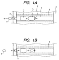
- Figs. 1A and 1B are plan views which illustrate the structure of a liquid flow path and plural heaters (Figs. 1A and 1B contain the case where the plural heaters are provided with different areas or different resistance respectively.)
- the liquid jet recording head used for the present invention which is one having multiple nozzles, a plurality of flow paths 1 are formed, each being separated by the flow path walls 6, and as means for generating energy for discharging liquid, a first heater (electrothermal converting member) 5 and a second heater 4 are provided in each of the flow paths. Then, by energizing either one of them or both of them, liquid in each of the flow paths is heated and discharged from plural discharge ports 3 arranged for each of the flow paths. The discharging liquid is supplied from a common liquid chamber 2 to each of the flow paths 1, and discharged from the corresponding discharge port 3. However, the first heater 5 and the second heater 4 are arranged in that order in the flow direction in flow path 1.
- the description will be made, at first, of the relationship between the creation of the bubble 7 by means of the heater 5 and the flow speed v of the liquid flow (or the atmospheric current when the meniscus 9 draws it) in the discharge port 3 that determines the speed V of the discharge liquid droplet 8.
- the multiple nozzle is adopted, which is formed by a plurality of nozzles as one body.
- plural discharge ports are represented for one liquid jet recording head.
- one heater 5 is used for the description herein, among those referred to in the preceding paragraph.
- the discharge ports positioned above are represented by the one shown in Fig. 1A, and those positioned below are represented by the one shown in Fig. 1B in order to make the operation easily understandable.
- Fig. 1A shows the state where a bubble is created by use of the discharge heater 5 and it is in the development.
- Fig. 1B shows the contracting process after the bubble has been developed to the maximum.
- the applied pulse current to the first heater is given as PI. Then, by this current, the first heater is heated.
- the bubbling volume is given as V B when the liquid is heated to bubble in the bubble generating area on the first heater 5.
- the flow speed at the discharge port 3 is given as v.
- the discharge direction is given as positive.
- the liquid flow path 1 direction is given as negative.
- the pulse current PI is applied to the first discharge heater. Then, after several ⁇ sec, the bubble 7 is created at time t 1 .
- the bubbling volume V B begins to be increased. At this juncture, the flow speed (here, liquid flow) becomes the one indicated by the v.
- the speed V of the discharged droplet 8 becomes the average of the positive components of the v, it is expressed as follows: Also, given the discharge port 3 as s 0 , the discharge amount Vd at this juncture is theoretically expressed as given below (that is, the area indicated by slanted lines is multiplied by S 0 ).
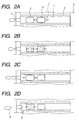
- Figs. 2A to 2D are views which illustrate the state where the first heater 5 and the second heater 4, which are arranged in the liquid flow path 1 of the liquid discharge head represented in Figs. 1A and 1B, are driven with different timing.
- the description will be made of the discharge ports positioned above and below in that order sequentially in accordance with Figs. 2A to 2D.
- Fig. 4 is a view which shows the flow speed at the time of driving each heater.
- the flow speed v of the first heater 5 is given as v 1
- the flow speed v of the second heater 4 is given as v 2.
- the average speed V is not made extremely large.
- the changing ratio of the average speed V is small even if the discharge amount is changed.
- the state of the discharge liquid droplet 8 is deformed in accordance with the average speed V. However, it becomes substantially a sphere due to the surface tension of the liquid during its flight.
- the droplet may be broken into plural pieces in some cases, but there occurs no problem as to the image to be formed on the surface of a recording medium if only the driving is made in condition that the droplet is arranged to form one dot.
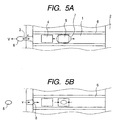
- Figs. 5A and 5B are plan views which illustrate the structure of the interior of the liquid flow path of a liquid recording head used in a first embodiment in accordance with the present invention.
- the recording head has the same structure as the liquid jet recording head shown in Figs. 1A and 1B and Figs. 2A to 2D.
- the areas of the first heater 5 and the second heater 4 are the same, and arranged in series in the direction of liquid flow in the liquid flow path 1. Therefore, the same reference marks as those used in Figs. 1A and 1B and Figs. 2A to 2D are also used for Figs. 5A and 5B.
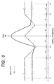
- Fig. 6 is a graph which schematically shows the discharge speed Vave and the discharge amount Vd of the discharge liquid discharged by the liquid jet recording head and the discharge method of the present invention.
- the axis of abscissa indicates the difference T between the driving timing of the first heater 5 and the second heater 4.
- the timing of the driving pulse application to the second heater 4 is defined as the positive side when the driving pulse is applied later. On the contrary, it is defined as the negative side when the driving pulse is applied to the second heater earlier than the timing difference 0.
- the driving pulse applied to the first heater 5 is given as a first pulse
- the driving pulse applied to the second heater 4 is given as a second pulse.
- the discharge amount is gradually decreased, and at the same time, the discharge speed is made slower significantly. This corresponds to the time 0 ⁇ t 2 ⁇ t 1 in Fig. 4.
- the discharge amount indicates its minimum value at a predetermined timing T 1 . Then, the discharge amount is gradually increased, and the discharge speed is substantially in a constant area b.
- the time T 1 at which the discharge amount indicates its minimum value is the timing that makes t 1 ⁇ t 2 in Fig. 4.
- the first liquid droplet which has been discharged by the first pulse, and the second liquid droplet which has been discharged by the second pulse are discharged in a continuous mode.
- This mode is preferable, because when these droplets are impacted on a recording medium, the dot configuration becomes substantially circular. If the timing of the driving pulse application is deviated larger still in the area b (T 1 to T 2 ), the discharge amount indicates its maximum value substantially at a predetermined timing difference T 2 . After that, even if the timing is largely deviated, the discharge amount is no longer increased, that is, the timing difference arrives at the area c (T 2 to T 3 ).
- the timing of the driving pulse application is deviated largely.
- the first and second liquid droplets are discharged in such a manner that the main portion of the second liquid droplet discharged by the second pulse is continuous to the trailing end of the first liquid droplet discharged by the first pulse or the first liquid droplet and second liquid droplet are discharged individuallly in succession.
- the dot configuration becomes almost circular in the area b, hence obtaining images in higher quality. Further, even if the first and second liquid droplets discharged separately in continuation, there is no problem as to the image formation if only the resultant impact positions are not greatly deviated on the surface of the recording medium when a liquid jet recording apparatus is structured and used as described later.
- the discharge amount In the area d (T 4 to 0), if the timing of the driving pulse application is made larger, the discharge amount is gradually decreased, and at the same time, the discharge speed is made slower significantly.
- the discharge amount indicates its minimum value at a predetermined timing difference T 4 . Then, the discharge amount is gradually increased, while the discharge speed arrives at the area e where it becomes substantially constant.
- the second liquid droplet which has been discharged by the second pulse, and the first liquid droplet which has been discharged by the first pulse are discharged in a continuous mode. If the timing of the driving pulse application is deviated larger still in the area e, the discharge amount indicates its maximum value substantially at a predetermined timing difference T 5 . After that, even if the timing is largely deviated, the discharge amount is no longer increased, that is, the timing difference arrives at the area f (T 5 to T 6 ).
- the main portion of the first liquid droplet discharged by the first pulse is discharged to the trailing portion of the second liquid droplet discharged by the second pulse in the continuous mode or the second and first liquid droplets are discharged separately in continuation.
- the heater which should be driven earlier can be driven faster to the extent that the timing is deviated.
- the gradation becomes richer, hence making it possible to obtain images printed in higher quality.
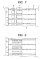
- Fig. 7 is a plan view which shows the structure of the interior of the liquid flow path of a liquid jet recording head used in a second embodiment of the present invention.
- the liquid flow path 1, the common liquid chamber 2, the discharge port 3, the second heater 4, the first heater 5, and the flow path walls 6 are the same as the liquid flow path 1, the common liquid chamber 2, the discharge port 3, the second heater 4, and the first heater 5, and the flow path walls 6 shown in Figs. 1A and 1B, and Figs. 5A and 5B.
- the areas of the first heater 5 and the second heater 4 used for the present embodiment are made 2 : 1. These heaters are arranged in series in the liquid flow path 1.
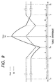
- Fig. 8 is a graph which schematically shows the discharge speed Vave and the discharge amount Vd of the liquid droplet discharged by the liquid jet recording head and the discharge method of the present invention.
- the standard of the time T represented on the axis of abscissa is defined as 0 when setting the timing of the driving pulse application to the first heater 5, and defined as the negative side when the timing of the driving pulse application to the second heater 4 is later than this time, and on the contrary, it is defined as the positive side when the driving pulse is applied to the second heater 4 earlier.
- the driving pulse applied to the first heater 5 is given as a first pulse
- the driving pulse applied to the second heater 4 is given as a second pulse.
- the discharge amount Vd and the discharge speed Vave of the liquid jet recording head do not present any axisymmetrical graph centering on the axis Y.
- the discharge amount Vd indicates its minimum value at a predetermined timing T 1 .
- the discharge amount Vd is gradually increased, and the discharge speed Vave is substantially in a constant area b.
- the first discharge liquid droplet which has been discharged by the first pulse, and the second discharge liquid droplet which has been discharged by the second pulse are discharged in a continuous mode.
- This mode is preferable, because when these droplets are impacted on a recording medium, the dot configuration becomes substantially circular.
- the discharge amount Vd indicates its maximum value substantially at a predetermined timing different T 2 . After that, the discharge amount is no longer increased even if the timing is deviated larger still, that is, it arrives at the area c.
- the timing of the driving pulse application is deviated largely.
- the first and second liquid droplets are discharged in such a manner that the main portion of the second liquid droplet discharged by the second pulse is continuous to the trailing end of the first liquid droplet discharged by the first pulse in the continuous mode or the first liquid droplet and second liquid droplet are discharged individually in succession.
- the bubbling power of the second heater 4 itself is smaller than that of the fi-rst heater 5 in accordance with the present embodiment.
- the second heater is positioned closer to the discharge port 3 than the first heater 5, the energy that forms the discharge liquid droplet is smaller than that of the first heater 5.
- the speed of formed discharge droplet is also smaller than the discharge liquid droplet formed by the first heater 5.
- the second discharge liquid droplet whose discharge speed is larger than the first discharge liquid droplet may catch up with the first discharge liquid droplet on the way even if the first discharge liquid droplet and the second discharge liquid droplet are discharged separately in continuation in the area c, provided that the distance between them comparatively closer to each other. Therefore, these droplets become one droplet before arriving at a recording medium.
- the discharge amount Vd is gradually decreased, and at the same time, the discharge speed Vave is made slower significantly.
- the discharge amount indicates its minimum value at a predetermined timing difference T 4 . Then, the discharge amount Vd is gradually increased, while the discharge speed Vave arrives at the area e where it becomes higher gradually.
- the second discharged droplet which has been discharged by the second pulse, and the first liquid droplet which has been discharged by the first pulse are discharged in a continuous mode.
- the first and second liquid droplets are discharged in such a manner that, the main portion of the first liquid droplet discharged by the first pulse is continuous to the trailing portion of the second liquid droplet discharged by the second pulse in the continuous mode or the second and first liquid droplets are discharged individually in succession.
- the discharge speed of the second discharge liquid droplet is higher than that of the first discharge liquid droplet.
- the discharge speed of the liquid droplets is greatly changed inevitably, and the impact positions of the discharge liquid droplets whose dot diameters are different are deviated eventually, causing the difficulty in improving the image quality.
- the discharge speed is extremely slow at the minimum discharge amount when the first heater 5 and the second heater 4 are driven individually.
- the discharge speeds do not change greatly even if the discharge amounts are modulated.
- the amount of droplets to be discharged and the speed thereof are different depending on the ratio of the heater areas, and the sizes thereof as indicated by the fact that the relationship between the discharge speeds and the discharge amounts becomes different.
- the size, configuration, and arrangement of each of the heaters are fixed. Therefore, by making the above-mentioned driving pulses different, it becomes possible to apply those shown in the first embodiment to the operation of the second embodiment, and vice versa. Then, the arrangement may be made so that the configuration of driving pulse applied to each of the heaters is made changeable per heater.
- the timing of the second pulse application it is desirable to apply the second pulse during the period when the meniscus, which is formed on the discharge port by the first liquid droplet discharged by the first pulse, resides on the heater side rather than on the discharge port surface side. This is because the amount of droplet discharged by the creation of bubble becomes greater when the distance between the bubble and the meniscus is shorter. With the timing being set as this, the performance of discharges becomes more effective.
- nozzle PI used for ink discharges is shown.
- This nozzle is used for a third embodiment in accordance with the present invention.
- a smaller front side heater 102 on the nozzle opening edge 101a side, and a larger rear side heater 103 on the location behind the smaller one.
- the smaller heater 102 is driven at first.
- the larger heater 103 is driven by means of the driving circuit (not shown).
- the driving timing of both heaters 102 and 103 is set preferably at equal to or more than 15 ⁇ s with intervals of 15 to 30 ⁇ s. As to this driving timing, the description will be made later.
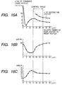
- the applicant hereof has measured the discharge speed v, the ink discharge amount Vd, and the driving frequency fr when the driving timing is made changeable for both heaters 102 and 103 variously.
- the result is shown in Figs. 16A to 16C.
- the second ink droplet is indicated by dotted line, which shows the discharge condition where the first ink droplet is not separated from the second ink droplet.
- the discharge speed v and the driving frequency fr are comparatively high, and the fluctuation width is smaller. Therefore, by setting the timing arbitrarily within this range, it becomes possible to change the ink discharge amounts Vd without varying the discharge speed v and the driving frequency fr too much, that is, without affecting the print quality greatly. It is effective that the ink discharge amounts Vd should be changed within the interval range of approximately 30 ⁇ s or less. In this range, the discharge amounts are made changeable considerably. On the other hand, in the range of interval being 0 ⁇ s (both heaters 102 and 103 are energized at the same time) to approximately 15 ⁇ s, the fluctuation of the discharge speed v and the driving frequency is large. Therefore, the result is almost the same as the conventional example.
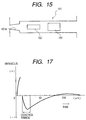
- Fig. 17 is a graph which shows the elapsed time since the front side heater has been driven, and the fluctuation of the ink meniscus on the nozzle opening edge.
- Fig. 17 shows the result of the observation of the state until the vibration of meniscus is attenuated while the driving of the rear side is at rest.
- the positive side of the meniscus is the amount thereof that expands externally from the discharge port edge, while the negative side is the amount thereof that retracts to the inner side of the discharge port edge portion.
- the meniscus means the stabilization point of the gas liquid interface in the discharge port portion. Since the stabilization point is the tip of the ink liquid column immediately after ink has been discharged (0 to 10 ⁇ s), this point is adopted and represented as such interface for the convenience' sake. As a result, the meniscus is positioned on the positive side immediately after the ink discharge. After that, as the bubble is being contracted, the liquid column is constricted in the vicinity of the discharge port. Then, one other stabilization point is created at the constricted position. This portion is defined as the meniscus. Here, around 10 to 15 ⁇ s range in Fig. 17, a discontinued portion takes place. In other words, for the present invention, the timing at the position where the meniscus has been retracted from the discharge port edge is substantially equal to the timing at which the constriction occurs in the column of the discharged liquid near the discharge port.
- the present embodiment produces its effect when the timing difference is 15 ⁇ s or more.
- this effective range lies during the period when the meniscus is on the negative side, that is, when the heater on the rear side is driven, while the meniscus resides on the retracted position from the nozzle opening edge.
- Fig. 17 shows that the meniscus is on the positive side at the timing of 80 ⁇ s or more.
- the discharge amount does not change noticeably at the timing of 30 ⁇ s or more, not to mention the range of 80 ⁇ s or more, where no essential effect is obtainable as described earlier.
- the reasons why the discharge amount varies depending upon the driving timing of the heater are as given below.
- the meniscus when the meniscus is caused to retract following the contraction of the bubble which has been developed by the driving of the front heater, the rear heater is driven to perform bubbling. Then, the discharge force of such bubbling is offset by the retracting speed of the meniscus, which makes the discharge amount smaller. If the timing is made slower, the retracting speed of the meniscus is attenuated, thus enabling the discharge amount to increase. After that, the discharge amount is increased more when the meniscus is restored. Here, the changing amount becomes moderate.
- the flow resistance in accordance with the present embodiment, when the bubble, which has been developed by the earlier driving of the heater on the front side, is contracted, the flow resistance (inertance) is smaller in front of the heater than the flow resistance in back of the heater when the rear side heater is driven. As a result, the meniscus is retracted greatly. Then, by driving the rear heater when the meniscus is retracted and restored, it becomes possible to modulate the ink discharge amount considerably. Essentially, it is effective to drive the rear heater during the period when the meniscus resides on the retracted position from the nozzle opening edge.
- the formation step is set, by the application of the present embodiment, at the timing of approximately 15 ⁇ s in order to produce pixel having a smaller ink discharge amount, while the formation step is set at the timing of approximately 15 ⁇ s to produce pixel having a larger ink discharge amount in response to the recording signals, for example, it becomes possible to perform the gradational recording effectuated by the larger and smaller dots in accordance with the recording signals, thus providing stabilization for the print quality without changing the discharge speeds and frequencies considerably in both steps. With the timing being made more multiple, it becomes possible to perform a multi-gradational recording in good condition.
- timing With the timing being set at approximately 15 ⁇ s, it may be possible to record at comparatively higher speed with a smaller amount of ink discharge.
- the larger heater on the rear side is driven earlier than the smaller heater on the front side, it is possible to obtain a larger discharge amount Vd without making the discharge speed v too fast.
- Fig. 19 is a view which shows the nozzle 101 used in another embodiment.
- the front side heater 102 and the rear side heater 103 which are configured to be long and narrow, are arranged shiftingly.
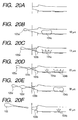
- Figs. 20A to 20F are views which schematically illustrate each state of ink and bubble in the nozzle 101 as the time elapses.
- Figs. 20A to 20F there are indicated the elapsed time since the start of driving the front side heater 102 in each of the events, respectively.
- Fig. 20A shows the state before heaters are driven, and when the front side heater 102 is driven, film boiling takes place in ink to create a bubble 104a. By the bubbling pressure exerted by this bubble 104a, ink discharge begins at the discharge port (see Fig. 20B).
- the constriction occurs on the ink liquid column at the discharge port portion. Then the meniscus is formed.
- the ink droplet 105 which is being discharged from the nozzle, advances forward without any retraction (at this point, the volume of the ink droplet 105 is approximately 10 pl and the discharge speed is approximately 7 m/s). Any other ink than this droplet is drawn in from the discharge port along the contraction of the bubble 104a due to the bubbling pressure thereof. Thus, the meniscus 105b is retracted from the nozzle opening portion 101a.
- the rear side heater 103 is driven.
- a bubble 104b is created with heating given by the heater 103 (see Fig. 20D).
- the contraction of the bubble 104a and the expansion of the bubble 104b make progress simultaneously.
- the ink suction due to the contraction of the bubble created on the front side is offset by the expansion of the bubble 104b which has been created on the rear side.
- the expansion of the bubble 104b functions not only to offset the contraction of the bubble 104a, but also, enable the meniscus 105b to advance again.
- the second liquid droplet portion 105c is formed on the trailing end of the first liquid droplet portion 105a of the ink droplet 105.
- the larger diameter portion of the ink droplet formed by the driving of the front side heater 102 is indicated as the first liquid droplet portion 105a, and the larger diameter portion of the ink droplet formed by the rear side heater 103 as the second liquid droplet portion 105c.
- the second liquid droplet portion 105c is formed before the tail section of the first liquid droplet portion 105a is cut off in the nozzle 101. Therefore, the ink droplet 105 becomes the one having the larger diameter portion like a knot in two locations thereof.
- the bubble 104a is made extinct, while the bubble 104b is continuously expanded. Then, the ink droplet 105 further advances (see Fig. 20E).
- the bubble 104b is contracted after having expanded, the ink droplet 105 is cut off from ink in the nozzle 101, and the meniscus 105b is retracted (see Fig. 20F). Since the second liquid droplet portion 105c is created in the state where the meniscus 105b has comparatively retracted, and its advancing speed is fast. Therefore, it catches up with the first liquid droplet portion 105a in the ink droplet 105.
- the ultimate discharge amount of the ink droplet 105 is approximately 30 pl, and the discharge speed is approximately 8 m/s.
- Figs. 21A to 21F there are indicated the elapsed time since the start of driving the front side heater 102 in each of the events, respectively.
- Fig. 21A shows the state before heaters are driven, and when the front side heater 102 is driven, film boiling takes place in ink to create a bubble 106a. Then, as in the third embodiment, the bubble 106 is gradually expanded to begin the ink discharge (see Fig. 21B). After that, when the expansion of the bubble by the front heater 102 is settled, and the contraction of the bubble 106a begins (see Fig. 21C).
- the ink droplet (a first ink droplet) 107a is discharged from the nozzle. Ink remaining in the nozzle is drawn in along the contraction of the bubble 106a. The meniscus 107b is retracted from the nozzle opening edge 101a.
- the rear side heater 103 is driven to create a bubble 106b with heating given by the rear side heater 103 (see Fig. 21D).
- the bubble 106a is extinct.
- the rear side heater 103 is larger and the action thereof is greater, and as the expansion of the bubble 106b advances, the meniscus 107b makes progress forward again.
- the second ink droplet 107c is discharged behind the first ink droplet 107a.
- the speed of the second ink droplet 107c is approximately 9 m/s as clear from Fig. 16A, which is faster than the speed of the first ink droplet 107a. Therefore, the second ink droplet catches up with the first ink droplet so that both ink droplets 107a and 107c are combined (are made one body) (see Fig. 21E).
- the bubble 106a is contracted and made extinct soon. Along with this extinction, the meniscus 108 is retracted. At this juncture, the combined ink droplet 107 flies substantially at the same speed as the first ink droplet 107a (see Fig. 21F).
- the amount of meniscus 107b which is retracted after the completion of the ink discharge as described above, may exert influence on the next ink discharge.
- this retracting amount of meniscus is determined by the balance between the inertance (flow path resistance) on the front side and the inertance on the rear side of the heater in use when the disappearing takes place on the rear side heater. Therefore, if the front side inertance (flow resistance) is greater as in the present embodiment, the retracting amount of the meniscus becomes smaller. Then, the printing frequency is enhanced.
- Fig. 22 is a view which shows a nozzle 101 used for ink discharges in accordance with this comparative example.
- nozzle 101 there are arranged a narrower front side heater 102 on the nozzle opening edge side 101a, and a wider rear side heater 103 on the location behind it.
- the front side heater 102 is, at first, driven by a driving circuit (head driver), which will be described later, when printing signals are received. Then, after that, the rear side heater 103 is driven.
- the driving timing for both heaters 102 and 103 is set in a range of 10 to 15 ⁇ s or preferably, in a range of 11 to 14 ⁇ s approximately.
- a single voltage pulse of 4 ⁇ s wide should be applied at intervals of 12 ⁇ s approximately. Now, the description will be made of this driving timing.
- the applicant hereof has measured the ink discharge speed v, the discharge amount Vd, and the refilling frequency fr with the driving timing of both heaters 102 and 103 being made changeable. Further, the voluminal changes of bubble after bubbling is observed with the results indicated in Figs. 23A to 23D.
- the delay timing (interval) of the heater 103 which is driven later than the heater 102 which has been driven earlier is in a range of 10 to 15 ⁇ s, particularly in the range of 12 ⁇ s
- the discharge speed v is comparatively large (approximately 8 m/s)
- the refilling frequency is substantially at the maximum value (13.5 to 13.8 kHz approximately)
- the ink discharge amount vd is kept substantially at the minimum value (10 pl). Therefore, if the timing is set within this range, it becomes possible to form fine dots, each with a smaller amount of ink at a higher discharge speed, and a higher refilling frequency as well.
- the ink discharge amount Vd is larger (approximately 40 pl), and the frequency fr is extremely lower (approximately 10 kHz), although the discharge speed v is faster (approximately 12 m/s).
- the retracting amount of the meniscus becomes greater after discharge, which necessitates an extra time for refilling. Therefore, a longer interval of the ink discharges should be provided so as not to perform any higher printing.
- the discharge speed v and the frequency fr are made lower and any significant effect is not anticipated any longer, although the ink discharge amount Vd is gradually made smaller.
- the timing exceeds 15 ⁇ s, the discharge amount Vd becomes greater abruptly, while the frequency fr is made lower. Therefore, any higher printing cannot be attained, either.
- the discharge amount is 10 pl
- the discharge speed is 6 m/s
- the refilling frequency is 10 kHz, approximately.
- the discharge amount is 30 pl
- the discharge speed is 10 m/s
- the refilling frequency is 14 kHz, approximately. From these findings, the discharge speed of approximately 8 m/s with the delayed driving by approximately 12 ⁇ s is faster than that of the driving only by the front side heater 102.
- the larger size of the rear side heater 103 contributes to the presentation of this faster speed.
- Fig. 23D shows the voluminal ratio between the development and contraction of the bubble after the creation of the bubble and on subsequent to the front side heater 102 having been driven.
- the heater here, the front side heater 102
- the heater is driven to create a bubble for discharging ink.
- the contraction and disappearing of the previous bubble is offset by the creation and development of the later bubble.
- the later bubble is developed. In this manner, the total volume of bubbles is kept constant in a certain period of time. During such period, ink scarcely flows. Consequently, the retraction of the meniscus, which is cased by the ink being drawn into the interior of the nozzle, is made smaller.
- the function of the driving method may be defined as the adjustment of a refilling frequency to the one that may be obtainable when only the post-driving heater is driven.
- the meniscus controlled by means of the post-driving heater functions to govern the refilling frequency of this method.
- the ink droplet is discharged at faster discharge speed when the front side heater 102 is driven, because the inertance (flow path resistance) of the front side heater 102 is smaller in front of it, while the inertance is larger in back of it. As a result, the inverted flow of ink toward the rear side can hardly take place. Also, the inertance in front of the rear side heater 103 is larger, while the inertance in back of it is smaller. Therefore, when the bubble created by the driving of the rear side heater 103 is contracted to disappear, ink on the rear side is drawn more than that on the front side.
- Fig. 24 shows the nozzle in accordance with another comparative example.
- This nozzle 101 is provided with a smaller front side heater 102 and a larger rear side heater 103, which are arranged in series on the front and back sides, respectively.
- the obtainable effect is the same as in the case represented in Fig. 22.
- Fig. 25 shows the nozzle in accordance with still another comparative example.
- the front side heater 102 and the rear side heater 103 in the same configuration, but these heaters are partly deviated in its arrangement. In this case, the discharge speed v does not change so greatly as in the case represented in Fig. 22.
- the driving pulses may be not only the single pulse as described above, but may be double pulse, or may be the complex pulse formed by them together.
- each of the heaters shown in Fig. 22, Fig. 24, and Fig. 25 can be driven individually. It is preferable to unify the bubbling initiation voltage so that any one of them can be driven by the application of one and the same driving voltage. For that matter, the length of each heater is made substantially equal.
- the front side heater (nearer to the discharge port) is made smaller than the one on the rear side (father away from the discharge port) or it is preferable to make them substantially the same.
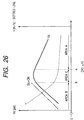
- Fig. 26 is a graph which shows the relationship between the ink discharge amount Vd and the discharge speed v with respect to the distance OH from the discharge port of the heater when one heater is driven independently, and which also shows the product of the area So of the discharge port and the distance OH together.
- the singular points a and b are regulated, and the distance OH is divided into three areas: the area equal to or more than a is designated as A; the area equal to or less than b, as B; and the area between a and b, C.
- the characteristic tendency of each area is: in the area S, the discharge speed v and the discharge amount Vd are substantially proportional as the distance OH is increased, and the v / Vd is almost constant; in the area B, the discharge amount Vd is almost proportional to the product of the discharge area So and the distance OH, and the discharge speed v is inversely proportional. Then, the v / Vd is reduced as the distance OH is increased; and in the area C, the discharge amount Vd is almost constant.
- each of the above areas may be defined as given below with attention given to each of the discharge amounts Vd and the discharge speeds v, respectively.
- the discharge speed v is made along with the increase of the distance OH. Particularly, in the area C, its changing amount becomes moderate.
- the heater positions it is preferable to position the front side heater in the area B. Then, it becomes possible to discharge finer droplets at higher speeds.
- Figs. 27A to 27F are views which schematically illustrate each state of ink and bubble in the nozzle 101 of the present comparative example as the time elapses.
- Figs. 27A to 27F there are indicated the elapsed time since the start of driving the front side heater 102 in each of the events, respectively.
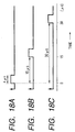
- Fig. 28 shows the driving pulse A of the front side heater 102, and the driving pulse B of the rear side heater 103 as well.
- the rear side heater 103 is driven. After that, when the development of the bubble by means of the front side heater 102 is settled, and the contraction of the bubble 104a begins, a bubble 104b which has been developed with heating by the rear side heater 103 is increase at the same time (see Fig. 27C). At this juncture, the ink droplet 105, which is being discharged from the nozzle 101, advances forward without any retraction. The bubble 104a has already begun to be contracted, and the force that draws in the surrounding ink is activated.
- the bubble 104b is contracted to disappear, thus acting upon the surrounding ink to be drawn in.
- the ink suction force exerted by the contraction and disappearing of the bubble 104b acts upon the rear portion of the nozzle rather than the front portion thereof.
- the ink suction force exerted by the contraction and disappearing of the bubble 104b has the promotional effect on the refilling (ink refilling) rather than on the retraction of the meniscus. In this manner, the refilling frequency is enhanced to make higher printing possible.
- the front and rear inertances of the rear side heater 103 maintain the relationship as described earlier. Therefore, the bubbling created by the rear side heater 103 does not contribute excessively to the ink discharge from the nozzle opening end directly.
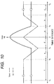
- Fig. 9 is a view which shows a liquid discharge head used in a fifth embodiment in accordance with the present invention.
- the liquid discharge head is provided with a plurality of heaters in the nozzles, respectively, which are arranged in parallel with the flow path direction at the same position (the distance OH from the edge of the heater on the discharge port side to the discharge port is equal to each of them), each having the same configuration, resistance, and area, respectively.
- Fig. 10 is a graph which shows the relationship between the discharge speed Vave and the discharge volume Vd, which are obtained by deviating timing of these heaters altogether. The graph is the same as a whole as the one described in conjunction with Fig. 8. As readily understandable from Fig. 9 and Fig.
- Fig. 11 is an exploded perspective view which schematically shows the liquid discharge head cartridge.
- this liquid discharge head cartridge is mainly formed by a liquid discharge head unit 200 and a liquid container 580.
- the liquid discharge head unit 200 comprises an elemental substrate 501, separation walls 530, a grooved member 550, a pressure spring 578, a liquid supply member 590, and a supporting member 570, among some others.
- an elemental substrate 501 On the elemental substrate 501, a plurality of heat generating resistors are arranged in lines, and also, a plurality of functional devices are arranged in order to drive these heat generating resistors selectively.
- This elemental substrate 501 and the grooved ceiling 550 are bonded to form discharge flow paths (not shown) for distributing discharge liquid to be discharged.
- the pressure spring member 578 provides the grooved member 550 with biasing force acting in the direction toward the elemental substrate 501. With this biasing force, the elemental substrate 501, the grooved member 550, as well as the supporting member 570 which will be described later, are integrally formed together in good condition.
- the supporting member 570 supports the elemental substrate 501 and others. On this supporting member 570, there are further provided a circuit board 571 connected with the elemental substrate 501 to supply electric signals, and a contact pad 572 which is connected with the apparatus side to exchange electric signals with the apparatus side.
- the liquid container 590 retains in it discharge liquid such as ink.
- the positioning unit 594 is provided for the arrangement of a connecting member that connects the liquid discharge head and the liquid container, and the fixing shafts 595 is provided for fixing such connecting member.
- the discharge liquid is supplied to the liquid supply path 581 of the liquid supply member 580 from the liquid supply path 592 of the liquid container through the supply path 584 of the connecting member, and then, supplied to the common liquid chamber by way of the discharge liquid supply paths 583, 571, and 521 arranged for each of the members.
- the arrangement may be made to use it by refilling liquids after each of them has been consumed.
- Fig. 12 is a view which schematically shows the structure of a liquid discharge apparatus having mounted on it a liquid discharge head described earlier.
- a carriage HC of the liquid discharge apparatus mounts on it a detachable head cartridge structured by a liquid tank unit 90 that retains ink and a liquid discharge head unit 200.
- the carriage reciprocates in the width direction of a recording medium 150, such as a recording paper sheet, which is carried by means for carrying a recording medium.
- driving signals are supplied to the liquid discharge head unit on the carriage from driving signal supply means (not shown), recording liquid is discharged from the liquid discharge head to the recording medium in accordance with the driving signals.
- the liquid jet recording apparatus of the present embodiment is provided with a motor 111 that servers as a driving source, gears 112 and 113, a carriage shaft 115, and others that are needed for transmitting the power from the driving source to the carriage.
- a motor 111 that servers as a driving source
- gears 112 and 113 that are needed for transmitting the power from the driving source to the carriage.
- Fig. 13 is a block diagram which shows the entire body of the recording apparatus that performs ink jet recording with the application of the liquid discharge method and the liquid discharge head used for the present invention.
- This recording apparatus receives printing information from a host computer 300 as control signals.
- the printing information is provisionally held on the input interface 301 arranged in the interior of the recording apparatus.
- the printing information is converted to the data executable by the recording apparatus, and inputted into the CPU 302 which dually serves as means for supplying head driving signals.
- the CPU 302 processes the data inputted to the CPU 302 using the RAM 304 and other peripheral units, thus converting them into the data to be printed (image data).
- the CPU 302 produces the motor driving data to drive the driving motor to move the recording sheet and the recording head in synchronism with the image data thus produced.
- the image data and motor driving data are transmitted to the head 200 and the driving motor 306 through the head driver 307 and the motor driver 305, respectively. Then, with the controlled timing, the head and motor are driven so that images are formed.
- the recording media which are usable by a recording apparatus of the kind for the provision of ink or other liquids thereon, there may be named various kinds of paper and OHP sheets, plastic material usable for compact disc, ornamental board, or the like, textiles, metallic materials such as aluminum, copper, leather material such as cowhide, hog hide, or artificial leather, wood material such as wood or plywood, bamboo material, ceramic material such as tiles, or three-dimensional structure such as sponge.
- a printing apparatus that records on various paper and OHP sheets
- a recording apparatus for use of recording on compact discs and other plastic materials a recording apparatus for use of recording on metal, such as a metallic plate
- a recording apparatus for use of recording on leathers a recording apparatus for use of recording on woods
- a recording apparatus for use of recording on ceramics a recording apparatus for use of recording on a three-dimensional netting structure, such as sponge.
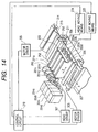
- Fig. 14 is a view which schematically illustrates the structure of the ink jet recording system using the liquid discharge head 201 used for the present invention.
- the liquid discharge head is a full line type head where a plurality of discharge ports are arranged at intervals of 360 dpi in a length corresponding to the recordable width of the recording medium 150.
- Four liquid discharge heads, each one of them for use of yellow (Y), magenta (M), cyan (C), and black (Bk) color, are fixed and supported by a holder 202 in parallel with each other at given intervals in the direction X.
- each of the liquid discharge heads is driven.
- each of the liquid discharge heads four color ink of Y, M, C and Bk are supplied from each of the ink containers 204a to 204d.
- each of the head caps 203a to 203d having in it a sponge or some other ink absorbent, respectively.
- each of the liquid discharge heads is covered with each of the head caps in order to keep them in good condition.
- a reference numeral 206 designates a carrier belt which constitutes carrier means for carrying various kinds of recording media as described earlier for each of the embodiments.
- the carrier belt 206 is drawn around a given path by means of various rollers, and driven by driving rollers connected with a motor driver 305.
- the head is not necessarily limited to the full line type. It may be possible to adopt a smaller liquid discharge head which is arranged to be in a mode that recording is performed by carrying such head in the width direction of a recording medium.
- the present invention is particularly effective when applied to ink jet heads and recording apparatus which utilize thermal energy.
- discharge signals are supplied from a driving circuit to electrothermal converting members disposed on a liquid (ink) retaining sheet or liquid path, and in accordance with recording information, at least one driving signal is given in order to provide recording liquid (ink) with a rapid temperature rise so that film boiling, which is beyond nuclear boiling, is created in the liquid, thus generating thermal energy that creates film boiling on the thermoactive surface of the recording head.
- a bubble is formed in liquid (ink) by this driving signal one to one.
- This method is, therefore, particularly effective for the on-demand type recording method.
- the liquid (ink) is discharged from each of the discharge ports to produce at least one droplet.
- the driving signal is more preferably in the form of pulses because the development and contraction of the bubble can be effectuated instantaneously and appropriately.
- the liquid (ink) is discharged with quicker response.
- the driving signal in the form of pulses is preferably such as disclosed in the specifications of U.S. Patent Nos. 4,463,359 and 4,345,262.
- the temperature increasing rate of the thermoactive surface is preferably such as disclosed in the specification of U.S. Patent No. 4,313,124 for an excellent recording in a better condition.
- the structure of the recording head may be as shown in each of the above-mentioned specifications wherein the structure is arranged to combine the discharging openings, liquid paths, and the electrothermal converting members (linear type liquid paths or right-angled liquid paths), as well as may be such structure as disclosed in the specifications of U.S. Patent Nos. 4,558,333 and 4,459,600 in which the thermal activation portions are arranged in a curved area. All of these structures are suitable for use by the present invention. In addition, the present invention is effectively applicable to the structure disclosed in Japanese Patent Laid-Open Application No.
- recording apparatus for the use of the present invention, it may be possible to adopt a copying apparatus combined with a reader, in addition to the image output terminal for a computer or other information processing apparatus. Also, it may be possible to adopt facsimile equipment provided with transmitting and receiving functions, among some others.
- a plurality of electrothermal converting members thus provided is driven one after another to make the discharge amount changeable with substantially constant discharge speeds of droplets for the respective difference of driving timing in a driving condition within a range which enables the amount of droplets to change. Then, it becomes possible to change discharge amount, while maintaining the flying speeds of ink droplets substantially constant when arriving at the surface of a recording medium. In this way, high quality prints can be obtained without deviation of impact positions irrespective of the dot diameters, larger or smaller.
Claims (20)
- Verfahren zum Ausstoßen von Flüssigkeit aus einer Düse mit wenigstens einem ersten elektrothermischen Element (5, 103) und einem zweiten elektrothermischen Element (4, 102), die beide in der Lage sind, eine Blase zum Ausstoß von Flüssigkeit aus der Düse zu bilden, mit den Verfahrensschritten:dadurch gekennzeichnet, daßAnsteuern des ersten elektrothermischen Elements mit einem ersten elektrischen Impuls, um eine erste Blase zu erzeugen;Ansteuern des zweiten elektrothermischen Elements mit einem zweiten elektrischen Impuls, um eine zweite Blase zu bilden, Initialisieren des zweiten elektrischen Impulses, der von der Initialisierung des ersten elektrischen Impulses um eine Zeitverschiebung versetzt ist, die ausgewählt ist zum Erzielen des Ausstoßes eines vorbestimmten Flüssigkeitsvolumens durch die Kombinationswirkung der Expansion der ersten und der zweiten Blase,
die Zeitverschiebung in einem Bereich (T1:T2; T4:T5) zwangsweise festgelegt ist, in dem die Geschwindigkeit der ausgestoßenen Flüssigkeit im wesentlichen unabhängig vom Betrag der Zeitverschiebung ist. - Verfahren nach Anspruch 1, bei dem wenigstens ein Teil des zweiten elektrothermischen Elements (4, 102) näher an der Düse liegt als irgend ein Teil des ersten elektrischen Elements (5, 103).
- Verfahren nach Anspruch 1 oder 2, bei dem sich wenigstens ein Teil des zweiten elektrothermischen Elements (4, 102) im selben Abstand von der Düse befindet, wie dies beim letzten Teil des ersten elektrothermischen Elements (5, 103) der Fall ist.
- Verfahren nach einem der Ansprüche 1 bis 3, bei dem der erste Impuls gegenüber dem zweiten Impuls verzögert ist.
- Verfahren nach einem der Ansprüche 1 bis 3, bei dem der zweite Impuls gegenüber dem ersten Impuls verzögert ist.
- Verfahren nach einem der Ansprüche 1 bis 5, bei dem das zweite elektrothermische Element (4, 102) kleinflächiger als das erste elektrothermische Element (5, 103) ist.
- Verfahren nach einem der Ansprüche 1 bis 5, bei dem die Flächen vom ersten und zweiten elektrischen Element dieselben sind.
- Verfahren nach einem der Ansprüche 1 bis 7, bei dem das Ausstoßen der Flüssigkeit mit zwei oder mehr individuellen Tröpfchen aus der Düse erfolgt, deren Geschwindigkeit so eingerichtet ist, daß später ausgestoßene Tröpfchen früher ausgestoßene Tröpfchen erreichen und mit diesen kollidieren, so daß die insgesamt ausgestoßene Flüssigkeit die Oberfläche des Aufzeichnungsmediums in Form eines Tröpfchens beaufschlagt.
- Verfahren nach einem der Ansprüche 1 bis 7, bei dem vor der Trennung des aus der Düse zurückziehenden Meniskus ein elektrischer Impuls das andere Element vom ersten oder zweiten elektrothermischen Element beaufschlagt, wenn ein Flüssigkeitsausstoß folgt, den entweder das erste oder zweite elektrothermischen Element herbeiführt.
- Verfahren nach einem der Ansprüche 1 bis 9, bei dem die ausgestoßene Flüssigkeit die Aufzeichnung auf einem Aufzeichnungsmedium gemäß einem von außen gelieferten Auszeichnungssignal herbeiführt und bei dem jeder Punkt auf der Oberfläche des Aufzeichnungsmediums durch Auftreffen eines einzelnen Tropfens entsteht.
- Verfahren nach Anspruch 10, das die Zeitverschiebung gemäß der im Aufzeichnungssignal enthaltenen Gradationsinformation auswählt, wobei die Information die Tintenmenge vorschreibt, die bei jedem Punkt aufzutragen ist.
- Vorrichtung zum Ausstoßen von Flüssigkeit aus einer Düse mit wenigstens einem ersten elektrothermischen Element (5, 103) und einem zweiten elektrothermischen Element (4, 102), die beide in der Lage sind, eine Blase zum Ausstoß von Flüssigkeit aus der Düse zu bilden, mit:dadurch gekennzeichnet, daßeinem ersten Ansteuermittel, das einen ersten elektrischen Impuls an das erste elektrothermische Element liefert, um eine erste Blase zu bilden;einem zweiten Ansteuermittel, das einen zweiten elektrischen Impuls an das zweite elektrothermische Element liefert, um eine zweite Blase zu erzeugen, mit Initialisieren des zweiten elektrischen Impulses, der gegenüber der Initialisierung des ersten elektrischen Impulses um eine Zeitverschiebung versetzt ist, die ausgewählt ist zum Erzielen des Ausstoßes eines vorbestimmten Flüssigkeitsvolumens durch die Kombinationswirkung der Expansion der ersten und der zweiten Blase,
die Zeitverschiebung in einem Bereich (T1:T2; T4:T5) zwangsweise festgelegt ist, in dem die Geschwindigkeit der ausgestoßenen Flüssigkeit im wesentlichen unabhängig vom Betrag der Zeitverschiebung ist. - Vorrichtung nach Anspruch 12, bei der sich wenigstens ein Teil des zweiten elektrothermischen Elements (4, 102) näher an der Düse befindet als irgend ein anderer Teil des ersten elektrothermischen Elements (5, 103).
- Vorrichtung nach Anspruch 12 oder 13, bei der wenigstens ein Teil des zweiten elektrothermischen Elements (4, 102) im selben Abstand von der Düse befindet, wie dies beim letzten Teil des ersten elektrothermischen Elements (5, 103) der Fall ist.
- Vorrichtung nach einem der Ansprüche 12 bis 14, bei der das erste und zweite Ansteuermittel so eingerichtet ist, daß der erste Impuls gegenüber dem zweiten Impuls verzögert ist.
- Vorrichtung nach einem der Ansprüche 12 bis 14, bei der das erste und zweite Ansteuermittel so eingerichtet ist, daß der zweite Impuls gegenüber dem ersten Impuls verzögert ist.
- Vorrichtung nach einem der Ansprüche 12 bis 16, bei der das zweite elektrothermische Element (4, 102) kleinflächiger als das erste elektrothermische Element (5, 103) ist.
- Vorrichtung nach einem der Ansprüche 12 bis 16, bei der Flächen vom ersten und zweiten elektrischen Element dieselben sind.
- Vorrichtung nach einem der Ansprüche 12 bis 18, bei der das erste und zweite Ansteuermittel eingerichtet ist zum Ausstoß von Flüssigkeit, um eine Aufzeichnung auf einem Aufzeichnungsmedium gemäß einem extern angelegten Signal herbeizuführen, wobei jeder Punkt auf der Oberfläche des Aufzeichnungsmediums durch Auftreffen eines einzelnen Tropfens entsteht.
- Vorrichtung nach einem der Ansprüche 12 bis 18, die die Zeitverschiebung gemäß im Aufzeichnungssignal enthaltenen Gradationsinformationen auswählt, die die aufzutragende Tintenmenge bei jedem Punkt vorschreiben.
Applications Claiming Priority (9)
| Application Number | Priority Date | Filing Date | Title |
|---|---|---|---|
| JP206549/97 | 1997-07-31 | ||
| JP20654997 | 1997-07-31 | ||
| JP20654997A JPH1148481A (ja) | 1997-07-31 | 1997-07-31 | 液体吐出記録ヘッドにおける液体吐出方法、液体吐出記録装置における吐出方法 |
| JP25353297A JP3809261B2 (ja) | 1997-09-18 | 1997-09-18 | インクジェット記録方法およびインクジェット記録装置 |
| JP25353297 | 1997-09-18 | ||
| JP253532/97 | 1997-09-18 | ||
| JP26234697 | 1997-09-26 | ||
| JP26234697A JP4289692B2 (ja) | 1997-09-26 | 1997-09-26 | インクジェット記録方法およびインクジェット記録装置 |
| JP262346/97 | 1997-09-26 |
Publications (3)
| Publication Number | Publication Date |
|---|---|
| EP0894625A2 EP0894625A2 (de) | 1999-02-03 |
| EP0894625A3 EP0894625A3 (de) | 2000-08-23 |
| EP0894625B1 true EP0894625B1 (de) | 2004-11-10 |
Family
ID=27328648
Family Applications (1)
| Application Number | Title | Priority Date | Filing Date |
|---|---|---|---|
| EP98306089A Expired - Lifetime EP0894625B1 (de) | 1997-07-31 | 1998-07-30 | Verfahren und Vorrichtng zum Ausstossen von Flüssigkeit |
Country Status (7)
| Country | Link |
|---|---|
| US (1) | US6375309B1 (de) |
| EP (1) | EP0894625B1 (de) |
| CN (1) | CN1091686C (de) |
| AU (1) | AU7868798A (de) |
| CA (1) | CA2244490C (de) |
| DE (1) | DE69827438T2 (de) |
| ES (1) | ES2227781T3 (de) |
Families Citing this family (12)
| Publication number | Priority date | Publication date | Assignee | Title |
|---|---|---|---|---|
| JP3311284B2 (ja) | 1997-10-24 | 2002-08-05 | キヤノン株式会社 | 液体吐出記録ヘッド、液体吐出記録方法および液体吐出記録装置 |
| CA2318983C (en) * | 1998-01-23 | 2005-12-20 | Microinjector, Llc | Apparatus and method for using bubble as virtual valve in microinjector to eject fluid |
| US6854820B2 (en) | 2001-09-26 | 2005-02-15 | Canon Kabushiki Kaisha | Method for ejecting liquid, liquid ejection head and image-forming apparatus using the same |
| JP3617644B2 (ja) * | 2002-03-26 | 2005-02-09 | ソニー株式会社 | 液体吐出装置 |
| CN100586717C (zh) * | 2003-09-03 | 2010-02-03 | 索尼株式会社 | 液体排出装置和液体排出方法 |
| US7219970B2 (en) | 2003-10-14 | 2007-05-22 | Hewlett-Packard Development Company, L.P. | Method and a system for single ligament fluid dispensing |
| JP4213195B2 (ja) * | 2005-08-09 | 2009-01-21 | 富士通株式会社 | 遅延時間解析装置、制御方法及びプログラム |
| US8226217B2 (en) * | 2009-11-06 | 2012-07-24 | Eastman Kodak Company | Dynamic phase shifts to improve stream print |
| JP5854693B2 (ja) * | 2010-09-01 | 2016-02-09 | キヤノン株式会社 | 液体吐出ヘッドの製造方法 |
| WO2015057202A1 (en) | 2013-10-15 | 2015-04-23 | Hewlett-Packard Development Company, L.P. | Authentication value for print head die based on analog device electrical characteristics |
| JP7212302B2 (ja) * | 2018-09-15 | 2023-01-25 | ブラザー工業株式会社 | 画像処理装置、および、コンピュータプログラム |
| FI20195926A1 (en) * | 2019-06-12 | 2020-12-13 | Aurotec Gmbh | Device for handling thin films |
Family Cites Families (35)
| Publication number | Priority date | Publication date | Assignee | Title |
|---|---|---|---|---|
| CA1127227A (en) | 1977-10-03 | 1982-07-06 | Ichiro Endo | Liquid jet recording process and apparatus therefor |
| JPS5527282A (en) | 1978-08-18 | 1980-02-27 | Canon Inc | Liquid injection recording method and its device |
| JPS5936879B2 (ja) | 1977-10-14 | 1984-09-06 | キヤノン株式会社 | 熱転写記録用媒体 |
| US4330787A (en) | 1978-10-31 | 1982-05-18 | Canon Kabushiki Kaisha | Liquid jet recording device |
| DE2945658A1 (de) * | 1978-11-14 | 1980-05-29 | Canon Kk | Fluessigkeitsstrahl-aufzeichnungsverfahren |
| US4345262A (en) | 1979-02-19 | 1982-08-17 | Canon Kabushiki Kaisha | Ink jet recording method |
| JPS55132259A (en) | 1979-04-02 | 1980-10-14 | Canon Inc | Liquid jet recording method |
| US4463359A (en) | 1979-04-02 | 1984-07-31 | Canon Kabushiki Kaisha | Droplet generating method and apparatus thereof |
| US4313124A (en) | 1979-05-18 | 1982-01-26 | Canon Kabushiki Kaisha | Liquid jet recording process and liquid jet recording head |
| US4558333A (en) | 1981-07-09 | 1985-12-10 | Canon Kabushiki Kaisha | Liquid jet recording head |
| US4480259A (en) * | 1982-07-30 | 1984-10-30 | Hewlett-Packard Company | Ink jet printer with bubble driven flexible membrane |
| JPS59123670A (ja) | 1982-12-28 | 1984-07-17 | Canon Inc | インクジエツトヘツド |
| JPS59138461A (ja) | 1983-01-28 | 1984-08-08 | Canon Inc | 液体噴射記録装置 |
| US4503444A (en) * | 1983-04-29 | 1985-03-05 | Hewlett-Packard Company | Method and apparatus for generating a gray scale with a high speed thermal ink jet printer |
| JPS6071260A (ja) | 1983-09-28 | 1985-04-23 | Erumu:Kk | 記録装置 |
| US4513299A (en) | 1983-12-16 | 1985-04-23 | International Business Machines Corporation | Spot size modulation using multiple pulse resonance drop ejection |
| JPS6159911A (ja) | 1984-08-30 | 1986-03-27 | Nec Corp | 切換スイツチ回路 |
| JPS6159914A (ja) | 1984-08-31 | 1986-03-27 | Fujitsu Ltd | デイジタル圧縮装置 |
| JPS61106259A (ja) | 1984-10-31 | 1986-05-24 | Hitachi Ltd | インク滴噴出装置 |
| JPS6248585A (ja) | 1985-08-28 | 1987-03-03 | Sony Corp | 感熱記録紙 |
| US4965594A (en) * | 1986-02-28 | 1990-10-23 | Canon Kabushiki Kaisha | Liquid jet recording head with laminated heat resistive layers on a support member |
| JPS62240558A (ja) | 1986-04-14 | 1987-10-21 | Canon Inc | 液体噴射記録ヘツド |
| JPS63139749A (ja) * | 1986-12-03 | 1988-06-11 | Canon Inc | インクジエツト記録ヘツド |
| EP0317171A3 (de) | 1987-11-13 | 1990-07-18 | Hewlett-Packard Company | Integrales Dünnschicht-Injektionssystem für einen thermischen Tintenspritzdruckkopf und Arbeitsmethoden |
| US5166699A (en) | 1990-04-11 | 1992-11-24 | Canon Kabushiki Kaisha | Recording apparatus |
| JP2962838B2 (ja) | 1991-01-18 | 1999-10-12 | キヤノン株式会社 | インクジェット記録装置 |
| JPH0627548A (ja) | 1992-07-07 | 1994-02-04 | Fuji Xerox Co Ltd | 画像読取り装置の原稿取扱い装置 |
| DE4428807C2 (de) | 1994-08-13 | 1996-10-10 | Eastman Kodak Co | Vorrichtung zur Geschwindigkeits- und Tropfenmassenvariation bei thermischen Tintenschreibern |
| JPH08118641A (ja) | 1994-10-20 | 1996-05-14 | Canon Inc | インクジェットヘッド、インクジェットヘッドカートリッジ、インクジェット装置およびインクが再注入されたインクジェットヘッドカートリッジ用インク容器 |
| JP3715696B2 (ja) | 1994-10-20 | 2005-11-09 | キヤノン株式会社 | 液体吐出ヘッド、ヘッドカートリッジおよび液体吐出装置 |
| CN1082444C (zh) | 1994-12-29 | 2002-04-10 | 佳能株式会社 | 采用具有多个喷墨加热器的喷墨头的喷墨设备 |
| JP3183798B2 (ja) | 1994-12-29 | 2001-07-09 | キヤノン株式会社 | インクジェット装置およびインクジェット方法 |
| JPH08336970A (ja) | 1995-04-14 | 1996-12-24 | Seiko Epson Corp | インクジェット式記録装置 |
| JP3696967B2 (ja) * | 1995-04-14 | 2005-09-21 | キヤノン株式会社 | 液体吐出ヘッド、液体吐出ヘッドを用いたヘッドカートリッジ、液体吐出装置、液体吐出方法および記録方法 |
| US5838351A (en) * | 1995-10-26 | 1998-11-17 | Hewlett-Packard Company | Valve assembly for controlling fluid flow within an ink-jet pen |
-
1998
- 1998-07-28 US US09/123,811 patent/US6375309B1/en not_active Expired - Fee Related
- 1998-07-29 CA CA002244490A patent/CA2244490C/en not_active Expired - Fee Related
- 1998-07-30 DE DE69827438T patent/DE69827438T2/de not_active Expired - Lifetime
- 1998-07-30 EP EP98306089A patent/EP0894625B1/de not_active Expired - Lifetime
- 1998-07-30 AU AU78687/98A patent/AU7868798A/en not_active Abandoned
- 1998-07-30 ES ES98306089T patent/ES2227781T3/es not_active Expired - Lifetime
- 1998-07-31 CN CN98116845A patent/CN1091686C/zh not_active Expired - Fee Related
Also Published As
| Publication number | Publication date |
|---|---|
| DE69827438D1 (de) | 2004-12-16 |
| AU7868798A (en) | 1999-02-11 |
| CA2244490C (en) | 2004-02-24 |
| CA2244490A1 (en) | 1999-01-31 |
| CN1207984A (zh) | 1999-02-17 |
| ES2227781T3 (es) | 2005-04-01 |
| US6375309B1 (en) | 2002-04-23 |
| DE69827438T2 (de) | 2005-10-20 |
| CN1091686C (zh) | 2002-10-02 |
| EP0894625A2 (de) | 1999-02-03 |
| EP0894625A3 (de) | 2000-08-23 |
Similar Documents
| Publication | Publication Date | Title |
|---|---|---|
| EP3421241B1 (de) | Flüssigkeitsausstosskopf und flüssigkeitsausstossvorrichtung | |
| EP0194852B1 (de) | Antriebssystem für ein Tintenstrahlgerät | |
| EP0894625B1 (de) | Verfahren und Vorrichtng zum Ausstossen von Flüssigkeit | |
| EP1284861A1 (de) | Tintenstrahldrucken mit luftstromstörung | |
| US6648451B2 (en) | Ink jet recording apparatus and ink jet recording head | |
| JP3157945B2 (ja) | インクジェット記録装置およびインクジェット記録方法 | |
| JP2002144570A (ja) | 液滴吐出方法、画像形成方法、液体吐出装置およびヘッド | |
| JPH09174884A (ja) | 画像形成装置および方法 | |
| JP2936358B2 (ja) | インクジェット印刷ヘッドの駆動方法 | |
| JP3183745B2 (ja) | インクジェット記録装置およびインクジェット記録方法 | |
| JPH05278221A (ja) | インクジェット記録装置 | |
| JPH1148481A (ja) | 液体吐出記録ヘッドにおける液体吐出方法、液体吐出記録装置における吐出方法 | |
| EP0911162B1 (de) | Tintenstrahlaufzeichnungsvorrichtung mit mehrfachem Heizelement und zugehöriges System | |
| JP3093322B2 (ja) | インクジェット記録ヘッド及び該記録ヘッドを用いたインクジェット記録装置 | |
| JP3093323B2 (ja) | インクジェット記録ヘッドおよび該ヘッドを用いたインクジェット記録装置 | |
| JP3382563B2 (ja) | インクジェット記録装置およびインクジェット記録方法 | |
| JPH10193649A (ja) | インクジェットプリント方法および装置 | |
| JP3058493B2 (ja) | インクジェット記録方法,インクジェット記録ヘッドおよびインクジェット記録装置 | |
| JP3413018B2 (ja) | インク吐出方法並びにインクジェット記録装置及び該装置に搭載されるインクジェット記録ヘッド | |
| JPH0729435B2 (ja) | インクジェットプリントヘッド及びプリント装置 | |
| JPH04361046A (ja) | 液体噴射記録ヘッドの駆動方法 | |
| JPH05116305A (ja) | インクジエツト記録方法 | |
| JPH09131900A (ja) | インクジェット記録装置及びインクジェット記録方法 | |
| JPH05116294A (ja) | インクジエツト記録ヘツド、インクジエツト記録方法およびインクジエツト記録装置 | |
| JPS63170038A (ja) | インクジエツト記録装置 |
Legal Events
| Date | Code | Title | Description |
|---|---|---|---|
| PUAI | Public reference made under article 153(3) epc to a published international application that has entered the european phase |
Free format text: ORIGINAL CODE: 0009012 |
|
| AK | Designated contracting states |
Kind code of ref document: A2 Designated state(s): DE ES FR GB IT NL |
|
| AX | Request for extension of the european patent |
Free format text: AL;LT;LV;MK;RO;SI |
|
| PUAL | Search report despatched |
Free format text: ORIGINAL CODE: 0009013 |
|
| AK | Designated contracting states |
Kind code of ref document: A3 Designated state(s): AT BE CH CY DE DK ES FI FR GB GR IE IT LI LU MC NL PT SE |
|
| AX | Request for extension of the european patent |
Free format text: AL;LT;LV;MK;RO;SI |
|
| 17P | Request for examination filed |
Effective date: 20010123 |
|
| AKX | Designation fees paid |
Free format text: DE ES FR GB IT NL |
|
| 17Q | First examination report despatched |
Effective date: 20011011 |
|
| GRAP | Despatch of communication of intention to grant a patent |
Free format text: ORIGINAL CODE: EPIDOSNIGR1 |
|
| GRAS | Grant fee paid |
Free format text: ORIGINAL CODE: EPIDOSNIGR3 |
|
| GRAA | (expected) grant |
Free format text: ORIGINAL CODE: 0009210 |
|
| AK | Designated contracting states |
Kind code of ref document: B1 Designated state(s): DE ES FR GB IT NL |
|
| REG | Reference to a national code |
Ref country code: GB Ref legal event code: FG4D |
|
| REF | Corresponds to: |
Ref document number: 69827438 Country of ref document: DE Date of ref document: 20041216 Kind code of ref document: P |
|
| REG | Reference to a national code |
Ref country code: ES Ref legal event code: FG2A Ref document number: 2227781 Country of ref document: ES Kind code of ref document: T3 |
|
| PLBE | No opposition filed within time limit |
Free format text: ORIGINAL CODE: 0009261 |
|
| STAA | Information on the status of an ep patent application or granted ep patent |
Free format text: STATUS: NO OPPOSITION FILED WITHIN TIME LIMIT |
|
| ET | Fr: translation filed | ||
| 26N | No opposition filed |
Effective date: 20050811 |
|
| PGFP | Annual fee paid to national office [announced via postgrant information from national office to epo] |
Ref country code: ES Payment date: 20090605 Year of fee payment: 12 |
|
| PGFP | Annual fee paid to national office [announced via postgrant information from national office to epo] |
Ref country code: FR Payment date: 20090722 Year of fee payment: 12 |
|
| PGFP | Annual fee paid to national office [announced via postgrant information from national office to epo] |
Ref country code: NL Payment date: 20090717 Year of fee payment: 12 |
|
| PGFP | Annual fee paid to national office [announced via postgrant information from national office to epo] |
Ref country code: IT Payment date: 20090717 Year of fee payment: 12 |
|
| REG | Reference to a national code |
Ref country code: NL Ref legal event code: V1 Effective date: 20110201 |
|
| REG | Reference to a national code |
Ref country code: FR Ref legal event code: ST Effective date: 20110331 |
|
| PG25 | Lapsed in a contracting state [announced via postgrant information from national office to epo] |
Ref country code: FR Free format text: LAPSE BECAUSE OF NON-PAYMENT OF DUE FEES Effective date: 20100802 Ref country code: IT Free format text: LAPSE BECAUSE OF NON-PAYMENT OF DUE FEES Effective date: 20100730 Ref country code: NL Free format text: LAPSE BECAUSE OF NON-PAYMENT OF DUE FEES Effective date: 20110201 |
|
| REG | Reference to a national code |
Ref country code: ES Ref legal event code: FD2A Effective date: 20110818 |
|
| PG25 | Lapsed in a contracting state [announced via postgrant information from national office to epo] |
Ref country code: ES Free format text: LAPSE BECAUSE OF NON-PAYMENT OF DUE FEES Effective date: 20100731 |
|
| PGFP | Annual fee paid to national office [announced via postgrant information from national office to epo] |
Ref country code: DE Payment date: 20140731 Year of fee payment: 17 |
|
| PGFP | Annual fee paid to national office [announced via postgrant information from national office to epo] |
Ref country code: GB Payment date: 20140724 Year of fee payment: 17 |
|
| REG | Reference to a national code |
Ref country code: DE Ref legal event code: R119 Ref document number: 69827438 Country of ref document: DE |
|
| GBPC | Gb: european patent ceased through non-payment of renewal fee |
Effective date: 20150730 |
|
| PG25 | Lapsed in a contracting state [announced via postgrant information from national office to epo] |
Ref country code: DE Free format text: LAPSE BECAUSE OF NON-PAYMENT OF DUE FEES Effective date: 20160202 Ref country code: GB Free format text: LAPSE BECAUSE OF NON-PAYMENT OF DUE FEES Effective date: 20150730 |