EP0893519B1 - Luntenverdichter in einem Streckwerk einer Spinnmaschine - Google Patents
Luntenverdichter in einem Streckwerk einer Spinnmaschine Download PDFInfo
- Publication number
- EP0893519B1 EP0893519B1 EP98112916A EP98112916A EP0893519B1 EP 0893519 B1 EP0893519 B1 EP 0893519B1 EP 98112916 A EP98112916 A EP 98112916A EP 98112916 A EP98112916 A EP 98112916A EP 0893519 B1 EP0893519 B1 EP 0893519B1
- Authority
- EP
- European Patent Office
- Prior art keywords
- funnel
- rollers
- holding
- pair
- roller
- Prior art date
- Legal status (The legal status is an assumption and is not a legal conclusion. Google has not performed a legal analysis and makes no representation as to the accuracy of the status listed.)
- Expired - Lifetime
Links
Images


Classifications
-
- D—TEXTILES; PAPER
- D01—NATURAL OR MAN-MADE THREADS OR FIBRES; SPINNING
- D01H—SPINNING OR TWISTING
- D01H5/00—Drafting machines or arrangements ; Threading of roving into drafting machine
- D01H5/18—Drafting machines or arrangements without fallers or like pinned bars
- D01H5/70—Constructional features of drafting elements
- D01H5/72—Fibre-condensing guides
Definitions
- the invention relates to a sliver compressor in drafting systems of spinning machines, the drafting system being one of a pair of straps and a roller pair arranged after this Stretching field and a support and load arm and where the fuse compressor oscillates on one of the carrying and loading arms supported bearing rod is stored and its compression funnel in the gusset at the inlet of the downstream pair of rollers lies.
- Such a sliver compressor is, for example, from DE 1.825.759 U known.
- the two, in their interaction, the compression funnel forming elements of the same are each over a web each connected to a bearing bush on the bearing rod is pivotable. So that the compression funnel suits the respective follow the path of the generally changing fuse can, is the bearing rod itself or are bearing sleeves on which the bearing bushes can pivot, but not axially are, to a certain extent, also axially displaceable on the bearing rod.
- the connecting the compression funnels and their bearing bushes Webs extend between the top strap and the peripheral surface the top roller of the strappy pair upwards. Between this Upper apron and this top roller must therefore be a distance for the passage of the webs may be provided. However, this has the Disadvantage that the distance between the outlet of the pair of straps and the clamping line of the downstream roller pair accordingly must be enlarged. This will lead the Fibers in what is usually the main warping field The drafting field of the drafting system is reduced and thus the quality of the yarn produced is impaired.
- the object of the invention was accordingly the compression funnel of a fuse compressor in the draw field of a To keep the drafting system so that the distance does not increase between the outlet of the strappy pair and the clamping line of the downstream roller pair is required.
- the compression funnels of the preferred type of the sliver compressors mentioned at the outset consist of two parts which are held in an oscillating manner and which, in cooperation, form the sliver funnel. In some cases, the compression funnels are also made in one piece. In the former case, each section of a compaction funnel has a holding arm, which then engages around the top apron and / or the top roller of the downstream roller pair on the side on which the section of the compaction funnel is arranged with respect to the fuse to be compressed.
- the top strap and / or the top roller of the downstream pair of rollers lateral support arm required.
- the holding arm is the rule for the use of top roller twins and twin straps advantageously the free side of these twin organs. Then there is right-hand gripping and left-hand gripping arms.
- a further embodiment of the invention is in one piece Compression funnels with one or two funnel openings, at which the top of the funnel opening is closed and only has a threading slit for the fiber sliver at the bottom, provided that the compression funnel on its top in a thin partition merges into the space in between extends between the top apron and the top output roller.
- This partition prevents the fiber sliver from reaching the top edge of the funnel exceeds and bypassing the compaction funnel runs to the pair of output rollers. This danger can be seen at two-parted funnel not given.
- the drafting system has three pairs of rollers 1, 2 and 3 along the length of the drafting unit, driven lower rollers 4 and Twin top rollers 5.
- the lower roller 4 of the pair of output rollers 3 is immediate, the lower rolls of the other pairs of rolls 1 and 2 are stored in punch 8 via bearing carriages 6 and 7, respectively.
- On the punches 8 are also carrying a support rod 9 and load arms 10 hinged, which the here Management and stress organs of the Top rollers 5 of the roller pairs 1 to 3 contain.
- compression funnels 14 are in the inlet side Gusset between the rollers 4 and 5 of the pair of output rollers 3 on the rollers.
- the compression funnels 14 are each means at least one holding arm 15 and a bearing bush 16 a handrail parallel to the rollers of the drafting system 17 oscillating.
- the apron units serve to bring the fibers in the draft zone as close as possible to the clamping line of the downstream pair of rollers 3.
- this holding arm is shown laterally next to the Let the upper roller 5 and / or, as not shown in detail, run laterally next to the top strap 12.
- the holding arms 15 are of an angular design for this purpose.
- sliver guides 2 consist of their compression funnels 14 two funnel elements, each swinging independently 18 and 19 interacting with the compression hopper form.
- Each of these funnel elements 18, 19 is over a holding arm 15 and 15 'and a bearing bush 16, 16' on the Bearing rod 17 stored.
- Clamping discs 20 limit the axial Movability of the sleeves 16, 16 'on the bearing rod 17.
- everyone Holding arm 15, 15 ' consists of a first, parallel to the rollers, in the gusset of the pair of output rollers 3 lying web 21 and a web with the associated bearing bush 16, 16 'connecting second web 22, the side according to the invention is next to the top roller 5 or the top strap 12.
- these webs 22 can just as well be straight or also be curved in the opposite direction, which makes them next to the top strap 12 come to rest.
- the compression funnels are 14 formed in one piece and open at the bottom. In this case One arm is sufficient to hold a compression funnel 15, which is otherwise designed according to Figure 2 can be.
- Fig. 5 shows an embodiment of the one according to the invention Compression funnel in a drafting system for manufacturing of core yarn.
- Core yarn means a yarn in which a supplied, finished core thread - usually a synthetic one Continuous thread - is wound with fibers.
- the core thread is the fiber sliver stretched in the drafting system in front of the pair of exit rollers fed.
- the one-piece fuse compressors 13 each two holding arms 15, 15 'on the on the Holding rod 17 slidably guided bushings 16, 16 'formed are. Between the bearing bushes 16, 16 'is a grooved roller 25 rotatably mounted on the support rod 17.
- the compression funnels 14 of the two sliver funnels 13 through the fiber sliver in the latter issued oscillation over part of the width of the corrugated Area of the lower roller 4 entrained.
- the grooved roller 25 is also taken along, so that the incoming Core thread is always guided on the fiber sliver.
- the holding arm 15 is one of the two sliver compressors 13 also against the inside of the twin top roller the loading arm 10 can be arranged when the Space allow this. It is then the arm of the a compression funnel 14 on the outside, that of the other Compaction funnel on the inside of a twin top roller 5.
- This embodiment has the advantage that the sub-compressor 13 can be executed the same.
- Fig. 4 shows an embodiment of the held according to the invention Compression funnel in a drafting device for spinning.
- Spinning threads is understood to be a spinning process in which two fiber lunches in parallel next to each other through a job of a drafting system run and at the exit of the drafting system under the effect of the rotation given by the spindle be combined into one yarn.
- the yarn produced in this way is like a thread and is therefore also known as a false thread.
- the fuse compressor 13 in the embodiment of the Fig. 4 two compression funnels 14 and 14 ', in each one of the two fibers is guided and compressed becomes. Because the determined by the intake funnel of the drafting system mutual distance between the two fiber lunches equal remains, the two compression funnels 14, 14 'with the mutual distance predetermined by the inlet funnel be arranged a common compression body.
- FIG. 4 is a further embodiment of the sliver compressor according to the invention. He points in between the top apron 12 and the top output roller 5 lying area a thin, possibly only film-like Partition 24 on the top of the compaction funnel 14 is formed. You can also use the holding arm 15 and the bearing bush 16 and thereby increases - if it is stiff itself - the stiffness of the fuse compressor 13th
- this partition 24 By means of this partition 24 it is prevented that fibers over the Upper edge of the two compression hoppers 14 and 14 'containing one-piece compression body and thus on the compression funnel pass.
- This thin partition 24 has only the task of bypassing the compression funnels 14, 14 ' prevent the compression hopper from being held too this embodiment solely by the side of the top strap 12 and laterally the upper roller 5 lying arm 15 reached.
- partition 24 is also readily available the embodiments having an integral compression funnel 14 the invention according to Figures 3 and 5 can be used is.
Landscapes
- Engineering & Computer Science (AREA)
- Mechanical Engineering (AREA)
- Textile Engineering (AREA)
- Spinning Or Twisting Of Yarns (AREA)
Description
Im ersteren Falle weist jedes Teilstück eines Verdichtungstrichters einen Haltearm auf, der dann das Oberriemchen und/oder die Oberwalze des nachgeordneten Walzenpaares jeweils auf der Seite umgreift, auf der das Teilstück des Verdichtungstrichters in Bezug auf die zu verdichtende Lunte angeordnet ist.
- Fig. 1
- den Querschnitt durch ein Streckwerk mit dem erfindungsgemäßen Luntenverdichter;
- Fig. 2
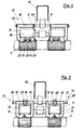
- die Ansicht des Ausgangswalzenpaares eines Streckwerkes in Laufrichtung der Lunte mit einem Luntenverdichter mit einteiligem Verdichtungstrichter;
- Fig. 3
- die Ansicht des Ausgangswalzenpaares eines Streckwerkes in Laufrichtung der Lunte mit einem Luntenverdichter mit zweiteiligem Verdichtungstrichter;
- Fig. 4
- die Ansicht des Ausgangswalzenpaares eines Streckwerkes in Darstellung wie in den Fig. 2 und 3 mit Luntenverdichtern für das Spinnzwirnen;
- Fig. 5
- die Ansicht des Ausgangswalzenpaares eines Streckwerkes in Darstellung wie in den Fig. 2 bis 4 mit Luntenverdichtern für das Herstellen von Core-Garn.
Wie aus den Fig. 2 und 3 erkennbar, sind die Haltearme 15 zu diesem Zweck winkelartig ausgebildet.
- 1, 2, 3
- Walzenpaare
- 4
- Unterwalzen
- 5
- Oberwalzen
- 6, 7
- Lagerschlitten
- 8
- Stanze
- 9
- Tragstange
- 10
- Trag- und Belastungsarm
- 11
- Unterriemchen
- 12
- Oberriemchen
- 13
- Luntenverdichter
- 14, 14'
- Verdichtungstrichter
- 15, 15'
- Haltearm
- 16, 16'
- Lagerbüchse
- 17
- Haltestange
- 18, 19
- Elemente des Verdichtungstrichters
- 20
- Klemmscheibe
- 21, 22
- Stege
- 23
- Leitkanten
- 24
- Trennwand
- 25
- Nutrolle
Claims (6)
- Luntenverdichter (13) in Streckwerken von Spinnmaschinen, das ein von einem Riemchenpaar (11, 12) und einem diesem nachgeordneten Walzenpaar (4, 5) gegebildetes Streckfeld aufweist, wobei ein pendelnd an einer an einem Trag- und Belastungsarm (10) gehalterten Halte- bzw. Lagerstange (17) gelagerter, einteiliger oder zweiteiliger Verdichtungstrichter (14, 14') in dem Zwickel am Einlauf des nachgeordneten Walzenpaares liegt, wobei der zweiteilige Verdichtungstrichter (14, 14') mit unabhängig voneinander gehaltenen Teilstücken (18, 19) im Zusammenwirken das Trichterelement (18, 19) ausbildet, und jeder einstückige Teil des Verdichtungstrichters eine Lagerbuchse (16, 16') und ein Trichterelement (18, 19) aufweist, die über einen Haltearm (15, 15') miteinander verbunden sind,
dadurch gekennzeichnet, daß
der Haltearm (15, 15') das Oberriemchen (12) und/oder die Oberwalze (5) des nachgeordneten Walzenpaares (3) seitlich umgreift. - Luntenverdichter nach Anspruch 1,
dadurch gekennzeichnet, daß
der Verdichtungstrichter (14) zweiteilig ausgebildet ist und die beiden Trichterelemente (18, 19) mittels je eines Haltearmes (15, 15') mit der Haltestange (17) verbunden sind. - Luntenverdichter nach Anspruch 1,
dadurch gekennzeichnet, daß
der Verdichtungstrichter (14) einstückig ausgebildet ist und mit nur einem Haltearm (15) mit seiner Halterung (17) verbunden ist. - Luntenverdichter nach Anspruch 3, in einem Streckwerk mit Oberwalzenzwillingen,
dadurch gekennzeichnet, daß der Haltearm (15) eines Verdichtungstrichters (14) das Oberriemchen (12) und/oder die Oberwalze (5) des nachgeordneten Walzenpaares (3) auf dessen bzw. deren frei liegender Seite umgreift. - Luntenverdichter nach einem oder mehreren der vorhergehenden Ansprüche,
dadurch gekennzeichnet, daß
ein einstückig ausgebildeter Verdichtungstrichter (13) auf seiner Oberseite in eine dünne Trennwand (24) übergeht, die sich in den Zwischenraum zwischen dem Oberriemchen (12) und der Ausgangs-Oberwalze (5) erstreckt. - Luntenverdichter nach einem oder mehreren der vorhergehenden Ansprüche,
dadurch gekennzeichnet, daß
ein einstückiger Luntenverdichter (13) mittels zweier Haltearme (15, 15') mit zwei Lagerbüchsen (16, 16') verbunden ist, zwischen denen eine zum Führen eines Kernfadens geeignete Nutrolle (25) auf der Haltestange (17) drehbar und verschiebbar gelagert ist.
Applications Claiming Priority (4)
| Application Number | Priority Date | Filing Date | Title |
|---|---|---|---|
| DE19730763 | 1997-07-17 | ||
| DE19730763 | 1997-07-17 | ||
| DE19756394 | 1997-12-18 | ||
| DE19756394A DE19756394C2 (de) | 1997-07-17 | 1997-12-18 | Luntenverdichter in einem Streckwerk einer Spinnmaschine |
Publications (3)
| Publication Number | Publication Date |
|---|---|
| EP0893519A2 EP0893519A2 (de) | 1999-01-27 |
| EP0893519A3 EP0893519A3 (de) | 2000-02-23 |
| EP0893519B1 true EP0893519B1 (de) | 2002-11-06 |
Family
ID=26038383
Family Applications (1)
| Application Number | Title | Priority Date | Filing Date |
|---|---|---|---|
| EP98112916A Expired - Lifetime EP0893519B1 (de) | 1997-07-17 | 1998-07-11 | Luntenverdichter in einem Streckwerk einer Spinnmaschine |
Country Status (3)
| Country | Link |
|---|---|
| US (1) | US5915510A (de) |
| EP (1) | EP0893519B1 (de) |
| JP (1) | JPH1193024A (de) |
Cited By (1)
| Publication number | Priority date | Publication date | Assignee | Title |
|---|---|---|---|---|
| CN101139759B (zh) * | 2006-09-04 | 2011-11-23 | 里特机械公司 | 纺纱机牵伸装置中的集棉装置 |
Families Citing this family (9)
| Publication number | Priority date | Publication date | Assignee | Title |
|---|---|---|---|---|
| DE19815052B4 (de) * | 1998-04-03 | 2005-12-15 | Saurer Gmbh & Co. Kg | Verfahren zum Herstellen eines Garnes und Spinnmaschine hierfür |
| DE19815049B4 (de) * | 1998-04-03 | 2004-08-19 | Saurer Gmbh & Co. Kg | Verfahren zum Herstellen eines Garnes und Spinnmaschine hierfür |
| IT1320413B1 (it) * | 2000-06-08 | 2003-11-26 | Marzoli Spa | Telaio di posizionamento per gruppi di stiro e di compattazione difasci di fibre tessili. |
| DE10346258A1 (de) * | 2003-09-24 | 2005-04-21 | Stahlecker Gmbh Wilhelm | Streckwerk für Spinnmaschinen |
| DE102007049337A1 (de) * | 2007-10-12 | 2009-04-16 | Wilhelm Stahlecker Gmbh | Streckwerk zum Verziehen eines Faserverbandes |
| DE102008057617A1 (de) * | 2008-04-24 | 2009-11-05 | Wilhelm Stahlecker Gmbh | Verdichtereinheit und Druckwalzenaggregat für ein Streckwerk einer Textilmaschine |
| WO2010143098A1 (en) * | 2009-06-08 | 2010-12-16 | Cengiz Ulusoy | A compactor to be used in compact yarn machines |
| DE102015112662A1 (de) * | 2015-07-31 | 2017-02-02 | Maschinenfabrik Rieter Ag | Verdichtereinheit für ein Streckwerk einer Textilmaschine |
| DE102018112422A1 (de) * | 2018-05-24 | 2019-11-28 | Saurer Spinning Solutions Gmbh & Co. Kg | Streckwerk sowie Steckwerkeinheit für eine Spinnmaschine |
Family Cites Families (6)
| Publication number | Priority date | Publication date | Assignee | Title |
|---|---|---|---|---|
| DE1785119U (de) * | 1959-01-13 | 1959-03-12 | Skf Kugellagerfabriken Gmbh | Luntenverdichter fuer spinnereimaschinen-streckwerke. |
| DE1825759U (de) * | 1960-12-02 | 1961-01-26 | Skf Kugellagerfabriken Gmbh | Verdichter fuer spinnereimaschinen - streckwerke. |
| GB2089845B (en) * | 1980-11-14 | 1985-08-21 | Murata Machinery Ltd | Drafting method and apparatus in spinning machine |
| AT398086B (de) * | 1993-02-15 | 1994-09-26 | Fehrer Ernst | Streckwerk für eine ringspinnvorrichtung |
| US5577298A (en) * | 1994-03-17 | 1996-11-26 | Hollingsworth Saco Lowell, Inc. | Condenser and method of thread-up |
| DE19537470A1 (de) * | 1995-10-07 | 1997-05-07 | Stahlecker Fritz | Streckwerk für Spinnereimaschinen |
-
1998
- 1998-07-11 EP EP98112916A patent/EP0893519B1/de not_active Expired - Lifetime
- 1998-07-13 JP JP10197704A patent/JPH1193024A/ja not_active Withdrawn
- 1998-07-17 US US09/118,622 patent/US5915510A/en not_active Expired - Fee Related
Cited By (1)
| Publication number | Priority date | Publication date | Assignee | Title |
|---|---|---|---|---|
| CN101139759B (zh) * | 2006-09-04 | 2011-11-23 | 里特机械公司 | 纺纱机牵伸装置中的集棉装置 |
Also Published As
| Publication number | Publication date |
|---|---|
| EP0893519A3 (de) | 2000-02-23 |
| US5915510A (en) | 1999-06-29 |
| JPH1193024A (ja) | 1999-04-06 |
| EP0893519A2 (de) | 1999-01-27 |
Similar Documents
| Publication | Publication Date | Title |
|---|---|---|
| EP0635590B2 (de) | Doppelriemchen-Streckwerk | |
| EP0986659B1 (de) | Verfahren und spinnmaschine zum herstellen von coregarn | |
| DE4447969B4 (de) | Spinnmaschine mit Saugluftleitmitteln zur Faserverband-Kondensation | |
| DE4426278B4 (de) | Spinnmaschine mit Kondensationsstufe | |
| EP0947614B1 (de) | Spinnmaschine mit einem eine Saugwalze aufweisenden Streckwerk | |
| EP1526194A2 (de) | Spinnmaschine mit einer Verdichtungseinrichtung | |
| DE10236450A1 (de) | Spinnmaschine mit einem Mehrstufen-Verdichtungs-Streckwerk | |
| DE4032940A1 (de) | Vorrichtung zum pneumatischen falschdrallspinnen | |
| EP0893519A2 (de) | Luntenverdichter in einem Streckwerk einer Spinnmaschine | |
| WO1981003501A1 (fr) | Metier a filer, de preference metier continu a anneau | |
| EP1302572A2 (de) | Spinnmaschine zum Herstellen von Coregarn | |
| EP3730681A1 (de) | Riemchenstreckwerk | |
| DE102004026519A1 (de) | Vorrichtung an einer Spinnmaschine zum Verstrecken und Verdichten eines Stapelfaserverbandes | |
| DE19815052B4 (de) | Verfahren zum Herstellen eines Garnes und Spinnmaschine hierfür | |
| DE10252631A1 (de) | Spinnmaschine mit Verdichtungseinrichtung | |
| DE19815049B4 (de) | Verfahren zum Herstellen eines Garnes und Spinnmaschine hierfür | |
| DE19805397A1 (de) | Spinnmaschine mit Verdichtungseinrichtung | |
| DE19623824A1 (de) | Spinnmaschine mit einer der Faserbandkonzentration dienenden Kondensationsstufe auf dem Umfang einer am Ausgang eines Mehrstufen-Streckwerks vorgesehenen Saugwalze | |
| EP2682509A2 (de) | Streckwerk für eine Spinnmaschine | |
| DE10154127A1 (de) | Vorrichtung an einer Spinnmaschine zum Verdichten eines Faserverbandes | |
| DE19756394C2 (de) | Luntenverdichter in einem Streckwerk einer Spinnmaschine | |
| EP1921184A2 (de) | Luntenführer für ein Streckwerk | |
| DE19805398A1 (de) | Spinnmaschine mit Verdichtungseinrichtung | |
| EP3688209B1 (de) | Verdichtereinrichtung | |
| EP1654407B1 (de) | Vliesführungsvorrichtung für eine textilmaschine sowie textilmaschine |
Legal Events
| Date | Code | Title | Description |
|---|---|---|---|
| PUAI | Public reference made under article 153(3) epc to a published international application that has entered the european phase |
Free format text: ORIGINAL CODE: 0009012 |
|
| AK | Designated contracting states |
Kind code of ref document: A2 Designated state(s): CH DE ES IT LI |
|
| AX | Request for extension of the european patent |
Free format text: AL;LT;LV;MK;RO;SI |
|
| PUAL | Search report despatched |
Free format text: ORIGINAL CODE: 0009013 |
|
| AK | Designated contracting states |
Kind code of ref document: A3 Designated state(s): AT BE CH CY DE DK ES FI FR GB GR IE IT LI LU MC NL PT SE |
|
| AX | Request for extension of the european patent |
Free format text: AL;LT;LV;MK;RO;SI |
|
| 17P | Request for examination filed |
Effective date: 20000309 |
|
| AKX | Designation fees paid |
Free format text: CH DE ES IT LI |
|
| 17Q | First examination report despatched |
Effective date: 20020111 |
|
| GRAG | Despatch of communication of intention to grant |
Free format text: ORIGINAL CODE: EPIDOS AGRA |
|
| GRAG | Despatch of communication of intention to grant |
Free format text: ORIGINAL CODE: EPIDOS AGRA |
|
| GRAH | Despatch of communication of intention to grant a patent |
Free format text: ORIGINAL CODE: EPIDOS IGRA |
|
| GRAH | Despatch of communication of intention to grant a patent |
Free format text: ORIGINAL CODE: EPIDOS IGRA |
|
| GRAA | (expected) grant |
Free format text: ORIGINAL CODE: 0009210 |
|
| AK | Designated contracting states |
Kind code of ref document: B1 Designated state(s): CH DE ES IT LI |
|
| REG | Reference to a national code |
Ref country code: CH Ref legal event code: EP |
|
| REF | Corresponds to: |
Ref document number: 59806153 Country of ref document: DE Date of ref document: 20021212 |
|
| PG25 | Lapsed in a contracting state [announced via postgrant information from national office to epo] |
Ref country code: ES Free format text: LAPSE BECAUSE OF FAILURE TO SUBMIT A TRANSLATION OF THE DESCRIPTION OR TO PAY THE FEE WITHIN THE PRESCRIBED TIME-LIMIT Effective date: 20030529 |
|
| PLBE | No opposition filed within time limit |
Free format text: ORIGINAL CODE: 0009261 |
|
| STAA | Information on the status of an ep patent application or granted ep patent |
Free format text: STATUS: NO OPPOSITION FILED WITHIN TIME LIMIT |
|
| 26N | No opposition filed |
Effective date: 20030807 |
|
| PGFP | Annual fee paid to national office [announced via postgrant information from national office to epo] |
Ref country code: DE Payment date: 20040903 Year of fee payment: 7 |
|
| PGFP | Annual fee paid to national office [announced via postgrant information from national office to epo] |
Ref country code: CH Payment date: 20050718 Year of fee payment: 8 |
|
| PG25 | Lapsed in a contracting state [announced via postgrant information from national office to epo] |
Ref country code: DE Free format text: LAPSE BECAUSE OF NON-PAYMENT OF DUE FEES Effective date: 20060201 |
|
| PG25 | Lapsed in a contracting state [announced via postgrant information from national office to epo] |
Ref country code: LI Free format text: LAPSE BECAUSE OF NON-PAYMENT OF DUE FEES Effective date: 20060731 Ref country code: CH Free format text: LAPSE BECAUSE OF NON-PAYMENT OF DUE FEES Effective date: 20060731 |
|
| PGFP | Annual fee paid to national office [announced via postgrant information from national office to epo] |
Ref country code: IT Payment date: 20060731 Year of fee payment: 9 |
|
| REG | Reference to a national code |
Ref country code: CH Ref legal event code: PL |
|
| PG25 | Lapsed in a contracting state [announced via postgrant information from national office to epo] |
Ref country code: IT Free format text: LAPSE BECAUSE OF NON-PAYMENT OF DUE FEES Effective date: 20070711 |