EP0892689B1 - Verfahren zum erhöhen der wandungsstärke bei hohlprofilen - Google Patents
Verfahren zum erhöhen der wandungsstärke bei hohlprofilen Download PDFInfo
- Publication number
- EP0892689B1 EP0892689B1 EP97914243A EP97914243A EP0892689B1 EP 0892689 B1 EP0892689 B1 EP 0892689B1 EP 97914243 A EP97914243 A EP 97914243A EP 97914243 A EP97914243 A EP 97914243A EP 0892689 B1 EP0892689 B1 EP 0892689B1
- Authority
- EP
- European Patent Office
- Prior art keywords
- section
- hollow
- deformation
- hollow section
- die
- Prior art date
- Legal status (The legal status is an assumption and is not a legal conclusion. Google has not performed a legal analysis and makes no representation as to the accuracy of the status listed.)
- Expired - Lifetime
Links
Images

Classifications
-
- B—PERFORMING OPERATIONS; TRANSPORTING
- B21—MECHANICAL METAL-WORKING WITHOUT ESSENTIALLY REMOVING MATERIAL; PUNCHING METAL
- B21D—WORKING OR PROCESSING OF SHEET METAL OR METAL TUBES, RODS OR PROFILES WITHOUT ESSENTIALLY REMOVING MATERIAL; PUNCHING METAL
- B21D26/00—Shaping without cutting otherwise than using rigid devices or tools or yieldable or resilient pads, i.e. applying fluid pressure or magnetic forces
- B21D26/02—Shaping without cutting otherwise than using rigid devices or tools or yieldable or resilient pads, i.e. applying fluid pressure or magnetic forces by applying fluid pressure
- B21D26/033—Deforming tubular bodies
-
- B—PERFORMING OPERATIONS; TRANSPORTING
- B21—MECHANICAL METAL-WORKING WITHOUT ESSENTIALLY REMOVING MATERIAL; PUNCHING METAL
- B21J—FORGING; HAMMERING; PRESSING METAL; RIVETING; FORGE FURNACES
- B21J5/00—Methods for forging, hammering, or pressing; Special equipment or accessories therefor
- B21J5/06—Methods for forging, hammering, or pressing; Special equipment or accessories therefor for performing particular operations
- B21J5/08—Upsetting
-
- B—PERFORMING OPERATIONS; TRANSPORTING
- B21—MECHANICAL METAL-WORKING WITHOUT ESSENTIALLY REMOVING MATERIAL; PUNCHING METAL
- B21K—MAKING FORGED OR PRESSED METAL PRODUCTS, e.g. HORSE-SHOES, RIVETS, BOLTS OR WHEELS
- B21K21/00—Making hollow articles not covered by a single preceding sub-group
- B21K21/12—Shaping end portions of hollow articles
-
- F—MECHANICAL ENGINEERING; LIGHTING; HEATING; WEAPONS; BLASTING
- F16—ENGINEERING ELEMENTS AND UNITS; GENERAL MEASURES FOR PRODUCING AND MAINTAINING EFFECTIVE FUNCTIONING OF MACHINES OR INSTALLATIONS; THERMAL INSULATION IN GENERAL
- F16L—PIPES; JOINTS OR FITTINGS FOR PIPES; SUPPORTS FOR PIPES, CABLES OR PROTECTIVE TUBING; MEANS FOR THERMAL INSULATION IN GENERAL
- F16L13/00—Non-disconnectable pipe joints, e.g. soldered, adhesive, or caulked joints
- F16L13/14—Non-disconnectable pipe joints, e.g. soldered, adhesive, or caulked joints made by plastically deforming the material of the pipe, e.g. by flanging, rolling
-
- Y—GENERAL TAGGING OF NEW TECHNOLOGICAL DEVELOPMENTS; GENERAL TAGGING OF CROSS-SECTIONAL TECHNOLOGIES SPANNING OVER SEVERAL SECTIONS OF THE IPC; TECHNICAL SUBJECTS COVERED BY FORMER USPC CROSS-REFERENCE ART COLLECTIONS [XRACs] AND DIGESTS
- Y10—TECHNICAL SUBJECTS COVERED BY FORMER USPC
- Y10T—TECHNICAL SUBJECTS COVERED BY FORMER US CLASSIFICATION
- Y10T29/00—Metal working
- Y10T29/49—Method of mechanical manufacture
- Y10T29/49805—Shaping by direct application of fluent pressure
-
- Y—GENERAL TAGGING OF NEW TECHNOLOGICAL DEVELOPMENTS; GENERAL TAGGING OF CROSS-SECTIONAL TECHNOLOGIES SPANNING OVER SEVERAL SECTIONS OF THE IPC; TECHNICAL SUBJECTS COVERED BY FORMER USPC CROSS-REFERENCE ART COLLECTIONS [XRACs] AND DIGESTS
- Y10—TECHNICAL SUBJECTS COVERED BY FORMER USPC
- Y10T—TECHNICAL SUBJECTS COVERED BY FORMER US CLASSIFICATION
- Y10T29/00—Metal working
- Y10T29/49—Method of mechanical manufacture
- Y10T29/4998—Combined manufacture including applying or shaping of fluent material
- Y10T29/49982—Coating
Definitions
- the invention relates to a method for producing an area increased wall thickness on an elongated hollow profile and on a Device for performing the method, according to the preamble of Claim 1 and 7 respectively.
- German patent application 44 37 395 A1 describes a method for Deforming a pipe end in which the pipe to be deformed is internal and Axial pressure is exposed, the pipe in one of the pipe outer dimensions appropriate die is determined and also in the to deforming end area of the tube with one on the after the final dimensions of the tube provided for the deformation process is matched profile and the tube over at least one Axial piston an end pressure and at the same time at least by means of fluid is subjected to radial pressure in the area to be deformed.
- the patent application DE 44 37 395 A1 deals primarily with the plastic deformation of pipe ends for the production of mass-optimized and durable exhaust systems for internal combustion engines. Areas of such assemblies with functionally changed Cross-sectional dimensions serve, for example, the purpose of Fastening special machine elements or assemblies. Such assemblies and machine elements can u. a. silencers, Catalysts or connecting flanges.
- the invention has for its object the design options of known method according to the preamble of claim 1 increase to an area of increased wall thickness along an elongated To produce hollow profile. A change in the internal cross section of the Hollow profiles should not take place.
- Modifications do not extend the entire length of a hollow profile with an increased Wall thickness, but rather any one Area between the profile ends, with the same internal cross-section.
- the hollow profile itself can have any cross-sectional shape, (e.g. rectangular, as described in US Pat. No. 5,203,194; circular, polygonal, open or closed, etc.). For this it is only necessary to die or to form axial pistons in the same way.
- the hollow profile can also consist of a metallic as well consist of a non-metallic material (e.g. plastic).
- Claim 7 claims one for performing the method particularly suitable device.
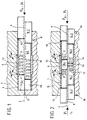
- the hollow profile 1 is a hollow profile 1, for example a steel tube, in a divided hollow die 2 inserted, the die parting plane 3 to The plane of the drawing is orthogonal, the longitudinal axis 4 of the hollow profile 1 cuts.
- the hollow profile 1 extends so far into the cavity 10 of the Hollow die 2 in that it abuts the bottom 5 at the end.
- the divided hollow die has approximately in the central region of the hollow profile 1 2 all around a cross-sectional expansion, so that between the External wall of the hollow profile 1 and the expanded in this area Inner diameter of the hollow die 2 forms an intermediate space 6.
- the Transition from the smaller to the larger diameter is with the holding edge 7 each at an angle of approx. 30 ° to the vertical to Longitudinal axis 4 formed.
- the tool set also includes an axial piston 8, which has a through axial bore 9 is equipped for a fluid.
- Hydraulic fluid is suitable, for example, water, preferably water with synthetic additives.
- the profiled axial piston 8 consists of a front one into the hollow profile 1 to be introduced and adapted in shape Piston part 8.1, to which a rear, the dimensions of the cavity 10th adjusted piston part 8.2 connects.
- the transition from the small to the The larger cross section of the axial piston 8 is than the sealing shoulder 12 trained, the axial cutting surface slightly (z. B. 15 °) to Vertical of the longitudinal axis 4 of the axial piston 8 is inclined.
- the axial piston 8 has the hollow die in the area of the intermediate space 6 2 a number (e.g. six) of rows of radial radial arrangements Bores 13 between the axial bore 9 and the peripheral surface of the axial piston 8 extend.
- Each row of holes lies on one Vertical and consists of a number (e.g. six) of single holes that have an even offset (e.g. angle 60 °) to each other.
- the axial piston 8 After its contact with the sealing shoulder 12 on the end face of the hollow profile 1 (the end of the front piston part 8.1 lies approximately in the region of the front holding edge 7 of the intermediate space 6), the axial piston 8 is initially subjected to an axial thrust force F A (e.g. 5 kN). Then the fluid is pumped through the axial piston 8 through the axial bore 9 and then loaded with a certain pressure (eg 0.5 MPa). In this situation, a press-fit area (cavity 10) is formed between the end face of the axial piston 8 and the bottom 5 of the hollow die 2, in which the hollow profile 1 lying against the die wall is supported against buckling. The fluid is also present via the radial bores 9 on the area of the hollow profile 1 to be compressed.
- F A e.g. 5 kN
- a certain pressure eg 0.5 MPa
- the plastic deformation takes place of the hollow profile 1 in the area to be reshaped until the space 6 is completely filled.
- the wall-reinforced area 14 of the hollow profile 1 (see lower part of FIG. 1) has an unchanged internal cross section, but a z. B. three millimeters thick wall.
- the axial piston 8 is removed from the divided hollow die 2 with simultaneous expansion of the fluid moved out. After the hollow matrix parts have been moved apart, this can be done reshaped hollow profile 1 removed and then continue if necessary processed (e.g. bent, with other components by welding connected, etc.).
- a Upsetting a wall reinforcement of a hollow profile 1 in some areas reached. It takes place in the upsetting area under the effect of the radial Exposure to the fluid also a tangential load on the Hollow section wall in the course of the expansion process and at the same time the axial pressure load due to the thrust of the axial piston 8 instead of.
- the resulting multi-dimensional load exceeds defines the elastic deformation resistance and leads to the desired one plastic deformation.
- the radial bores 9 may be dispensed with can because of the existing dimensional tolerance between the front Piston part 8.1 and the inner wall of the hollow profile 1 and thus accompanying certain leakage of the radial pressure build-up by the Fluid and thus the radial load on the hollow profile 1 in the area of Space 6 is given anyway.
- Fig. 2 shows a modified embodiment of the tool for Production of an increase in wall thickness in the central area of the Hollow section 1. Essentially, the above Comments on the embodiment according to 1 can be used, which is why the same reference numbers are used at the appropriate place be used.
- a split die 15 is used, the parting plane of which runs along the longitudinal axis 4.
- two axial pistons 16 are now used, each consisting of a front piston part 16.1 and a rear piston part 16.2.
- both axial pistons 16 can move towards one another (thrust force F A ), in each case with the simultaneous application of the fluid pressure P i .
- thrust force F A thrust force
- P i fluid pressure
- the divided die 18 is in the area of said End of the profile equipped with a corresponding cross-sectional expansion, so that another space 20 is created, which later, after the Forming, with the material of the hollow profile 1 is filled.
- the boiling point of the fluid e.g. water
- the boiling point of the fluid e.g. water
- the hollow profile 1 in the area of the intermediate space 6 has a slightly smaller wall thickness from the outset or is annealed (hollow profile made of metal), so that's why "More willing to deform" than in the area of the space 20, that is at the end of the profile that is also to be formed.
- the Hollow profile 1 could also prove useful if at least two areas of the Hollow section 1 should have an increased wall thickness and at the end of the section itself no increase in wall thickness is provided.
Landscapes
- Engineering & Computer Science (AREA)
- Mechanical Engineering (AREA)
- General Engineering & Computer Science (AREA)
- Physics & Mathematics (AREA)
- Fluid Mechanics (AREA)
- Forging (AREA)
- Shaping Metal By Deep-Drawing, Or The Like (AREA)
Description
- Fig. 1
- eine Vorrichtung mit eingelegtem und zu verformendem Hohlprofil mit einem Axialkolben in einer Ausgangs- bzw. einer Endstellung,
- Fig. 2
- eine abgewandelte Vorrichtung mit zwei gegenüberliegend angeordneten Axialkolben in Ausgangs- bzw. Endstellung und
- Fig. 3
- eine nochmals abgewandelte Vorrichtung, wiederum mit zwei gegenüberliegend angeordneten Axialkolben und zwei umzuformenden Hohlprofilbereichen.
Claims (8)
- Verfahren zum Herstellen eines Bereiches erhöhter Wandungsstärke an einem länglichen Hohlprofil (1), welches hierfür einem Radial- und Axialdruck ausgesetzt und dabei plastisch verformt wird, wobei das Hohlprofil (1) in einer den Profilaußenmaßen entsprechenden Matrize (2; 15; 18) festgelegt wird
dadurch gekennzeichnet, daß im Verformungsbereich die Matrize (2; 15; 18) mit einer auf die nach dem Verformungsvorgang vorgesehenen Enddimensionen des Hohlprofiles (1) abgestimmten Querschnittserweiterung versehen wird und daß die Verformung zum Erreichen einer erhöhten Wandstärke (14) in einem zwischen den Profilenden gelegenen Bereich erfolgt. - Verfahren nach Anspruch 1, dadurch gekennzeichnet, daß die Verformung sowohl in einem zwischen den Profilenden gelegenen Bereich als auch an mindestens einem der beiden Profilenden erfolgt.
- Verfahren nach Anspruch 2, dadurch gekennzeichnet, daß die Verformung der Anzahl von Profilbereichen in einem Arbeitsgang erfolgt.
- Verfahren nach Anspruch 1, gekennzeichnet durch eine unterschiedliche Ausgangs-Wandstärke des Hohlprofiles (1) zum Herbeiführen einer über die Länge des Hohlprofiles (1) abgestuften Verformungswilligkeit.
- Verfahren nach Anspruch 1, gekennzeichnet durch ein lokales Weichglühen des Hohlprofiles (1) zum Herbeiführen einer über die Länge des Hohlprofiles (1) abgestuften Verformungswilligkeit.
- Verfahren nach Anspruch 1, gekennzeichnet durch lokales Aufbringen von reibungsmindernden Beschichtungen zum Herbeiführen einer über die Länge des Hohlprofiles (1) abgestuften Verformungswilligkeit.
- Vorrichtung zum Herstellen eines Bereiches erhöhter Wandungsstärke an einem länglichen Hohlprofil (1), mit Mitteln zum Einleiten eines Radialund Axialdruckes zur plastischen Verformung des Hohlprofiles (1), wobei das Hohlprofil (1) in einer den Profilaußenmaßen entsprechenden Matrize (2; 15; 18) festgelegt wird, dadurch gekennzeichnet, daß ein zwischen den Profilenden eines eingelegten Hohlprofiles (1) gelegener Bereich einer geteilten Hohlmatrize (2;15;18) eine den vorgesehenen Enddimensionen des Hohlprofiles (1) entsprechende Querschnittserweiterung (6) aufweist, daß ein oder zwei einander gegenüberliegend angeordnete und innerhalb eines Hohlraumes (10) der geteilten Hohlmatrize (2; 15; 18) bewegbar aufgenommene Axialkolben (8; 16;17) angeordnet sind, die zum Erhöhen der Wandungsstärke die Querschnittserweiterung (6) überfahren.
- Vorrichtung nach Anspruch 7, dadurch gekennzeichnet, daß die Hohlmatrize (18) eine weitere, dem Profilende des Hohlprofiles (1) zugeordnete Querschnittserweiterung (20) aufweist.
Applications Claiming Priority (3)
| Application Number | Priority Date | Filing Date | Title |
|---|---|---|---|
| DE19614656A DE19614656A1 (de) | 1994-10-19 | 1996-04-13 | Verfahren zum Erhöhen der Wandungsstärke bei Hohlprofilen |
| DE19614656 | 1996-04-13 | ||
| PCT/EP1997/001299 WO1997038807A1 (de) | 1996-04-13 | 1997-03-14 | Verfahren zum erhöhen der wandungsstärke bei hohlprofilen |
Publications (2)
| Publication Number | Publication Date |
|---|---|
| EP0892689A1 EP0892689A1 (de) | 1999-01-27 |
| EP0892689B1 true EP0892689B1 (de) | 2002-08-28 |
Family
ID=7791202
Family Applications (1)
| Application Number | Title | Priority Date | Filing Date |
|---|---|---|---|
| EP97914243A Expired - Lifetime EP0892689B1 (de) | 1996-04-13 | 1997-03-14 | Verfahren zum erhöhen der wandungsstärke bei hohlprofilen |
Country Status (5)
| Country | Link |
|---|---|
| US (1) | US6321581B1 (de) |
| EP (1) | EP0892689B1 (de) |
| JP (1) | JP2000508246A (de) |
| ES (1) | ES2179315T3 (de) |
| WO (1) | WO1997038807A1 (de) |
Families Citing this family (1)
| Publication number | Priority date | Publication date | Assignee | Title |
|---|---|---|---|---|
| US7647802B2 (en) * | 2006-08-30 | 2010-01-19 | Sunspring America, Inc. | One-piece flexible tube connector and method of making the same |
Family Cites Families (12)
| Publication number | Priority date | Publication date | Assignee | Title |
|---|---|---|---|---|
| DE291212C (de) * | ||||
| LU30707A1 (de) * | ||||
| US2313116A (en) * | 1940-09-12 | 1943-03-09 | Pittsburgh Steel Co | Method of making tubular axles |
| GB1397354A (en) * | 1972-10-11 | 1975-06-11 | Kao Corp | Compositions for coating metals |
| US4213322A (en) * | 1978-10-16 | 1980-07-22 | Youngstown Sheet And Tube Company | Method and apparatus for upsetting pipe |
| DE2925927A1 (de) * | 1979-06-25 | 1981-01-15 | Mannesmann Ag | Verfahren zur herstellung von gelenkwellen mit verzahnungen aus rohren |
| DE3474524D1 (en) * | 1984-04-11 | 1988-11-17 | Hitachi Ltd | Method and apparatus for increasing thickness of tubular member |
| JPH0661590B2 (ja) * | 1985-05-01 | 1994-08-17 | 豊生ブレ−キ工業株式会社 | ブリ−ダプラグの製造方法 |
| SU1417954A1 (ru) * | 1987-01-04 | 1988-08-23 | Ленинградский Политехнический Институт Им.М.И.Калинина | Способ гидравлической штамповки |
| JPS6444210A (en) * | 1987-08-12 | 1989-02-16 | Nippon Steel Corp | Method and device for manufacturing thick metal pipe |
| JPH01245940A (ja) * | 1988-03-28 | 1989-10-02 | Shinei Sangyo Kk | エアコン用t字管の製造方法 |
| DE4437395A1 (de) * | 1994-10-19 | 1996-05-02 | Werdau Fahrzeugwerk | Verfahren zum Anstauchen von Rohrenden und Vorrichtung zur Durchführung des Verfahrens |
-
1997
- 1997-03-14 EP EP97914243A patent/EP0892689B1/de not_active Expired - Lifetime
- 1997-03-14 ES ES97914243T patent/ES2179315T3/es not_active Expired - Lifetime
- 1997-03-14 JP JP9536680A patent/JP2000508246A/ja active Pending
- 1997-03-14 US US09/171,227 patent/US6321581B1/en not_active Expired - Fee Related
- 1997-03-14 WO PCT/EP1997/001299 patent/WO1997038807A1/de not_active Ceased
Also Published As
| Publication number | Publication date |
|---|---|
| ES2179315T3 (es) | 2003-01-16 |
| WO1997038807A1 (de) | 1997-10-23 |
| EP0892689A1 (de) | 1999-01-27 |
| US6321581B1 (en) | 2001-11-27 |
| JP2000508246A (ja) | 2000-07-04 |
Similar Documents
| Publication | Publication Date | Title |
|---|---|---|
| DE19614656A1 (de) | Verfahren zum Erhöhen der Wandungsstärke bei Hohlprofilen | |
| DE3742496C2 (de) | Verfahren und Vorrichtung zum Herstellen einer Endenverdickung an einem Stahlrohr | |
| EP1479842B1 (de) | Hohlprofil | |
| DE10323693B3 (de) | Blechelemente aus flexibel gewalztem Bandmaterial | |
| DE69312807T2 (de) | Verfahren und Vorrichtung zum Herstellen einer rohrförmigen Zahnstange | |
| DE3223004A1 (de) | Lenkspindel fuer lenkvorrichtungen fuer kraftfahrzeuge sowie verfahren zur herstellung einer solchen lenkspindel | |
| WO2000045056A1 (de) | Stanzniet | |
| DE7935982U1 (de) | Wälzlagerkäfig | |
| EP1954420B1 (de) | Verfahren und vorrichtung zum kernlosen einformen von hohlprofilen | |
| WO2008003305A1 (de) | Verfahren zur herstellung eines rotationssymmetrischen teils und danach hergestelltes teil | |
| DE3019592C2 (de) | Vorrichtung zum Bearbeiten von Stahlrohren | |
| DE102018131967A1 (de) | Verfahren zum Kalibrieren eines gekrümmten metallischen Hohlkammerprofils | |
| DE102011000845B4 (de) | Verfahren zum Biegen und axialen Stauchen eines Rohres und Vorrichtung hierzu | |
| DE4032424C2 (de) | Verfahren und Vorrichtung zur Herstellung von gefalzten Rohren | |
| DE69901702T2 (de) | Herstellungsverfahren für ein rohrförmiges metallisches Bauteil und eine rohrförmige Verbundwelle | |
| DE19851492A1 (de) | Verfahren zum Herstellen eines Bauteils mittels Innenhochdruck-Umformen | |
| DE69322945T2 (de) | Verfahren und Vorrichtung zum Fixieren eines mit zumindest einer zylindrischen Bohrung versehenen metallischen Stückes um ein metallisches Rohr | |
| EP3010664B1 (de) | Vorrichtung zur herstellung mindestens eines hinterschnitts in ein geschlitztes oder geschlossenes blechprofil | |
| DE3900186A1 (de) | Verfahren zur herstellung eines kolbenbolzens | |
| WO1997038807A1 (de) | Verfahren zum erhöhen der wandungsstärke bei hohlprofilen | |
| DE1075082B (de) | Vorrichtung zur Verformung der inneren Oberfläche eines rohrförmigen Werkstückes | |
| EP2205370B1 (de) | Verfahren und vorrichtung zur herstellung eines hohlkörpers und hohlkörper | |
| EP2959985B1 (de) | Profilträger mit einer erhöhten biegefestigkeit aus kaltband sowie verfahren zur herstellung eines solchen | |
| DE102006031503B4 (de) | Verfahren und Vorrichtung zum Biegen von Hohlprofilen mit minimalem Biegeradius | |
| DE102018100542A1 (de) | Verfahren zur Herstellung einer Öffnung in einer Wand eines Hohlprofiles und Hohlprofil, hergestellt nach diesem Verfahren |
Legal Events
| Date | Code | Title | Description |
|---|---|---|---|
| PUAI | Public reference made under article 153(3) epc to a published international application that has entered the european phase |
Free format text: ORIGINAL CODE: 0009012 |
|
| 17P | Request for examination filed |
Effective date: 19980911 |
|
| AK | Designated contracting states |
Kind code of ref document: A1 Designated state(s): DE ES FR GB IT |
|
| GRAG | Despatch of communication of intention to grant |
Free format text: ORIGINAL CODE: EPIDOS AGRA |
|
| 17Q | First examination report despatched |
Effective date: 20011121 |
|
| GRAG | Despatch of communication of intention to grant |
Free format text: ORIGINAL CODE: EPIDOS AGRA |
|
| GRAH | Despatch of communication of intention to grant a patent |
Free format text: ORIGINAL CODE: EPIDOS IGRA |
|
| GRAH | Despatch of communication of intention to grant a patent |
Free format text: ORIGINAL CODE: EPIDOS IGRA |
|
| GRAA | (expected) grant |
Free format text: ORIGINAL CODE: 0009210 |
|
| AK | Designated contracting states |
Kind code of ref document: B1 Designated state(s): DE ES FR GB IT |
|
| REG | Reference to a national code |
Ref country code: GB Ref legal event code: FG4D Free format text: NOT ENGLISH |
|
| REF | Corresponds to: |
Ref document number: 59708072 Country of ref document: DE Date of ref document: 20021002 |
|
| GBT | Gb: translation of ep patent filed (gb section 77(6)(a)/1977) |
Effective date: 20020923 |
|
| ET | Fr: translation filed | ||
| REG | Reference to a national code |
Ref country code: ES Ref legal event code: FG2A Ref document number: 2179315 Country of ref document: ES Kind code of ref document: T3 |
|
| PLBE | No opposition filed within time limit |
Free format text: ORIGINAL CODE: 0009261 |
|
| STAA | Information on the status of an ep patent application or granted ep patent |
Free format text: STATUS: NO OPPOSITION FILED WITHIN TIME LIMIT |
|
| 26N | No opposition filed |
Effective date: 20030530 |
|
| REG | Reference to a national code |
Ref country code: GB Ref legal event code: 732E |
|
| REG | Reference to a national code |
Ref country code: FR Ref legal event code: TP |
|
| PGFP | Annual fee paid to national office [announced via postgrant information from national office to epo] |
Ref country code: ES Payment date: 20100308 Year of fee payment: 14 |
|
| PGFP | Annual fee paid to national office [announced via postgrant information from national office to epo] |
Ref country code: IT Payment date: 20100322 Year of fee payment: 14 Ref country code: FR Payment date: 20100408 Year of fee payment: 14 |
|
| PGFP | Annual fee paid to national office [announced via postgrant information from national office to epo] |
Ref country code: GB Payment date: 20100317 Year of fee payment: 14 |
|
| GBPC | Gb: european patent ceased through non-payment of renewal fee |
Effective date: 20110314 |
|
| REG | Reference to a national code |
Ref country code: FR Ref legal event code: ST Effective date: 20111130 |
|
| PG25 | Lapsed in a contracting state [announced via postgrant information from national office to epo] |
Ref country code: FR Free format text: LAPSE BECAUSE OF NON-PAYMENT OF DUE FEES Effective date: 20110331 |
|
| PG25 | Lapsed in a contracting state [announced via postgrant information from national office to epo] |
Ref country code: GB Free format text: LAPSE BECAUSE OF NON-PAYMENT OF DUE FEES Effective date: 20110314 Ref country code: IT Free format text: LAPSE BECAUSE OF NON-PAYMENT OF DUE FEES Effective date: 20110314 |
|
| REG | Reference to a national code |
Ref country code: ES Ref legal event code: FD2A Effective date: 20120423 |
|
| PG25 | Lapsed in a contracting state [announced via postgrant information from national office to epo] |
Ref country code: ES Free format text: LAPSE BECAUSE OF NON-PAYMENT OF DUE FEES Effective date: 20110315 |
|
| PGFP | Annual fee paid to national office [announced via postgrant information from national office to epo] |
Ref country code: DE Payment date: 20160331 Year of fee payment: 20 |
|
| REG | Reference to a national code |
Ref country code: DE Ref legal event code: R071 Ref document number: 59708072 Country of ref document: DE |