EP0889603A2 - Dispositif d'émission à diversité - Google Patents
Dispositif d'émission à diversité Download PDFInfo
- Publication number
- EP0889603A2 EP0889603A2 EP98112400A EP98112400A EP0889603A2 EP 0889603 A2 EP0889603 A2 EP 0889603A2 EP 98112400 A EP98112400 A EP 98112400A EP 98112400 A EP98112400 A EP 98112400A EP 0889603 A2 EP0889603 A2 EP 0889603A2
- Authority
- EP
- European Patent Office
- Prior art keywords
- signal
- transmission diversity
- antenna
- unique word
- receiving
- Prior art date
- Legal status (The legal status is an assumption and is not a legal conclusion. Google has not performed a legal analysis and makes no representation as to the accuracy of the status listed.)
- Withdrawn
Links
Images


Classifications
-
- H—ELECTRICITY
- H04—ELECTRIC COMMUNICATION TECHNIQUE
- H04B—TRANSMISSION
- H04B7/00—Radio transmission systems, i.e. using radiation field
- H04B7/02—Diversity systems; Multi-antenna system, i.e. transmission or reception using multiple antennas
- H04B7/04—Diversity systems; Multi-antenna system, i.e. transmission or reception using multiple antennas using two or more spaced independent antennas
- H04B7/06—Diversity systems; Multi-antenna system, i.e. transmission or reception using multiple antennas using two or more spaced independent antennas at the transmitting station
- H04B7/0602—Diversity systems; Multi-antenna system, i.e. transmission or reception using multiple antennas using two or more spaced independent antennas at the transmitting station using antenna switching
- H04B7/0608—Antenna selection according to transmission parameters
-
- H—ELECTRICITY
- H04—ELECTRIC COMMUNICATION TECHNIQUE
- H04B—TRANSMISSION
- H04B7/00—Radio transmission systems, i.e. using radiation field
- H04B7/02—Diversity systems; Multi-antenna system, i.e. transmission or reception using multiple antennas
- H04B7/04—Diversity systems; Multi-antenna system, i.e. transmission or reception using multiple antennas using two or more spaced independent antennas
- H04B7/08—Diversity systems; Multi-antenna system, i.e. transmission or reception using multiple antennas using two or more spaced independent antennas at the receiving station
- H04B7/0837—Diversity systems; Multi-antenna system, i.e. transmission or reception using multiple antennas using two or more spaced independent antennas at the receiving station using pre-detection combining
Definitions
- the present invention relates to a transmission diversity apparatus.
- the conventional transmission diversity apparatus is structured as follows:
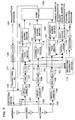
- FIG. 1 is a block diagram showing one example of the conventional diversity apparatus.
- Carrier frequency radio signals received from antennas #1 and #2 are converted to base band signals by receiving RF sections 1 and 2.
- Level detectors 3 and 4 detect field strength of each base band signal for a fixed period of time, and send the detected value to mean value calculators 5 and 6, respectively.
- the mean value calculators 5 and 6 calculate the mean value of the detected values.
- a corrector 7 obtains an output difference of the mean value calculators 5 and 6, and adjusts the characteristics of these level detectors 3 and 4 based on the obtained output difference.
- a comparator 8 compares the receiving level of the level detector 3 with that of the level detector 4, determines which receiving level is higher, and outputs the result to a switching device 9.
- the switching device 9 switches the transmission antenna in accordance with the output of the comparator 8.
- a transmitting signal is input from a terminal 10, modulated by a modulator 11, and converted to a carrier frequency radio signal by a transmitting RF section. Thereafter, the radio signal passes through a receiving/transmitting separator 13 and is transmitted from either one of antennas #1 and #2 switched by the switching device 9.
- the convention transmission diversity apparatus selects the antenna having the highest signal receiving level from the plurality of antennas, thereby transmitting the signal.
- irregularity of the characteristics of the receiving level measuring system is automatically corrected, so that transmission diversity is effectively performed.
- the conventional diversity apparatus selects the transmission antenna based on only the levels of the receiving signals.
- the receiving signals include a desired and an interfering signal. Due to this, even in a case in which the signal level of an interference station is high, there causes a disadvantage in which such an antenna may be selected as an appropriate transmitting antenna.
- An object of the present invention is to provide a transmission diversity apparatus, which can perform appropriate transmission diversity by selecting an antenna whose desired signal power becomes the highest even in a case in which an interference station exists.
- a transmission diversity apparatus comprising a plurality of antennas, each having gain controlling means for controlling receiving signal power; correlation processing means for processing the correlation between an output of the gain controlling means and a reference signal; and standardizing means for standardizing an output of the correlation processing means with a gain control amount of the gain controlling means, the transmission diversity apparatus selecting an antenna, which can obtain an output having a maximum desired signal power among outputs of the standardizing means, as a transmission antenna.
- the transmission diversity apparatus of the present invention has the following structure.
- gain controlling means for controlling receiving signal power
- correlation processing means for processing the correlation between an output of the gain controlling means and a reference signal
- standardizing means for standardizing an output of the correlation processing means with a gain control value of the gain controlling means are provided in each of antennas. Then, an antenna, which can obtain an output in which a desired signal power is the highest of the outputs of the standardizing means, is selected as a transmission antenna.
- the following transmission diversity method is used.
- the correlation between each of the receiving signals of the antennas and a reference signal is processed. Then, an antenna having the highest correlation is selected as a transmission antenna, and the selected antenna is used to transmit a transmitting signal.
- the antenna in which a receiving signal having the high correlation with a predetermined reference signal can be obtained.
- an antenna which can obtain an output in which a desired signal power is the highest of the outputs of the standardizing means, can be selected as a transmission antenna in consideration of a control gain value.
- the reference signal may be used as a unique word signal in a synchronous burst or as a unique word signal in a communication channel signal.
- the use of the unique words in both the synchronous burst as a known symbol and the communication channel can allow an appropriate diversity effect to be obtained.
- the reference signal may be used as a unique word signal in the synchronous burst and as a message signal in the communication channel signal.
- the unique word signal is used as a reference signal.
- the message signal in the receiving signal is used as a reference signal.
- the message signal can be used as a reference signal without referring to the unique word in the communication system in which the unique word signals of the communication channel signals are the same. Even in such a case, the transmission diversity effect can be appropriately obtained.
- the unique word signal in the synchronous burst and the unique word signal in the communication channel signal are used as the reference signal.
- the unique word in the synchronous burst or the message signal in the communication channel is used as the reference signal.
- the reference signal is suitably switched, so that the appropriate transmission diversity can be performed.
- FIG. 2 is a block diagram showing the structure of the transmission diversity apparatus of the Present invention. To simplify the explanation, the following will explain a case in which the number of antennas is three. However, even if the number of antennas is m, the basic operation is the same as the case in which the three antennas is used.
- the apparatus receives carrier frequency signals from antennas #1, #2, and #3.
- the received signals are separated by receiving/transmitting separators 101, 102, 103 of each antenna, and sent to receiving RF sections 104, 105, and 106, respectively.
- the carrier frequency signals are converted to base band signals by the receiving RF sections 104, 105, and 106, respectively.
- AGC circuits 107, 108, and 109 control power levels of the base band signals, respectively.
- A/D converters 110, 111, and 112 convert the respective base band signals to digital signals, respectively.
- Digital signals S1, S2, and S3 are input to a receiving diversity device 113, and decoded by a decoder 114. Thereby, a receiving message can be obtained.
- a switching device 115 switches the unique word in the synchronous burst, which is a known symbol as a reference signal, and the unique word in a communication channel signal, to be sent to a modulator 116.
- the modulator 116 modulates these unique words again, and inputs these modulated unique words to correlation devices 117, 118, and 119.
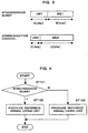
- FIG. 3 shows a frame format of a transmitting signal based on a method for receiving a communication channel signal, which is a message burst, after receiving a synchronous burst at a communication start time.
- the synchronous burst includes a unique word (UW1) of A bit and a control signal (ME) of B bit.
- the communication channel signal includes a unique word (UW2) of C bit and a message signal (ME2) of D bit.
- the unique word (UW1) in the synchronous burst and the unique word (UW2) in the communication channel signal are different from each other in the symbol length and the signal pattern. If both are used as a reference signal without discrimination, a signal of a desired station cannot be extracted from the receiving signal.
- an explanation gives the structure in which the unique word using as a reference signal is switched.
- An operation of this case is shown in FIG. 4. More specifically, it is determined each time whether or not the receiving signal is the synchronous burst (ST101). When the receiving signal is the synchronous burst, the unique word (UW1) in the synchronous burst is used as a reference signal (ST102). When the receiving signal is not the synchronous burst, the unique word (UW2) in the communication channel signal is used as a reference signal (ST103). Thus, the switching device 115 is controlled. A modulation signal of either one of the unique words is input to the correlation devices 117, 118, and 119.
- the correlation devices 117, 118, and 119 process the correlation between the signal modulated again and each of digital signals S1, S2, and S3, which are the outputs of the A/D converters 110, 111, and 112.
- desired signals are D 1 , D 2 , and D 3
- interfering signals are U 1 , U 2 , and U 3
- gains of AGC circuits 107, 108, and 109 are , , and
- an output signal of a modulator 161 is D'.
- Antenna 2: (D 2 +U 2 ) ⁇ D'* D 2 ⁇ D' *
- Antenna 3: (D 3 +U 3 ) ⁇ D'* D 3 ⁇ D' * (where * denotes a complex conjugate).
- the unique word signal pattern of the signal (desired signal) from the desired station and that of the signal (interfering signal) from the interference station are different from each other. Then, if the receiving signal and the interfering signal are correlated using the unique word signal of the desired signal, the correlation becomes substantially close to zero. Therefore, the outputs of the correlation devices 117, 118, and 119 become receiving power of the desired signal.
- standardizing devices 120, 121, and 122 standardize the outputs of the correlation devices 117, 118, and 119 obtained by equations 1 to 3 with control values C1, C2, C3 of the AGC circuits 107, 108, and 109. Thereby, a receiving level estimation value of an actual desired wave is obtained.
- the standardizing process here is one for normalizing the outputs of the correlation devices 117, 118, and 119 as considering the gains of the AGC circuits 107 and 108, and 109.
- a comparator 123 compares the receiving levels of these outputs, and selects a transmission antenna, which has the maximum receiving level estimation value of the desired wave among the outputs N 1 , N 2 , and N 3 of the standardizing devices 120, 121, and 122, and which is suitable for combating with the interfering signal. Then, the comparator 123 outputs the selection result to a switching device 124.
- a modulator 126 modulates a transmitting message input from a terminal 125. Then, the modulated transmitting message is converted to a carrier frequency signal by a transmitting RF section 127.
- the switching device 124 switches the reference signal so as to transmit the carrier frequency signal from any one of the selected transmitting antennas 1, 2, and 3 in accordance with the output of the comparator 123.
- the carrier frequency signal is transmitted through receiving/transmitting separators 101, 102, and 103.
- both the unique word in the synchronous burst, which is the known symbol and the unique word in the communication channel signal are used as reference signals. These signals are appropriately switched in accordance with the receiving signal and the correlation with the receiving signal of each antenna is processed, so that desired signal power of each antenna can be estimated. Then, the antenna having the maximum correlation value is selected, thereby a suitable transmission diversity effect can be obtained even if the interference station exists.
- the antenna 3 is selected as a suitable antenna by the sum of field strength of the receiving signals from a desired station 201 and an interference station 202 as shown in FIG. 5.
- the antenna 1 having the maximum desired signal power among the receiving signals of the desired station 201 and the interference station 202 is selected as a suitable antenna.
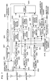
- FIG. 7 is a block diagram showing the other structure of the transmission diversity apparatus of the present invention.
- the unique word which was the known symbol, was used as a reference signal, and the correlation between the receiving signal of each antenna and the reference signal was processed, thereby estimating desired signal power of each antenna. Then, the antenna having the highest correlation value was selected, and the transmitting diversity effect could be obtained even in a case where the interference station existed.
- the unique word (UW1) in the synchronous burst and the message portion (ME2) in the communication channel are switched to each other so as to produce the reference signal.
- signals are received from antenna #1, #2, and #3.
- the received signals are separated by receiving/transmitting separators 301, 302, and 303 of the respective antennas, and sent to the receiving RF sections 304, 305, and 306.
- the carrier frequency signals are converted to the base band signals by the receiving RF sections 304, 305, and 306.
- power levels of the respective base band signals are controlled by AGC circuits 307, 308, and 309, and A/D converters 310, 311, and 312 convert these base band signals to digital signals.
- the digital signals S1, S2, and S3 are received by an interference removing circuit 313 having a receiving diversity function, and decoded by a decoder 314. Thereby, a receiving message can be obtained.
- a switching device 315 changes the unique word in the synchronous burst, which is the known symbol, as a reference signal and the receiving message.
- the unique word and the receiving message are modulated again by a modulator 316, and input to correlation devices 317, 318, and 319.
- the correlation devices 317, 318, and 319 process the correlation between the signals modulated again and the digital signals S1, S2, and S3, which are the outputs of the A/D converters 310, 311, 312.
- Standardizing devices 320, 321, and 322 standardize the outputs of the correlation devices 317, 318, and 319 with control values C1, C2, and C3 of the AGC circuits 307, 308, and 309. Thereby, receiving level estimation values of actual desired waves can be obtained.
- a comparator 323 compares the receiving level estimation values, and selects a transmitting antenna, which has the maximum receiving level estimation value of the desired wave, and which is suitable for combating with the interfering signal. Then, the comparator 323 outputs the selection result to a switching device 324.
- a modulator 326 modulates a transmitting message input from a terminal 325. Then, the modulated transmitting message is converted to a carrier frequency signal by a transmitting RF section 327.
- the switching device 324 switches the reference signal so as to transmit the carrier frequency signal from any one of the selected transmitting antennas 1, 2, and 3 in accordance with the output of the comparator 323.
- the carrier frequency signal is transmitted through receiving/transmitting separators 301, 302, and 303.
- a switching device 615 switches the unique word (UW1) in the synchronous burst and the message portion (ME2) in the communication channel signal. Thereby, the reference signals of the correlation devices 317, 318, and 319 are produced.
- FIG. 8 is the flow chart. More specifically, it is determined each time whether or not the receiving signal is the synchronous burst (ST201). When the receiving signal is the synchronous burst, the unique word (UW1) in the synchronous burst is used as a reference signal (ST202). When the receiving signal is not the synchronous burst, the message portion (UW2) in the communication channel signal is used as a reference signal (ST203). Thus, the switching device 315 is controlled. A modulation signal of either one of unique words is input to the correlation devices 317, 318, and 319.
- the transmitting message can be transmitted from the antenna having the maximum desired signal power at the time of receiving the synchronous burst and at the time of receiving the communication channel.
- the message portion of the receiving signal is not generally the known symbol sequence, the message portion cannot be used as a reference signal.
- an error rate of the message portion is about 10 -2 , the number of errors in one slot is small.
- the signal point position is known instead of the known symbol sequence, the received signal to which the interfering signal of the message portion is added as shown in FIG. 9B is redetermined as being placed at the original signal point position for each quadrant. Thereby, the interfering signal of the message portion can be removed.
- the symbol determined in this way is considered to be substantially correct, and is used as a reference signal.
- the unique word in the synchronous burst having a different unique word pattern and the message portion signal in the communication channel signal from which the interfering signal is removed are compared with each other by use of the receiving signals from the respective antennas.
- the transmitting antenna which has the highest correlation with the desired signal and which has the maximum desired signal power, can be selected even in a case in which there is the interference station having the same unique word pattern as that of the desired station.
- the transmitting antenna can be correctly selected in accordance with the movement of the desired station and the change in the propagation environment.
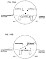
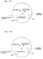
- the suitable antenna is conventionally selected by the following method. More specifically, as shown in FIG. 10A, the antenna is selected by the sum of the field strength of the receiving signals from a desired station 401 and an interference station 402. According to this method, however, an antenna (antenna 3), in which the antenna distance between the desired station 401 and the interference station 402 is the shortest, is selected. When the transmission is performed using the selected antenna 3, an interference to the interference station 402 increases, and a call is cut off in the worst case.
- the antenna 1 having the maximum desired signal power in the receiving signals of the desired station and the interference station 402 is selected as a suitable antenna as shown in FIG.10B.
- the transmission can be performed using the antenna in which the distance between the interference station 402 and the transmitting antenna is long. Therefore, the interference to the interference station 402 is reduced, and the frequency effective use is possible.
- an interference to an interference station 502 can be reduced at the signal reception, and this leads to improvement of the quality of the signal reception.
- a directional antenna having the maximum desired power of a desired station 501 is selected at the signal transmission.
- the transmission diversity apparatus can be applied to a base station apparatus and a mobile station in a radio wave communication system.
- the antenna having the maximum desired signal power is selected, thereby making it possible to obtain the suitable transmission diversity effect using the antenna, which is strongest against the interfering signal even in a case where the interference station exists.
Landscapes
- Engineering & Computer Science (AREA)
- Computer Networks & Wireless Communication (AREA)
- Signal Processing (AREA)
- Radio Transmission System (AREA)
- Mobile Radio Communication Systems (AREA)
- Radio Relay Systems (AREA)
Applications Claiming Priority (3)
| Application Number | Priority Date | Filing Date | Title |
|---|---|---|---|
| JP19496897 | 1997-07-04 | ||
| JP194968/97 | 1997-07-04 | ||
| JP19496897A JP3290926B2 (ja) | 1997-07-04 | 1997-07-04 | 送信ダイバーシチ装置 |
Publications (2)
| Publication Number | Publication Date |
|---|---|
| EP0889603A2 true EP0889603A2 (fr) | 1999-01-07 |
| EP0889603A3 EP0889603A3 (fr) | 2002-07-31 |
Family
ID=16333345
Family Applications (1)
| Application Number | Title | Priority Date | Filing Date |
|---|---|---|---|
| EP98112400A Withdrawn EP0889603A3 (fr) | 1997-07-04 | 1998-07-03 | Dispositif d'émission à diversité |
Country Status (4)
| Country | Link |
|---|---|
| US (1) | US6226508B1 (fr) |
| EP (1) | EP0889603A3 (fr) |
| JP (1) | JP3290926B2 (fr) |
| CN (1) | CN1211115A (fr) |
Cited By (9)
| Publication number | Priority date | Publication date | Assignee | Title |
|---|---|---|---|---|
| WO2003058850A2 (fr) * | 2002-01-07 | 2003-07-17 | Loranet Nv | Dispositif et procede pour l'amelioration de la communication numerique sans fil de l'exterieur vers l'interieur |
| EP1432067A2 (fr) * | 2002-12-20 | 2004-06-23 | Nec Corporation | Telephone cellulaire à circuit de commutation pour antenne et procédé pour commutation pour antenne |
| WO2006093766A1 (fr) * | 2005-02-28 | 2006-09-08 | Cardiac Pacemakers, Inc. | Systeme d'antennes a diversite permettant de communiquer avec les appareils implantables |
| US7392092B2 (en) | 2005-02-28 | 2008-06-24 | Cardiac Pacemakers, Inc. | Method and apparatus for operating a diversity antenna system for communicating with implantable medical device |
| US7610065B2 (en) | 2005-02-28 | 2009-10-27 | Cardiac Pacemakers, Inc. | Method and apparatus for antenna selection in a diversity antenna system for communicating with implantable medical device |
| WO2013140197A1 (fr) * | 2012-03-23 | 2013-09-26 | Sony Mobile Communications Ab | Procédés de substitution d'antennes consistant à comparer des caractéristiques d'efficacité de première et deuxième antennes, et dispositifs électroniques portables associés |
| EP2650965A3 (fr) * | 2012-04-09 | 2014-04-09 | BlackBerry Limited | Performance de liaison montante optimisée par l'intermédiaire d'une sélection d'antenne |
| EP2650966A3 (fr) * | 2012-04-09 | 2014-04-16 | BlackBerry Limited | Performance de liaison montante optimisée par l'intermédiaire d'une sélection d'antenne |
| US9007970B2 (en) | 2012-10-11 | 2015-04-14 | Sony Corporation | Antenna swapping methods including repeatedly swapping between antennas, and related wireless electronic devices |
Families Citing this family (23)
| Publication number | Priority date | Publication date | Assignee | Title |
|---|---|---|---|---|
| US6396457B1 (en) * | 2000-02-29 | 2002-05-28 | Texas Instruments Incorporated | Concentrator for coupling local wireless networks to a wired network |
| JP3679000B2 (ja) | 2000-12-21 | 2005-08-03 | 松下電器産業株式会社 | 無線送信装置及び無線送信方法 |
| US6961545B2 (en) * | 2001-04-09 | 2005-11-01 | Atheros Communications, Inc. | Method and system for providing antenna diversity |
| JP4252802B2 (ja) * | 2001-05-02 | 2009-04-08 | 富士通株式会社 | 送信ダイバーシチシステム |
| WO2003034385A2 (fr) * | 2001-10-19 | 2003-04-24 | Clare Micronix Integrated Systems, Inc. | Systeme et procede de compensation du temps d'exposition pour la resistance de la ligne |
| CN1327730C (zh) * | 2002-07-19 | 2007-07-18 | 国立新加坡大学 | 无线通信设备和方法 |
| US7171161B2 (en) * | 2002-07-30 | 2007-01-30 | Cognio, Inc. | System and method for classifying signals using timing templates, power templates and other techniques |
| US7212788B2 (en) * | 2002-08-13 | 2007-05-01 | Atheros Communications, Inc. | Method and apparatus for signal power loss reduction in RF communication systems |
| US8532588B1 (en) | 2002-08-13 | 2013-09-10 | The Connectivity Patent Trust | Apparatus for signal power loss reduction in RF communication systems |
| US8743837B2 (en) * | 2003-04-10 | 2014-06-03 | Qualcomm Incorporated | Modified preamble structure for IEEE 802.11A extensions to allow for coexistence and interoperability between 802.11A devices and higher data rate, MIMO or otherwise extended devices |
| US7916803B2 (en) | 2003-04-10 | 2011-03-29 | Qualcomm Incorporated | Modified preamble structure for IEEE 802.11a extensions to allow for coexistence and interoperability between 802.11a devices and higher data rate, MIMO or otherwise extended devices |
| TWI288537B (en) * | 2003-06-20 | 2007-10-11 | Realtek Semiconductor Corp | Automatic gain control and antenna diversity method of wireless communication system |
| KR100608740B1 (ko) * | 2003-08-08 | 2006-08-04 | 엘지전자 주식회사 | 휴대단말기의 수신성능 개선장치 및 방법 |
| US7586884B2 (en) * | 2003-08-15 | 2009-09-08 | Qualcomm Incorporated | Joint packet detection in wireless communication system with one or more receiver |
| JP2005260502A (ja) | 2004-03-10 | 2005-09-22 | Nec Corp | 通信装置と通信制御方法 |
| US6946898B1 (en) * | 2004-03-26 | 2005-09-20 | Silicon Laboratories, Inc. | System and method for biasing electrical circuits |
| US7155176B2 (en) * | 2004-04-08 | 2006-12-26 | Skyworks Solutions, Inc. | System for synchronizing a portable transceiver to a network |
| EP1751890B1 (fr) * | 2004-05-27 | 2017-03-01 | QUALCOMM Incorporated | Structure de preambule modifie pour extensions ieee 802.11a permettant la coexistence et l'interoperabilite entre des dispositifs 802.11a et des dispositifs a debit plus eleve, mimo ou presentant d'autres types d'extensions |
| US7835319B2 (en) * | 2006-05-09 | 2010-11-16 | Cisco Technology, Inc. | System and method for identifying wireless devices using pulse fingerprinting and sequence analysis |
| ATE447799T1 (de) * | 2007-02-05 | 2009-11-15 | Research In Motion Ltd | Multimodus-empfänger mit adaptiver modusauswahl |
| US8532211B2 (en) * | 2009-02-20 | 2013-09-10 | Qualcomm Incorporated | Methods and apparatus for power control based antenna switching |
| CN109257082A (zh) * | 2017-07-14 | 2019-01-22 | 中兴通讯股份有限公司 | 一种天线切换处理方法、装置及系统 |
| WO2021189388A1 (fr) * | 2020-03-26 | 2021-09-30 | 华为技术有限公司 | Dispositif de communication sans fil et procédé de commutation d'antenne correspondant |
Citations (2)
| Publication number | Priority date | Publication date | Assignee | Title |
|---|---|---|---|---|
| EP0364190A2 (fr) * | 1988-10-12 | 1990-04-18 | Sumitomo Electric Industries, Ltd. | Procédé et installation d'émission et de réception en diversité |
| US5537672A (en) * | 1992-04-28 | 1996-07-16 | Robert Bosch Gmbh | System for bidirectional data transmission between a beacon and a vehicle |
Family Cites Families (9)
| Publication number | Priority date | Publication date | Assignee | Title |
|---|---|---|---|---|
| JPH0529990A (ja) | 1991-07-18 | 1993-02-05 | Nippon Telegr & Teleph Corp <Ntt> | 送信ダイバーシチ装置 |
| SG66285A1 (en) * | 1993-04-29 | 1999-07-20 | Ericsson Inc | Use of diversity transmission to relax adjacent channel requirements in mobile telephone systems |
| JP3085042B2 (ja) * | 1993-06-29 | 2000-09-04 | 日本電気株式会社 | 干渉波除去装置 |
| JP2876517B2 (ja) * | 1994-02-16 | 1999-03-31 | 松下電器産業株式会社 | Cdma/tdd方式基地局装置およびcdma/tdd方式移動局装置およびcdma/tdd方式無線通信システムおよびcdma/tdd方式無線通信方法 |
| JPH0832498A (ja) | 1994-07-20 | 1996-02-02 | Nippon Telegr & Teleph Corp <Ntt> | 送信ダイバーシチ方式 |
| JPH08195703A (ja) * | 1995-01-17 | 1996-07-30 | Toshiba Corp | 無線通信装置 |
| JPH08321785A (ja) * | 1995-05-24 | 1996-12-03 | Sony Corp | 送信機,受信機,送信方法,受信方法及び伝送方法 |
| JPH0918396A (ja) | 1995-06-30 | 1997-01-17 | Toshiba Corp | 無線通信装置およびその送信ダイバーシチ回路 |
| US5883921A (en) * | 1995-07-31 | 1999-03-16 | Harris Corporation | Short burst acquisition circuit and method for direct sequence spread spectrum links |
-
1997
- 1997-07-04 JP JP19496897A patent/JP3290926B2/ja not_active Expired - Fee Related
-
1998
- 1998-06-25 US US09/104,180 patent/US6226508B1/en not_active Expired - Fee Related
- 1998-07-03 CN CN98115597.9A patent/CN1211115A/zh active Pending
- 1998-07-03 EP EP98112400A patent/EP0889603A3/fr not_active Withdrawn
Patent Citations (2)
| Publication number | Priority date | Publication date | Assignee | Title |
|---|---|---|---|---|
| EP0364190A2 (fr) * | 1988-10-12 | 1990-04-18 | Sumitomo Electric Industries, Ltd. | Procédé et installation d'émission et de réception en diversité |
| US5537672A (en) * | 1992-04-28 | 1996-07-16 | Robert Bosch Gmbh | System for bidirectional data transmission between a beacon and a vehicle |
Non-Patent Citations (1)
| Title |
|---|
| SAWAHASHI M ET AL: "TRANSMITTER DIVERSITY EFFECT IN TDMA/TDD MOBILE RADIO TRANSMISSION" ELECTRONICS LETTERS, IEE STEVENAGE, GB, vol. 28, no. 24, 19 November 1992 (1992-11-19), pages 2201-2202, XP000319624 ISSN: 0013-5194 * |
Cited By (19)
| Publication number | Priority date | Publication date | Assignee | Title |
|---|---|---|---|---|
| WO2003058850A3 (fr) * | 2002-01-07 | 2004-05-06 | Loranet Nv | Dispositif et procede pour l'amelioration de la communication numerique sans fil de l'exterieur vers l'interieur |
| WO2003058850A2 (fr) * | 2002-01-07 | 2003-07-17 | Loranet Nv | Dispositif et procede pour l'amelioration de la communication numerique sans fil de l'exterieur vers l'interieur |
| US7392030B2 (en) | 2002-12-20 | 2008-06-24 | Nec Corporation | Cell phone antenna switching circuit and antenna switching method |
| EP1432067A2 (fr) * | 2002-12-20 | 2004-06-23 | Nec Corporation | Telephone cellulaire à circuit de commutation pour antenne et procédé pour commutation pour antenne |
| EP1432067A3 (fr) * | 2002-12-20 | 2004-11-17 | Nec Corporation | Telephone cellulaire à circuit de commutation pour antenne et procédé pour commutation pour antenne |
| US7925356B2 (en) | 2005-02-28 | 2011-04-12 | Cardiac Pacemakers, Inc. | Method and apparatus for operating a diversity antenna system for communicating with implantable medical device |
| US7392092B2 (en) | 2005-02-28 | 2008-06-24 | Cardiac Pacemakers, Inc. | Method and apparatus for operating a diversity antenna system for communicating with implantable medical device |
| US7610065B2 (en) | 2005-02-28 | 2009-10-27 | Cardiac Pacemakers, Inc. | Method and apparatus for antenna selection in a diversity antenna system for communicating with implantable medical device |
| WO2006093766A1 (fr) * | 2005-02-28 | 2006-09-08 | Cardiac Pacemakers, Inc. | Systeme d'antennes a diversite permettant de communiquer avec les appareils implantables |
| US8238975B2 (en) | 2005-02-28 | 2012-08-07 | Cardiac Pacemakers, Inc. | Method and apparatus for antenna selection in a diversity antenna system for communicating with implantable medical device |
| US8352040B2 (en) | 2005-02-28 | 2013-01-08 | Cardiac Pacemakers, Inc. | Diversity antenna system for communication with an implantable medical device |
| US8509911B2 (en) | 2005-02-28 | 2013-08-13 | Cardiac Pacemakers, Inc. | Method and apparatus for operating a diversity antenna system for communicating with implantable medical device |
| WO2013140197A1 (fr) * | 2012-03-23 | 2013-09-26 | Sony Mobile Communications Ab | Procédés de substitution d'antennes consistant à comparer des caractéristiques d'efficacité de première et deuxième antennes, et dispositifs électroniques portables associés |
| US9240830B2 (en) | 2012-03-23 | 2016-01-19 | Sony Corporation | Antenna swapping methods including comparing performance characteristics of first and second antennas, and related portable electronic devices |
| US9628161B2 (en) | 2012-03-23 | 2017-04-18 | Sony Corporation | Antenna swapping methods including comparing performance characteristics of first and second antennas, and related portable electronic devices |
| EP2650965A3 (fr) * | 2012-04-09 | 2014-04-09 | BlackBerry Limited | Performance de liaison montante optimisée par l'intermédiaire d'une sélection d'antenne |
| EP2650966A3 (fr) * | 2012-04-09 | 2014-04-16 | BlackBerry Limited | Performance de liaison montante optimisée par l'intermédiaire d'une sélection d'antenne |
| US8953474B2 (en) | 2012-04-09 | 2015-02-10 | Blackberry Limited | Optimized uplink performance via antenna selection |
| US9007970B2 (en) | 2012-10-11 | 2015-04-14 | Sony Corporation | Antenna swapping methods including repeatedly swapping between antennas, and related wireless electronic devices |
Also Published As
| Publication number | Publication date |
|---|---|
| EP0889603A3 (fr) | 2002-07-31 |
| JPH1127188A (ja) | 1999-01-29 |
| CN1211115A (zh) | 1999-03-17 |
| JP3290926B2 (ja) | 2002-06-10 |
| US6226508B1 (en) | 2001-05-01 |
Similar Documents
| Publication | Publication Date | Title |
|---|---|---|
| EP0889603A2 (fr) | Dispositif d'émission à diversité | |
| US6806844B2 (en) | Calibration system for array antenna receiving apparatus | |
| US5634204A (en) | Radio communication apparatus | |
| US7379749B2 (en) | Radio terminal apparatus and reception operation control program thereof | |
| US7764930B2 (en) | Data transmission system, data transmitter and data receiver used in the data transmission system | |
| US7369878B2 (en) | Radio base station apparatus, radio terminal apparatus, mobile communication system, and reception operation control program | |
| EP0883207A2 (fr) | Appareil de réception à réseau d'antennes adaptatives | |
| EP2175572A2 (fr) | Appareil et méthode pour transmision et réception | |
| JPH08307333A (ja) | 送信ダイバシティ方式 | |
| EP0926837B1 (fr) | Commande automatique de gain pour un récepteur de transmission à évasion de fréquence | |
| JPH10313472A (ja) | 無線基地局装置および無線端末装置 | |
| US7418242B2 (en) | Transmission device and gain control method | |
| EP1103105A1 (fr) | Appareil et procede pour reguler la puissance d'emission de radiocommunications | |
| US6430173B1 (en) | Reception method and receiver | |
| US7398098B2 (en) | Radio base apparatus, transmission power control method, and transmission power control program | |
| JPH07202785A (ja) | 受信電界レベル検出回路 | |
| JPH07245577A (ja) | ダイバーシチ通信装置 | |
| EP1370104A1 (fr) | Procédé et système pour la détermination d'une antenne d'une station de base radio dans une zone cible pendant un transfert | |
| EP0945999A2 (fr) | Procédé et dispositif de communication mobile pour la sélection de signaux de réception | |
| JPH06132940A (ja) | アンテナ切替ダイバーシチ受信方式 | |
| JPS5941334B2 (ja) | 中間周波合成型ダイバ−シチ受信装置 | |
| JP2001223620A (ja) | 無線電話装置 |
Legal Events
| Date | Code | Title | Description |
|---|---|---|---|
| PUAI | Public reference made under article 153(3) epc to a published international application that has entered the european phase |
Free format text: ORIGINAL CODE: 0009012 |
|
| AK | Designated contracting states |
Kind code of ref document: A2 Designated state(s): AT BE CH CY DE DK ES FI FR GB GR IE IT LI LU MC NL PT SE |
|
| AX | Request for extension of the european patent |
Free format text: AL;LT;LV;MK;RO;SI |
|
| PUAL | Search report despatched |
Free format text: ORIGINAL CODE: 0009013 |
|
| AK | Designated contracting states |
Kind code of ref document: A3 Designated state(s): AT BE CH CY DE DK ES FI FR GB GR IE IT LI LU MC NL PT SE |
|
| AX | Request for extension of the european patent |
Free format text: AL;LT;LV;MK;RO;SI |
|
| RIC1 | Information provided on ipc code assigned before grant |
Free format text: 7H 04B 7/06 A, 7H 04B 7/08 B |
|
| AKX | Designation fees paid | ||
| REG | Reference to a national code |
Ref country code: DE Ref legal event code: 8566 |
|
| STAA | Information on the status of an ep patent application or granted ep patent |
Free format text: STATUS: THE APPLICATION IS DEEMED TO BE WITHDRAWN |
|
| 18D | Application deemed to be withdrawn |
Effective date: 20030201 |