BACKGROUND OF THE INVENTION
Field of the Invention
The present invention relates to a transmission
diversity apparatus.
Description of the Related Art
The conventional transmission diversity
apparatus is structured as follows:
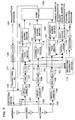
FIG. 1 is a block diagram showing one example
of the conventional diversity apparatus.
Carrier frequency radio signals received from
antennas #1 and #2 are converted to base band signals
by receiving RF sections 1 and 2. Level detectors
3 and 4 detect field strength of each base band signal
for a fixed period of time, and send the detected
value to mean value calculators 5 and 6, respectively.
The mean value calculators 5 and 6
calculate the mean value of the detected values. A
corrector 7 obtains an output difference of the mean
value calculators 5 and 6, and adjusts the
characteristics of these level detectors 3 and 4
based on the obtained output difference.
A comparator 8 compares the receiving level of
the level detector 3 with that of the level detector
4, determines which receiving level is higher, and
outputs the result to a switching device 9. The
switching device 9 switches the transmission
antenna in accordance with the output of the comparator
8.
A transmitting signal is input from a terminal
10, modulated by a modulator 11, and converted to
a carrier frequency radio signal by a transmitting
RF section. Thereafter, the radio signal passes
through a receiving/transmitting separator 13 and
is transmitted from either one of antennas #1 and
#2 switched by the switching device 9.
Thus, the convention transmission diversity
apparatus selects the antenna having the highest
signal receiving level from the plurality of
antennas, thereby transmitting the signal. As a
result, irregularity of the characteristics of the
receiving level measuring system is automatically
corrected, so that transmission diversity is
effectively performed.
The conventional diversity apparatus, however,
selects the transmission antenna based on only the
levels of the receiving signals. The receiving
signals include a desired and an interfering signal.
Due to this, even in a case in which the signal level
of an interference station is high, there causes a
disadvantage in which such an antenna may be
selected as an appropriate transmitting antenna.
SUMMARY OF THE INVENTION
An object of the present invention is to provide
a transmission diversity apparatus, which can
perform appropriate transmission diversity by selecting
an antenna whose desired signal power becomes
the highest even in a case in which an
interference station exists.
In order to achieve the above object, there is
provided a transmission diversity apparatus comprising
a plurality of antennas, each having gain
controlling means for controlling receiving signal
power; correlation processing means for processing
the correlation between an output of the gain
controlling means and a reference signal; and
standardizing means for standardizing an output of
the correlation processing means with a gain control
amount of the gain controlling means, the
transmission diversity apparatus selecting an antenna,
which can obtain an output having a maximum
desired signal power among outputs of the
standardizing means, as a transmission antenna.
BRIEF DESCRIPTION OF THE DRAWINGS
FIG. 1 is a block diagram showing a conventional
transmission diversity apparatus;
FIG. 2 is a block diagram of a first embodiment
according to a diversity apparatus of the present
invention;
FIG. 3 is a view showing a frame format of a
receiving signal according to the first embodiment
of the present invention;
FIG. 4 is a flow chart showing a reference
signal selection according to the first embodiment
of the present invention;
FIG. 5 is a view explaining a method of
selecting a transmission antenna according to the
first embodiment of the present invention;
FIG. 6 is a view explaining a method of
selecting a transmission antenna according to the
first embodiment of the present invention;
FIG. 7 is block diagram of a second embodiment
according to a diversity apparatus of the present
invention;
FIG. 8 is a flow chart showing a reference
signal selection according to the second embodiment
of the present invention;
FIG. 9 is a view explaining a determination of
a signal point position according to the second
embodiment of the present invention;
FIG. 10A is a view explaining an interference
amount to an interference station provided by
transmission of the conventional transmission diversity
apparatus;
FIG. 10B is a view explaining the interference
amount to an interference station provided by
transmission of the transmission diversity
apparatus of the present invention;
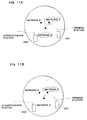
FIG. 11A is a view explaining the interference
amount provided by reception of the transmission
diversity apparatus of the present invention; and
FIG. 11B is a view explaining the interference
amount provided by transmission of the transmission
diversity apparatus of the present invention.
DETAILED DESCRIPTION OF THE
PREFERRED EMBODIMENTS
The transmission diversity apparatus of the
present invention has the following structure.
Specifically, there are provided gain controlling
means for controlling receiving signal
power, correlation processing means for processing
the correlation between an output of the gain
controlling means and a reference signal, and
standardizing means for standardizing an output of
the correlation processing means with a gain control
value of the gain controlling means are provided in
each of antennas. Then, an antenna, which can
obtain an output in which a desired signal power is
the highest of the outputs of the standardizing
means, is selected as a transmission antenna.
In the embodiments of the present invention,
the following transmission diversity method is
used.
Specifically, the correlation between each of
the receiving signals of the antennas and a
reference signal is processed. Then, an antenna
having the highest correlation is selected as a
transmission antenna, and the selected antenna is
used to transmit a transmitting signal.
By the above-mentioned structure, there can be
selected the antenna in which a receiving signal
having the high correlation with a predetermined
reference signal can be obtained. In this case, an
antenna, which can obtain an output in which a
desired signal power is the highest of the outputs
of the standardizing means, can be selected as a
transmission antenna in consideration of a control
gain value. As a result, even in a case where an
interference station exists, there can be suitably
performed transmission diversity using an antenna
good for combating with an interfering signal and
fading.
In the embodiments of the present invention,
the reference signal may be used as a unique word
signal in a synchronous burst or as a unique word
signal in a communication channel signal. Thus, the
use of the unique words in both the synchronous burst
as a known symbol and the communication channel can
allow an appropriate diversity effect to be obtained.
Also, in the above-mentioned structure, the
reference signal may be used as a unique word signal
in the synchronous burst and as a message signal in
the communication channel signal. Moreover, when
a unique word signal pattern of a desired station
is different from that of an interference station,
the unique word signal is used as a reference signal.
On other hand, when the unique word signal pattern
of the desired station is the same as that of the
interference station, the message signal in the
receiving signal is used as a reference signal.
By the above-explained structure, the message
signal can be used as a reference signal without
referring to the unique word in the communication
system in which the unique word signals of the
communication channel signals are the same. Even
in such a case, the transmission diversity effect
can be appropriately obtained.
In the transmission diversity method, the
unique word signal in the synchronous burst and the
unique word signal in the communication channel
signal are used as the reference signal. Or, the
unique word in the synchronous burst or the message
signal in the communication channel is used as the
reference signal. According to such structure, the
reference signal is suitably switched, so that the
appropriate transmission diversity can be performed.
Embodiments of the present invention will now
be specifically described with reference to the
accompanying drawings.
(First Embodiment)
FIG. 2 is a block diagram showing the structure
of the transmission diversity apparatus of the
Present invention. To simplify the explanation,
the following will explain a case in which the number
of antennas is three. However, even if the number
of antennas is m, the basic operation is the same
as the case in which the three antennas is used.
The apparatus receives carrier frequency
signals from antennas #1, #2, and #3. The received
signals are separated by receiving/transmitting
separators 101, 102, 103 of each antenna, and sent
to receiving RF sections 104, 105, and 106,
respectively. Then, the carrier frequency signals
are converted to base band signals by the receiving
RF sections 104, 105, and 106, respectively.
Moreover, AGC circuits 107, 108, and 109 control
power levels of the base band signals, respectively.
Next, A/D converters 110, 111, and 112 convert the
respective base band signals to digital signals,
respectively. Digital signals S1, S2, and S3 are
input to a receiving diversity device 113, and
decoded by a decoder 114. Thereby, a receiving
message can be obtained.
On the other hand, a switching device 115
switches the unique word in the synchronous burst,
which is a known symbol as a reference signal, and
the unique word in a communication channel signal,
to be sent to a modulator 116. The modulator 116
modulates these unique words again, and inputs these
modulated unique words to correlation devices 117,
118, and 119.
FIG. 3 shows a frame format of a transmitting
signal based on a method for receiving a
communication channel signal, which is a message
burst, after receiving a synchronous burst at a
communication start time.
The synchronous burst includes a unique word
(UW1) of A bit and a control signal (ME) of B bit.
The communication channel signal includes a unique
word (UW2) of C bit and a message signal (ME2) of
D bit. The unique word (UW1) in the synchronous
burst and the unique word (UW2) in the communication
channel signal are different from each other in the
symbol length and the signal pattern. If both are
used as a reference signal without discrimination,
a signal of a desired station cannot be extracted
from the receiving signal.
In the first embodiment, an explanation gives
the structure in which the unique word using as a
reference signal is switched. An operation of this
case is shown in FIG. 4. More specifically, it is
determined each time whether or not the receiving
signal is the synchronous burst (ST101). When the
receiving signal is the synchronous burst, the
unique word (UW1) in the synchronous burst is used
as a reference signal (ST102). When the receiving
signal is not the synchronous burst, the unique word
(UW2) in the communication channel signal is used
as a reference signal (ST103). Thus, the switching
device 115 is controlled. A modulation signal of
either one of the unique words is input to the
correlation devices 117, 118, and 119.
The correlation devices 117, 118, and 119
process the correlation between the signal
modulated again and each of digital signals S1, S2,
and S3, which are the outputs of the A/D converters
110, 111, and 112.
It is assumed that desired signals are D1, D2,
and D3, interfering signals are U1, U2, and U3, gains
of AGC circuits 107, 108, and 109 are , , and ,
and an output signal of a modulator 161 is D'. The
outputs of the correlation devices 117, 118, and 119
can be obtained from the following equations, respectively:
#Antenna 1: (D1+U1)·D'*= D1·D'* #Antenna 2: (D2+U2)·D'*= D2·D'* #Antenna 3: (D3+U3)·D'*= D3·D'*
(where * denotes a complex conjugate). Here, the
reason why the terms of interfering signals U of
(Eq.1) to (Eq.3) disappear can be explain as follows:
Specifically, in the first embodiment, the
unique word signal pattern of the signal (desired
signal) from the desired station and that of the
signal (interfering signal) from the interference
station are different from each other. Then, if the
receiving signal and the interfering signal are
correlated using the unique word signal of the
desired signal, the correlation becomes substantially
close to zero. Therefore, the outputs of the
correlation devices 117, 118, and 119 become
receiving power of the desired signal.
Next, standardizing devices 120, 121, and 122
standardize the outputs of the correlation devices
117, 118, and 119 obtained by equations 1 to 3 with
control values C1, C2, C3 of the AGC circuits 107,
108, and 109. Thereby, a receiving level estimation
value of an actual desired wave is obtained. In
other word, the standardizing process here is one
for normalizing the outputs of the correlation
devices 117, 118, and 119 as considering the gains
of the AGC circuits 107 and 108, and 109. More
specifically, if the outputs of the standardizing
devices 120, 121, and 122 are N1, N2, and N3, these
outputs can be obtained from the following equations
4 to 6, respectively:
#Antenna 1:N1 = D1·D'*/ =D1·D'* #Antenna 2:N2 = D2·D'*/ =D2·D'* #Antenna 3:N3 = D3·D'*/ =D3·D'*
A comparator 123 compares the receiving levels
of these outputs, and selects a transmission antenna,
which has the maximum receiving level estimation
value of the desired wave among the outputs N1, N2,
and N3 of the standardizing devices 120, 121, and
122, and which is suitable for combating with the
interfering signal. Then, the comparator 123
outputs the selection result to a switching device
124.
A modulator 126 modulates a transmitting
message input from a terminal 125. Then, the
modulated transmitting message is converted to a
carrier frequency signal by a transmitting RF
section 127. The switching device 124 switches the
reference signal so as to transmit the carrier
frequency signal from any one of the selected
transmitting antennas 1, 2, and 3 in accordance with
the output of the comparator 123. The carrier
frequency signal is transmitted through receiving/transmitting
separators 101, 102, and 103.
Thus, both the unique word in the synchronous
burst, which is the known symbol and the unique word
in the communication channel signal are used as
reference signals. These signals are appropriately
switched in accordance with the receiving
signal and the correlation with the receiving signal
of each antenna is processed, so that desired signal
power of each antenna can be estimated. Then, the
antenna having the maximum correlation value is
selected, thereby a suitable transmission diversity
effect can be obtained even if the interference
station exists.
Therefore, when the above-mentioned reference
signal changing control is not performed, the antenna
3 is selected as a suitable antenna by the sum
of field strength of the receiving signals from a
desired station 201 and an interference station 202
as shown in FIG. 5. When the reference signal
changing control is performed, the antenna 1 having
the maximum desired signal power among the receiving
signals of the desired station 201 and the
interference station 202 is selected as a suitable
antenna.
(Second Embodiment)
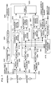
FIG. 7 is a block diagram showing the other
structure of the transmission diversity apparatus
of the present invention. In the first embodiment,
the unique word, which was the known symbol, was used
as a reference signal, and the correlation between
the receiving signal of each antenna and the
reference signal was processed, thereby estimating
desired signal power of each antenna. Then, the
antenna having the highest correlation value was
selected, and the transmitting diversity effect
could be obtained even in a case where the
interference station existed.
However, in a PHS system in which the unique
word is used in common in the desired station and
the interference station and these stations cannot
be discriminated, a correct reception cannot be
sometimes performed because of the change in a
propagation environment and the movement of the
desired station. In order to solve such a problem,
in the second embodiment, the unique word (UW1) in
the synchronous burst and the message portion (ME2)
in the communication channel are switched to each
other so as to produce the reference signal.
First, signals are received from antenna #1,
#2, and #3. The received signals are separated by
receiving/transmitting separators 301, 302, and 303
of the respective antennas, and sent to the
receiving RF sections 304, 305, and 306. The
carrier frequency signals are converted to the base
band signals by the receiving RF sections 304, 305,
and 306. Further, power levels of the respective
base band signals are controlled by AGC circuits 307,
308, and 309, and A/D converters 310, 311, and 312
convert these base band signals to digital signals.
The digital signals S1, S2, and S3 are received by
an interference removing circuit 313 having a receiving
diversity function, and decoded by a decoder
314. Thereby, a receiving message can be obtained.
On the other hand, a switching device 315
changes the unique word in the synchronous burst,
which is the known symbol, as a reference signal and
the receiving message. The unique word and the
receiving message are modulated again by a modulator
316, and input to correlation devices 317, 318, and
319.
The correlation devices 317, 318, and 319
process the correlation between the signals modulated
again and the digital signals S1, S2, and S3,
which are the outputs of the A/D converters 310, 311,
312. Standardizing devices 320, 321, and 322
standardize the outputs of the correlation devices
317, 318, and 319 with control values C1, C2, and
C3 of the AGC circuits 307, 308, and 309. Thereby,
receiving level estimation values of actual desired
waves can be obtained. A comparator 323 compares
the receiving level estimation values, and selects
a transmitting antenna, which has the maximum receiving
level estimation value of the desired wave,
and which is suitable for combating with the
interfering signal. Then, the comparator 323
outputs the selection result to a switching device
324.
On the other hand, a modulator 326 modulates
a transmitting message input from a terminal 325.
Then, the modulated transmitting message is converted
to a carrier frequency signal by a
transmitting RF section 327. The switching device
324 switches the reference signal so as to transmit
the carrier frequency signal from any one of the
selected transmitting antennas 1, 2, and 3 in
accordance with the output of the comparator 323.
The carrier frequency signal is transmitted through
receiving/transmitting separators 301, 302, and
303.
The above-explained process is basically the
same as the first embodiment. However, in the
second embodiment, a switching device 615 switches
the unique word (UW1) in the synchronous burst and
the message portion (ME2) in the communication
channel signal. Thereby, the reference signals of
the correlation devices 317, 318, and 319 are
produced.
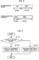
FIG. 8 is the flow chart. More specifically,
it is determined each time whether or not the
receiving signal is the synchronous burst (ST201).
When the receiving signal is the synchronous burst,
the unique word (UW1) in the synchronous burst is
used as a reference signal (ST202). When the receiving
signal is not the synchronous burst, the
message portion (UW2) in the communication channel
signal is used as a reference signal (ST203). Thus,
the switching device 315 is controlled. A
modulation signal of either one of unique words is
input to the correlation devices 317, 318, and 319.
By the use of the reference signal selected as
mentioned manner, the transmitting message can be
transmitted from the antenna having the maximum
desired signal power at the time of receiving the
synchronous burst and at the time of receiving the
communication channel.
Since the message portion of the receiving
signal is not generally the known symbol sequence,
the message portion cannot be used as a reference
signal. However, when an error rate of the message
portion is about 10-2, the number of errors in one
slot is small. For this reason, as shown in FIG.
9A, even if the interfering signal is added to the
desired signal, the number of signals, which exceed
a quadrant to the extent that the determination
error occurs, is small. In other words, if the
signal point position is known instead of the known
symbol sequence, the received signal to which the
interfering signal of the message portion is added
as shown in FIG. 9B is redetermined as being placed
at the original signal point position for each
quadrant. Thereby, the interfering signal of the
message portion can be removed. The symbol determined
in this way is considered to be substantially
correct, and is used as a reference signal.
Thus, the unique word in the synchronous burst
having a different unique word pattern and the
message portion signal in the communication channel
signal from which the interfering signal is removed
are compared with each other by use of the receiving
signals from the respective antennas. Thereby, the
transmitting antenna, which has the highest
correlation with the desired signal and which has
the maximum desired signal power, can be selected
even in a case in which there is the interference
station having the same unique word pattern as that
of the desired station. As a result, the
transmitting antenna can be correctly selected in
accordance with the movement of the desired station
and the change in the propagation environment.
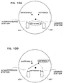
In consideration of using a nondirectional
antenna as an antenna for receiving and transmitting,
the suitable antenna is conventionally selected by
the following method. More specifically, as shown
in FIG. 10A, the antenna is selected by the sum of
the field strength of the receiving signals from a
desired station 401 and an interference station 402.
According to this method, however, an antenna
(antenna 3), in which the antenna distance between
the desired station 401 and the interference station
402 is the shortest, is selected. When the
transmission is performed using the selected antenna
3, an interference to the interference station
402 increases, and a call is cut off in the worst
case. According to the first and second embodiments
of the present invention, however, the antenna 1
having the maximum desired signal power in the
receiving signals of the desired station and the
interference station 402 is selected as a suitable
antenna as shown in FIG.10B. As a result, the
transmission can be performed using the antenna in
which the distance between the interference station
402 and the transmitting antenna is long. Therefore,
the interference to the interference station 402 is
reduced, and the frequency effective use is
possible.
In consideration of using a directional antenna
as an antenna for receiving and transmitting, as
shown in FIG. 11A, an interference to an
interference station 502 can be reduced at the
signal reception, and this leads to improvement of
the quality of the signal reception. On the other
hand, as shown in FIG. 11B, a directional antenna
having the maximum desired power of a desired
station 501 is selected at the signal transmission.
As a result, in a case where the interference station
502 is out of the directional range, the
interference to the interference station 502 due to
transmission can be greatly reduced. In this case,
since unnecessary waves are not emitted out of the
directional range, the channel capacity, excepting
a portion shown by oblique lines in FIG. 11B, can
be improved.
The transmission diversity apparatus can be
applied to a base station apparatus and a mobile
station in a radio wave communication system.
As explained above, according to the present
invention, the antenna having the maximum desired
signal power is selected, thereby making it possible
to obtain the suitable transmission diversity effect
using the antenna, which is strongest against
the interfering signal even in a case where the
interference station exists.