EP0888076B1 - Tellerförmiger deckel für kochgeschirr, gargefässe o. dgl. - Google Patents
Tellerförmiger deckel für kochgeschirr, gargefässe o. dgl. Download PDFInfo
- Publication number
- EP0888076B1 EP0888076B1 EP97906179A EP97906179A EP0888076B1 EP 0888076 B1 EP0888076 B1 EP 0888076B1 EP 97906179 A EP97906179 A EP 97906179A EP 97906179 A EP97906179 A EP 97906179A EP 0888076 B1 EP0888076 B1 EP 0888076B1
- Authority
- EP
- European Patent Office
- Prior art keywords
- lid
- lid according
- handle
- rim
- cover
- Prior art date
- Legal status (The legal status is an assumption and is not a legal conclusion. Google has not performed a legal analysis and makes no representation as to the accuracy of the status listed.)
- Expired - Lifetime
Links
- 238000010411 cooking Methods 0.000 title claims abstract description 43
- 239000011521 glass Substances 0.000 claims description 21
- 229910052751 metal Inorganic materials 0.000 claims description 13
- 239000002184 metal Substances 0.000 claims description 13
- 239000011324 bead Substances 0.000 claims description 11
- XEEYBQQBJWHFJM-UHFFFAOYSA-N Iron Chemical compound [Fe] XEEYBQQBJWHFJM-UHFFFAOYSA-N 0.000 claims description 6
- 239000000463 material Substances 0.000 claims description 4
- 229910000831 Steel Inorganic materials 0.000 claims description 3
- 239000000853 adhesive Substances 0.000 claims description 3
- 230000001070 adhesive effect Effects 0.000 claims description 3
- 229910052782 aluminium Inorganic materials 0.000 claims description 3
- XAGFODPZIPBFFR-UHFFFAOYSA-N aluminium Chemical compound [Al] XAGFODPZIPBFFR-UHFFFAOYSA-N 0.000 claims description 3
- 239000000919 ceramic Substances 0.000 claims description 3
- 239000004020 conductor Substances 0.000 claims description 3
- 229910052742 iron Inorganic materials 0.000 claims description 3
- 238000007639 printing Methods 0.000 claims description 3
- 238000005488 sandblasting Methods 0.000 claims description 3
- 239000010959 steel Substances 0.000 claims description 3
- 230000001419 dependent effect Effects 0.000 claims description 2
- 241000282472 Canis lupus familiaris Species 0.000 claims 2
- 238000009835 boiling Methods 0.000 claims 2
- 230000000717 retained effect Effects 0.000 claims 2
- 239000004411 aluminium Substances 0.000 claims 1
- 238000005034 decoration Methods 0.000 claims 1
- 229920002994 synthetic fiber Polymers 0.000 claims 1
- 238000004140 cleaning Methods 0.000 description 9
- 210000001331 nose Anatomy 0.000 description 9
- 238000000034 method Methods 0.000 description 8
- 238000004519 manufacturing process Methods 0.000 description 7
- 238000011161 development Methods 0.000 description 5
- 239000004519 grease Substances 0.000 description 5
- XLYOFNOQVPJJNP-UHFFFAOYSA-N water Chemical compound O XLYOFNOQVPJJNP-UHFFFAOYSA-N 0.000 description 5
- 208000027418 Wounds and injury Diseases 0.000 description 4
- 230000006378 damage Effects 0.000 description 4
- 208000014674 injury Diseases 0.000 description 4
- GQWNECFJGBQMBO-UHFFFAOYSA-N Molindone hydrochloride Chemical compound Cl.O=C1C=2C(CC)=C(C)NC=2CCC1CN1CCOCC1 GQWNECFJGBQMBO-UHFFFAOYSA-N 0.000 description 2
- 230000000903 blocking effect Effects 0.000 description 2
- 238000009529 body temperature measurement Methods 0.000 description 2
- 238000010276 construction Methods 0.000 description 2
- 238000011109 contamination Methods 0.000 description 2
- 238000013461 design Methods 0.000 description 2
- 239000007788 liquid Substances 0.000 description 2
- 239000004033 plastic Substances 0.000 description 2
- 238000007789 sealing Methods 0.000 description 2
- 229910000679 solder Inorganic materials 0.000 description 2
- 238000003860 storage Methods 0.000 description 2
- 241000467686 Eschscholzia lobbii Species 0.000 description 1
- -1 For example Substances 0.000 description 1
- 238000004026 adhesive bonding Methods 0.000 description 1
- 239000012080 ambient air Substances 0.000 description 1
- 238000005452 bending Methods 0.000 description 1
- 230000009286 beneficial effect Effects 0.000 description 1
- 238000002485 combustion reaction Methods 0.000 description 1
- 238000009826 distribution Methods 0.000 description 1
- 238000005553 drilling Methods 0.000 description 1
- 238000012986 modification Methods 0.000 description 1
- 230000004048 modification Effects 0.000 description 1
- 210000000056 organ Anatomy 0.000 description 1
- 230000005855 radiation Effects 0.000 description 1
- 230000000452 restraining effect Effects 0.000 description 1
- 230000000630 rising effect Effects 0.000 description 1
- 238000007788 roughening Methods 0.000 description 1
- 238000007493 shaping process Methods 0.000 description 1
- 238000012549 training Methods 0.000 description 1
- 238000012546 transfer Methods 0.000 description 1
- 238000009423 ventilation Methods 0.000 description 1
Images






Classifications
-
- A—HUMAN NECESSITIES
- A47—FURNITURE; DOMESTIC ARTICLES OR APPLIANCES; COFFEE MILLS; SPICE MILLS; SUCTION CLEANERS IN GENERAL
- A47J—KITCHEN EQUIPMENT; COFFEE MILLS; SPICE MILLS; APPARATUS FOR MAKING BEVERAGES
- A47J36/00—Parts, details or accessories of cooking-vessels
- A47J36/06—Lids or covers for cooking-vessels
- A47J36/064—Lids or covers for cooking-vessels non-integrated lids or covers specially adapted for frying-pans
-
- A—HUMAN NECESSITIES
- A47—FURNITURE; DOMESTIC ARTICLES OR APPLIANCES; COFFEE MILLS; SPICE MILLS; SUCTION CLEANERS IN GENERAL
- A47J—KITCHEN EQUIPMENT; COFFEE MILLS; SPICE MILLS; APPARATUS FOR MAKING BEVERAGES
- A47J45/00—Devices for fastening or gripping kitchen utensils or crockery
- A47J45/06—Handles for hollow-ware articles
- A47J45/07—Handles for hollow-ware articles of detachable type
- A47J45/072—Bowl handles
-
- Y—GENERAL TAGGING OF NEW TECHNOLOGICAL DEVELOPMENTS; GENERAL TAGGING OF CROSS-SECTIONAL TECHNOLOGIES SPANNING OVER SEVERAL SECTIONS OF THE IPC; TECHNICAL SUBJECTS COVERED BY FORMER USPC CROSS-REFERENCE ART COLLECTIONS [XRACs] AND DIGESTS
- Y10—TECHNICAL SUBJECTS COVERED BY FORMER USPC
- Y10S—TECHNICAL SUBJECTS COVERED BY FORMER USPC CROSS-REFERENCE ART COLLECTIONS [XRACs] AND DIGESTS
- Y10S220/00—Receptacles
- Y10S220/912—Cookware, i.e. pots and pans
Definitions
- the invention relates to a plate-shaped cover for Cookware, cooking vessels or the like, such as a saucepan or frying pan, at least one in a central central area Has opening, wherein, preferably on the top of the lid,> a roof-like at least one opening overlapping cover element held by a bracket is.
- this lid has a cover element, which is a complete or partial closure of the Breakthrough allowed.
- the cover element is optionally available as Attachment or plug-in element can be used and has one button-shaped handle. Due to the special arrangement of Edge cams on the cover element and projections on the edge of the Opening there is the possibility of the cover element either to put on the projections with the edge cams, so that ventilation of the cookware during the cooking process is possible.
- the cover element can also be in a position rotated by approximately 45 ° with respect to the first position fully inserted into the opening so that a The cooking vessel is not ventilated. With this well-known cover element can thus either completely or partially closed.
- the lid knob a handle has, which by means of a fastening element with a Blocking member is connected. Between the handle and the lid a rosette is arranged. There is still one in the grip part Recording designed for the fastener.
- the Locking device is provided with a sealing and support surface which rests the grip part, the grip part and locking process are arranged rotatably to each other.
- the blocking organ is with one or more radially arranged channels provided are connected via openings of the fastening element.
- the locking member is in a tightly enclosing this Recess of the rosette arranged on its circumference with the Provide channels releasing and closing elements.
- the rosette can be released or closed by twisting it adjustable.
- This training with a lid button Controllable steam outlet is technically difficult to manufacture and extremely difficult to clean.
- the special Arrangement of the channels of the steam emerging from the cooking vessel be derived to the lid surface, however especially in case of carelessness of the user burns, For example, the user's hand, not easily to exclude.
- a frying pan lid known, which consists of metal and a central, circular Has opening, which should serve the removal of water vapor. Above this opening is an inward and to the center the opening curved shielding element is arranged, which on Edge extends a certain amount beyond the opening.
- the Shielding element is on the with some narrow supports Lid attached.
- the advantage of this frying pan lid is said to be consist of contamination of the cooker or lid by splashing around oil, fat or the like during the Frying process is largely avoided because of that Shielding oil, grease splashes or the like due to the curvature of the shielding element on its underside towards the center of the shielding element flow back and from there through the Drip the opening back into the frying pan.
- the invention is based on the object To create lids with improved handling. Especially the lid should be simple while using the cookware and can be safely removed from or placed on the cookware be attachable. After using the lid you should look for one ancillary aspect of the invention may be a light and safe cleaning of the lid are made possible.
- This task is performed with a lid of the type mentioned solved according to the invention in that the bracket as the lid is designed in the manner of a bracket-spanning handle part and the end portions of the handle part on the lid edge are attached. Because the bracket the cover total i. w. diametrically spanned, the user can Lids for the purpose of taking them off or putting them on Grab areas where hot spills occur Water vapor or the like is not to be expected. A possible danger the combustion is thus largely reduced.
- the invention without further ado the possibility of this as a holder trained handle part of the lid for the purpose of cleaning to solve, so that an easy and quick cleaning of the Cover and the cover element is guaranteed.
- the lid according to the invention also has no sharp edges Parts or the like on, so that a risk of injury during the Cleaning process is practically impossible.
- the edge of the lid by an upwardly curved ring wall formed, the ring wall pointing radially outwards, Has tabs, cams or the like.
- the on the periphery of the lid circumferential ring wall reliably prevents fat from flowing off, Vapors, oil or the like, which is caused by the opening in the cover has stepped outside.
- this ring wall offers the prerequisite for making the handle part simple and safe can be placed on the edge of the lid.
- the radially outward Pointing lugs on the edge of the lid serve the simple Attachment of the handle part to the lid.
- the end sections of the Handle parts thus have pocket-shaped receptacles, the lugs of the lid in the fastening position reach around.
- the handle part placed on the lid the groove or groove-like Recordings of the end portions of the handle part laterally the lugs on the upwardly curved ring wall of the lid sit on.
- a locking element a slide or the like. pivotable, tiltable or the like. With which the Handle part on the lid can be secured against accidental loosening is.
- the locking element is advantageous in this area a second side edge of the handle part and has a stop, especially a tongue, nose, tab o. Like., In the locking position to the side of the nose of Cover is applied. Through these measures, the first open pocket on one side to hold the nose of the lid the locking element located in the locking position closed, so that accidental loosening of the handle part is excluded from the lid.
- Locking element in particular with a bolt or the like in particular transverse to the longitudinal extent of the handle part is arranged in the region of the end section of the Handle part swiveling, tiltable or the like.
- This measure is characterized by a structurally extremely simple and thus also inexpensive construction.
- the top of the lid i. w. concave.
- the lid is made of glass, ceramic, plastic and / or metal or the like, the underside of the cover possibly by sandblasting, printing, attaching knobs or one the decor is roughened. This measure leaves one Observation of the food in the cookware, cooking vessel or the like. despite the lid on. On the other hand, one worries Roughening the bottom of the lid for improved Non-slip when the lid is placed on the cooking pan is. Accidental slipping of the lid from the There is no need to worry about cookware.
- the handle part has a central part for attachment or Holder of the cover on which middle part extend two, possibly three or more arms to the edge of the lid. This creates a particularly stable grip part, which can be easily and securely attached to the lid.
- the arms of the handle part point diametrically outwards so that the handle part along the lid of a diameter spanned in a bow-shaped or bridge-like manner.
- the arms of the handle part point diametrically outwards so that the handle part along the lid of a diameter spanned in a bow-shaped or bridge-like manner.
- it can also be indicated three, four or more arms to be provided for the handle part in the area of the middle part converge and preferably the same angle between include neighboring arms.
- a three-armed Grip parts are preferably adjacent arms with an angle of 120 °, preferably four at an angle of 90 ° etc. arranged.
- the handle part Adjustment device for preferably stepless lowering or Lift the cover element to or from the cover.
- the lid depending on the individual needs with regard to the cooking or cooking process to close completely or to open more or less.
- the possibility of starting a cooking or Cooking process to open the opening to the in the In the initial phase liquid escaping from the food to be cooked increases to let out while, for example, at the end of the cooking process Breakthrough completely or by means of the cover element at least in part can be closed.
- the opening may be closed, this is at the discretion of the respective user.
- the handle part has a particularly simple design for lowering / raising the cover element in a central part a bore with an internal thread in which a Adjusting element rotatably guided and on which the cover element is attached.
- the adjusting element is pot-shaped or has a central hole, the edge of the adjusting element is optionally provided with crossbars or the like, so that also at any fat or on the adjusting element Oil splashes or the like. A rotation of the adjusting element is easily possible for the user.
- thermometer arrange with which the cooking or cooking temperature in the Cooking or cooking vessel, which is covered with the lid, can be displayed.
- a releasable connecting element in particular a screw, a bolt or the like.
- the connecting element consists of thermally conductive Material such as iron, aluminum, steel or the like and is with the Thermometer thermally connected. Because that Connecting element penetrates the cover element at one end and at the other thermally conductive in connection with the thermometer stands for a precise temperature measurement in the cooking vessel or cooking pot prevailing cooking or cooking temperature. Even with the cover element raised and thus open Opening the lid is one end of the Connection element directly above the food and is over the heat radiation or the rising water vapor on the temperature prevailing in the cooking vessel itself, so that too in this case a very precise temperature measurement is guaranteed.
- the cover element i. w. formed as a circular plate or the like.
- the production of the Cover element is thus inexpensive, with the outer, after top or bottom edge of the cover element in particular bead-like, e.g. by flanging or similar measures, can be trained.
- outer edge with a plastic material or the like encapsulate.
- the measure proves to be particularly advantageous, at least that to form the outer edge region of the cover element flexibly or made of flexible material, which makes the Sealing function is further improved.
- the Cover element a central, i. w. circular protuberance on, which dips into a receptacle of the adjusting element. Consequently is the cover with respect to the positioning relative to the Adjustment element secured positively, the Connection element then only to determine the Cover element is used on the adjusting element.
- a thermostat or the like is arranged, which for a automatic, temperature-dependent raising and lowering of the Cover element is formed with respect to the opening.
- the invention on a preferably outer edge area on the Bottom of the lid one or more concentric Ring beads or ring bead sections or the like arranged or molded.
- the positioning of this, a slipping of the Lid-holding elements on the underside of the lid is chosen so that the lid on different cooking vessels is securely attachable in standard sizes.
- Embodiment of the invention also the possibility of Improving the fit of the lid on the cooking pan on the Bottom of the lid one or more circumferential rings Arrange or form steps, paragraphs or the like.
- a particularly inexpensive embodiment of the invention is that the lid of a glass shelf with a centric opening is formed and the handle part Sheet metal or the like., End sections of the Handle part attached to the lid edge by means of bends are. Since in this embodiment no cams or the like on Edge of the glass cover are to be provided, the Possibility to manufacture the glass lid extremely inexpensively.
- the lid from a glass bottom with a central opening formed, the glass bottom circumferentially by an outer ring consisting of sheet metal or the like is included and the handle part is integrally connected to the outer ring.
- the Outer ring in particular an upwardly drawn edge or the like. exhibit. This will reduce costs at Production of the lid achieved because the glass bottom itself does not have to have the edge drawn upwards.
- the one-piece connection between the handle part and the sheet metal part ensures a further reduction in production costs this embodiment of the lid according to the invention.
- a secure and permanent fixation of the outer ring or Handle part on the glass bottom is that the glass bottom a ring shoe, preferably made of sheet metal, on the edge.
- Profile possibly with a molded web, which Profile via a connection, for example a screw, rivet, adhesive or Solder connection or the like.
- the handle part four i. w. has arms arranged at right angles to one another, which extends radially outwards from a central part to the edge of the lid extend and preferably by means of end bending on Lids are attached. This measure makes a special one stable handle part created.
- Embodiment of the invention has the handle part two, the lid radially spanning, adjacent stirrups.
- the articulated arrangement advantageously has an articulated arm on the on the slide and on a storage of the Cover element is articulated.
- the at least one Opening 12 is arranged centrally and has one circular cross section. Of course there can be two or several openings in the central central region 10 be provided.
- On the top 14 of the lid 1 is a the at least one opening 12 i. w. roof-like or the like overlapping cover element 7 arranged and by means of a Bracket 16 held.
- the holder 16 is bow-shaped as the cover 1 spanning handle part 2 formed.
- the end Sections 18 of the handle part 2 are detachable on the lid edge 20 attached.
- the lid edge 20 is an upwardly curved ring wall 22 formed, this ring wall 22 in the embodiment two diametrically arranged, outwardly pointing lugs 24, Has tabs, cams or the like.
- the handle part 2 can also have more than two lugs 24 be arranged on the annular wall 22.
- the end portions 18 of the handle part 2 have on the Bottom 26 a groove or groove-like receptacle 28, in which the ring wall 22 when placed on the lid 1 Handle part 2 engages. Furthermore, the ends are Sections 18 of the handle part 2 on the underside 26 i. w. With U-shaped, hook-shaped or the like. Shaped, inside facing bends 30 provided. These bends 30 reach under or embrace the lugs 24, tabs, cams o. Like. The ring wall 22, provided that the handle part 2 on the lid. 1 is attached.
- At least one, preferably each of the bends 30 instruct a stop 34 in a first side edge 32 of the grip part 2 on, which can be designed in particular as a transverse wall.
- at least one, but preferably on several or all sections 18 of the handle part 2 one locking element 3 each pivotable, tiltable or the like. with which the handle part 2 on the lid edge 20 against ' accidental loosening can be secured.
- the locking element 3 is with a bolt 4 or the like in particular transverse to the longitudinal extent of the handle part 2 is arranged on the end portion 18 of the handle part 2 swiveling, tilting or the like.
- the locking element 3 In the closed position is the locking element 3 of a corresponding adapted recess 40 of the end portion 18 i. w. completely absorbed.
- the locking element 3 in the closed position by means of a latch or the like. lockable and against accidental transfer into the Open position secured.
- the top 14 of the lid 1 is i. w. concave educated.
- the cover 1 is made of glass, ceramic or. Like., The underside 42 of the lid 1, if necessary Sandblasting, printing, applying knobs or a decor is roughened.
- the handle part 2 has a central part 44 for attachment and / or holding the cover element 7, which differs from the Middle part 44 in the exemplary embodiment two, possibly also three or extend more arms 46 to the lid edge 20.
- the arms 46 of the Handle parts 2 have according to the preferred embodiment diametrically outward, but can also in particular in the Attachment of more than two arms 46 i. w. same angle enclose between adjacent arms 46. That angle is approx. 120 ° for three arms, approx. 90 ° for four arms etc.
- For stepless lowering / raising of the Cover element 7 to or from the cover 1 has a handle part Adjustment device 5.
- the middle part 44 of the Handle part 2 has a bore 48 with an internal thread 50 provided, in which an adjusting element 52 is rotatably guided and to which the cover element 7 is attached.
- the Adjustment element 52 itself is pot-shaped or has a hole and is possibly with crosspieces 54 or the like. provided, the transverse webs 54 on an edge 56 of the Adjustment element 52 are arranged.
- a thermometer 6 recorded with which in the cooking or cooking vessel Cooking or cooking temperature can be displayed.
- the adjusting element 52 and the cover element 7 are by means of a releasable connecting element 8, in particular one Screw, a bolt or the like. Connected together.
- the Connection element 8 consists of thermally conductive material, For example, iron, aluminum or steel and is with the thermometer 6 thermally connected.
- the cover element 7 is designed as a circular plate 60 or the like and has an edge bead.
- the surface 62 of the Cover element 7 has a convex curvature. At least that outer edge 64 of the cover element 7 is flexible or is made of flexible material.
- the Cover element 7 a central, i. w. circular protuberance 66, which in a receptacle 68 of the adjusting element 52nd immersed.
- the handle part 2 is for attachment to the lid 1 corresponding to the side of Figure 5 adjacent of the lugs 24 of the cover 1, the annular wall 22nd of the cover 1 in the receptacles 28 of the end sections 18 of the handle part 2 dips so that the handle part on the Ring wall 22 of the lid 1 is rotatably guided.
- the rotary movement of the handle part 2 with respect to the cover 1 for the connection is made by limited the stop 34 on the bends 30.
- Locking elements 3 To a unintentional detachment of the grip part 2 from the cover 1 prevent the locking elements 3 in the Transferred to the closed position, one in the Locking elements 3 provided stop 38 laterally the nose 24 of the lid 2 creates. In this closed position Locking elements 3 is thus a twisting of the handle part 2 prevented with respect to the lid.
- the cover element 7 steplessly lowered to the top 14 of the cover 1 or from this top 14 are lifted off.
- the adjusting element 52 itself is in a recess 58 or a bore Thermometer 6 arranged, which via the connecting element 8th is thermally coupled to the interior of the cooking vessel. Furthermore, the connecting element 8 serves to determine the Cover element 7 on the adjusting element 52.
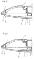
- FIGS. 12, 13 and 14 Further modifications and special embodiments of the covers according to the invention are in FIGS. 12, 13 and 14 shown, a on the underside 42 of the lid 1 Ring bead 70, an annular circumferential step 72 or a Heel or several such beads or stages 72, 74 and 76 are provided. These ring beads or gradations or Heels are on the underside 42 of the cover 1 positioned or dimensioned in their diameter that they rest as an abutment on the edge of the cooking vessels that standardized or standardized dimensions or diameter exhibit.
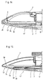
- the cover is 1 from a glass bottom with a central opening 12 formed and the handle part 2 is made of sheet metal or the like. While in the exemplary embodiment in FIG. 16, end sections 18 of the handle part 2 by means of bends 84 on the lid edge 20 are attached, is in the embodiment of Figure 15 the glass bottom is circumferentially surrounded by an outer ring 78. In Otherwise, both cases can be on the outer edge of the glass shelf provided cams or the like are omitted. Furthermore, the Embodiment of Figure 15 also an example up drawn edge 20 are eliminated, since this edge through the outer ring 78 is formed.
- the glass bottom preferably a sheet metal edge existing ring shoe 82 or the like profile, possibly with a molded web, the profile having a Connection 80, for example a screw, rivet, adhesive or Solder connection or the like is connected to the outer ring 78.
- a connection 80 for example a screw, rivet, adhesive or Solder connection or the like is connected to the outer ring 78.
- a comparable one Connection between the outer edge of the glass bottom and a Provide edge portion of the handle part 2.
- Figures 17, 18 stands out characterized in that the handle part 4 i. w. perpendicular to each other has arranged arms 46 which extend from a central part 44 extend radially outward to the lid edge 20 and preferred are attached to the cover 1 by means of end bends 84.
- FIG. 19 Another preferred embodiment of the invention exists in that the handle part 2 of two, the lid 1 radially spanning brackets 86, 88 arranged adjacent, as shown in Figures 19, 20.
- brackets 86, 88 arranged adjacent, as shown in Figures 19, 20.
- the end portions of the adjacent bracket 86, 88 each in a bracket 90, 92 held, the lid edge 20 according to Art of a U-profile and especially clamped, latching o. Like.
- brackets 90, 92 by gluing or the like. Attach method to cover 1.
- a slide 94, 96 can be moved on each bracket 86, 88 performed, being between the slides 94, 96 and the Cover element 7 a hinge arrangement for lifting or lowering of the cover element 7 is arranged.
- the joint arrangement has each have an articulated arm 98, 100 on the slide 94, 96 and a bearing 102 of the cover element 7 is articulated.
- the Sliders 94, 96 are jamming, latching or the like to the Brackets 86, 88 can be fixed. By moving the slider 94, 96 along the brackets 86, 88 can thus cover element 7 lifted from the opening 12 or onto this opening 12 can be lowered.
- This alternative construction to Actuation of the cover member 7 compared to that previously described embodiment an extreme inexpensive alternative.
Landscapes
- Engineering & Computer Science (AREA)
- Food Science & Technology (AREA)
- Cookers (AREA)
- Table Devices Or Equipment (AREA)
Description
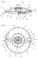
- Figur 1
- eine isometrische Ansicht eines Ausführungsbeispiels des erfindungsgemäßen Deckels mit in Schließstellung befindlichen Verriegelungselementen,
- Figur 2
- eine Seitenansicht des Deckels der Figur 1, teilweise geschnitten,
- Figur 3
- eine Draufsicht des Deckels der Figur 1,
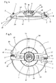
- Figur 4
- eine Seitenansicht des Deckels der Figur 1 jedoch mit geöffneten Verriegelungselementen,
- Figur 5
- eine Draufsicht des Deckels der Figur 4,
- Figur 6
- einen Querschnitt durch den Deckel entlang der Schnittlinie A-A der Figur 3,
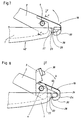
- Figur 7
- eine Detailseitenansicht gemäß Ausschnitt B der Figur 2,
- Figur 8
- eine Detailseitenansicht gemäß Ausschnitt C der Figur 4,
- Figur 9
- eine Draufsicht der Detaildarstellung in Richtung D der Figur 8,
- Figur 10
- eine Draufsicht der Detaildarstellung der Figur 7 in Richtung E,
- Figur 11
- einen Schnitt entlang der Schnittlinie F-F der Figur 7,
- Figur 12
- eine Teilschnittdarstellung einer weiteren Ausführungsform der Erfindung mit einem Ringwulst auf der Unterseite des Deckels,
- Figur 13
- eine Teilschnittdarstellung eines weiteren Ausführungsbeispiels der Erfindung mit einer ringförmig umlaufenden Stufe an der Unterseite des Deckels,
- Figur 14
- eine Teilschnittdarstellung eines weiteren Ausführungsbeispiels der Erfindung mit einer Mehrzahl von ringförmig umlaufenden Stufen an der Unterseite des Deckels,
- Figur 15
- eine Teilschnittdarstellung eines weiteren Ausführungsbeispiels der Erfindung, bei dem der Deckel aus einem Glasboden und einem Außenring besteht,
- Figur 16
- eine Teilschnittdarstellung einer weiteren Ausführungsform der Erfindung, bei der das insbesondere aus Blech bestehende Griffteil mittels einer Umbiegung am Deckelrand befestigt ist,
- Figur 17
- eine Draufsicht auf ein weiteres Ausführungsbeispiel der Erfindung mit einem aus vier Armen bestehenden Griffteil,
- Figur 18
- eine Schnittdarstellung des Ausführungsbeispiels der Figur 17 entlang der Schnittlinie A-A,
- Figur 19
- eine Draufsicht auf eine weitere Ausführungsform des Deckels mit einer modifizierten Verstelleinrichtung für das Abdeckelement und
- Figur 20
- eine Seitenansicht, teilweise geschnitten des Ausführungsbeispiels der Figur 19.
- 1
- - Deckel
- 2
- - Griffteil
- 3
- - Verriegelungselement
- 4
- - Bolzen
- 5
- - Verstelleinrichtung
- 6
- - Thermometer
- 7
- - Abdeckelement
- 8
- - Verbindungselement
- 10
- - Mittelbereich
- 12
- - Durchbrechung
- 14
- - Oberseite
- 16
- - Halterung
- 18
- - endseitiger Abschnitt
- 20
- - Deckelrand
- 22
- - Ringwand
- 24
- - Nase
- 26
- - Unterseite
- 28
- - Aufnahme
- 30
- - Umbiegung
- 32
- - erster Seitenrand
- 34
- - Anschlag
- 36
- - zweiter Seitenrand
- 38
- - Anschlag
- 40
- - Ausnehmung
- 42
- - Unterseite
- 44
- - Mittelteil
- 46
- - Arm
- 48
- - Bohrung
- 50
- - Innengewinde
- 52
- - Verstellelement
- 54
- - Quersteg
- 56
- - Rand
- 58
- - Ausnehmung
- 60
- - Kreisplatte
- 62
- - Oberfläche
- 64
- - äußerer Rand
- 66
- - Ausstülpung
- 68
- - Aufnahme
- 70
- - Ringwulst
- 72
- - Stufe, Absatz
- 74
- - Stufe, Absatz
- 76
- - Stufe, Absatz
- 78
- - Außenring
- 80
- - Verbindung
- 82
- - Ringschuh, U-Profil
- 84
- - Umbiegung
- 86
- - Bügel
- 88
- - Bügel
- 90
- - Halterung
- 92
- - Halterung
- 94
- - Schieber
- 96
- - Schieber
- 98
- - Gelenkarm
- 100
- - Gelenkarm
- 102
- - Lagerung
Claims (37)
- Tellerförmiger Deckel (1) für Kochgeschirr, Gargefäße o. dgl., wie Kochtopf oder Bratpfanne, der in einem zentralen Mittelbereich (10) wenigstens eine Durchbrechung (12) aufweist, wobei, vorzugsweise auf der Oberseite (14) des Deckels (1), ein die wenigstens eine Durchbrechung (12) dachartig übergreifendes Abdeckelement (7) mittels einer Halterung (16) gehaltert ist, dadurch gekennzeichnet, daß die Halterung (16) als den Deckel (1) bügelartig überspannendes Griffteil (2) ausgebildet ist und die endseitigen Abschnitte (18) des Griffteils (2) an dem Deckelrand (20) befestigt sind.
- Deckel nach Anspruch 1, dadurch gekennzeichnet, daß das Griffteil (2) lösbar an dem Deckelrand (20) befestigt ist.
- Deckel nach einem der vorhergehenden Ansprüche, dadurch gekennzeichnet, daß der Deckelrand (20) durch eine nach oben gebogene Ringwand (22) gebildet ist, wobei die Ringwand (22) radial nach außen weisende Nasen (24), Laschen, Nocken o. dgl. aufweist.
- Deckel nach Anspruch 3, dadurch gekennzeichnet, daß die endseitigen Abschnitte (18) des Griffteils (2) an der Unterseite (26) eine nut- oder rinnenartige Aufnahme für die Ringwand (22) aufweisen.
- Deckel nach einem der vorhergehenden Ansprüche 3 oder 4, dadurch gekennzeichnet, daß die endseitigen Abschnitte (18) des Griffteils (2) an der Unterseite (26) eine i. w. U-förmige, hakenförmige o. dgl. geformte, nach innen weisende Umbiegung (30) besitzen, mit welcher Umbiegung (30) die Nase (24), Lasche, der Nocken o. dgl. umgreifbar, untergreifbar bzw. hintergreifbar ist.
- Deckel nach Anspruch 5, dadurch gekennzeichnet, daß die Umbiegung (30) an einem ersten Seitenrand (32) des Griffteils (2) einen Anschlag (34), insbesondere eine Querwand o. dgl. aufweist.
- Deckel nach einem der vorhergehenden Ansprüche, dadurch gekennzeichnet, daß an wenigstens einem endseitigen Abschnitt (18) des Griffteils (2) ein Verriegelungselement (3), ein Schieber o. dgl. schwenkbar, kippbar o. dgl. gelagert ist, mit dem das Griffteil (2) am Deckelrand (20) gegen versehentliches Lösen sicherbar ist.
- Deckel nach Anspruch 7, dadurch gekennzeichnet, daß das Verriegelungselement (3) im Bereich eines zweiten Seitenrandes (36) des Griffteils (2) angeordnet ist und einen Anschlag (38), insbesondere eine Zunge, Nase, Lasche o. dgl. aufweist, die in der Verriegelungsstellung seitlich der Nase (24) des Deckels (2) anliegt.
- Deckel nach einem der Ansprüche 7 oder 8, dadurch gekennzeichnet, daß das Verriegelungselement (3) insbesondere mit einem Bolzen (4) o. dgl., der insbesondere quer zur Längserstreckung des Griffteils bzw. eines Arms (46) des Griffteils (2) angeordnet ist, im Bereich eines endseitigen Abschnitts des Griffteils (2) schwenkbar, kippbar o. dgl. gelagert ist.
- Deckel nach einem der Ansprüche 7 bis 9, dadurch gekennzeichnet, daß das Verriegelungselement (3) in der Schließstellung von einer entsprechend angepaßten Ausnehmung (40) des endseitigen Abschnitts (18) i. w. vollständig aufgenommen ist.
- Deckel nach einem der Ansprüche 7 bis 10, dadurch gekennzeichnet, daß das Verriegelungselement (3) in der Schließstellung mittels einer Rastnase o. dgl. verrastbar ist.
- Deckel nach einem der vorhergehenden Ansprüche, dadurch gekennzeichnet, daß die Oberseite (14) des Deckels (1) i. w. konkav gewölbt ausgebildet ist.
- Deckel nach einem der vorhergehenden Ansprüche, dadurch gekennzeichnet, daß der Deckel (1) aus Glas, Keramik, Kunststoff und/oder Metall o. dgl. besteht, wobei die Unterseite (42) des Deckels (1) ggf. durch Sandstrahlen, Bedrucken, Anbringung von Noppen oder eines Dekors aufgerauht ist.
- Deckel nach einem der vorhergehenden Ansprüche, dadurch gekennzeichnet, daß das Griffteil (2) ein Mittelteil (44) zur Anbringung und/oder Halterung des Abdeckelements (7) aufweist, von welchem Mittelteil (44) sich zwei, ggf. auch drei oder mehr Arme (46) zum Deckelrand (20) erstrecken.
- Deckel nach Anspruch 14, dadurch gekennzeichnet, daß die Arme (46) des Griffteils (2) diametral nach außen weisend oder i. w. gleiche Winkel zwischen benachbarten Armen (46) einschließend, angeordnet sind.
- Deckel nach einem der vorhergehenden Ansprüche, dadurch gekennzeichnet, daß das Griffteil (2) eine Verstelleinrichtung (5) zum vorzugsweise stufenlosen Absenken bzw. Anheben des Abdeckelements (7) zum bzw. vom Deckel (1) aufweist.
- Deckel nach Anspruch 16, dadurch gekennzeichnet, daß das Griffteil (2) in einem Mittelteil (44) eine Bohrung (48) mit einem Innengewinde (50) aufweist, in der ein Verstellelement (52) verdrehbar geführt und an der das Abdeckelement (7) befestigt ist.
- Deckel nach Anspruch 16 oder 17, dadurch gekennzeichnet, daß das Verstellelement (52) topfartig ausgebildet ist oder eine Bohrung aufweist und ggf. einen mit Querstegen (54) o. dgl. versehen Rand (56) besitzt.
- Deckel nach einem der Ansprüche 16 bis 18, dadurch gekennzeichnet, daß in einer Ausnehmung (58) oder Bohrung des Verstellelements (52) ein Thermometer (6) aufgenommen ist zur Anzeige der Gar- oder Kochtemperatur in dem Gar- oder Kochgefäß, welches mit dem Deckel (1) beaufschlagt ist.
- Deckel nach einem der Ansprüche 16 bis 19, dadurch gekennzeichnet, daß das Verstellelement (52) und das Abdeckelement (7) mittels eines lösbaren Verbindungselements (8), insbesondere Schraube, Bolzen o. dgl., miteinander verbunden sind.
- Deckel nach Anspruch 20, dadurch gekennzeichnet, daß das Verbindungselement (8) aus wärmeleitfähigem Material, wie Eisen, Aluminium, Stahl o. dgl. besteht und mit dem Thermometer (6) wärmeleitend verbunden bzw. gekoppelt ist.
- Deckel nach einem der vorhergehenden Ansprüche, dadurch gekennzeichnet, daß das Abdeckelement (7) i. w. als Kreisplatte (60) ausgebildet ist und bevorzugt einen randseitigen nach oben oder unten gerichteten Wulst o. dgl. aufweist.
- Deckel nach einem der vorhergehenden Ansprüche, dadurch gekennzeichnet, daß die Oberfläche des Abdeckelements (7) konvex gewölbt ausgebildet ist.
- Deckel nach einem der vorhergehenden Ansprüche, dadurch gekennzeichnet, daß zumindest der äußere Rand (64) des Abdeckelements (7) flexibel ist oder aus flexiblem Material besteht.
- Deckel nach einem der vorhergehenden Ansprüche, dadurch gekennzeichnet, daß das Abdeckelement (7) eine zentrale, i. w. kreisförmige Ausstülpung (66) aufweist, die in eine Aufnahme (68) des Verstellelements (52) eintaucht.
- Deckel nach einem der vorhergehenden Ansprüche, dadurch gekennzeichnet, daß in einer Ausnehmung (58) des Verstellelements (52) ein Thermostat o. dgl. angeordnet ist, welcher für ein selbsttätiges, temperaturabhängiges Anheben und Absenken des Abdeckelements (7) bzgl. der Durchbrechung (1) ausgebildet ist.
- Deckel nach einem der vorhergehenden Ansprüche, dadurch gekennzeichnet, daß in einem bevorzugt äußeren Randbereich an der Unterseite (42) des Deckels (1) ein oder mehrere konzentrische Ringwülste (70) oder Ringwulstabschnitte o. dgl. angeordnet bzw. angeformt sind.
- Deckel nach einem der Ansprüche 1 bis 26, dadurch gekennzeichnet, daß in einem bevorzugt äußeren Randbereich an der Unterseite (42) des Deckels (1) ein oder mehrere ringförmig umlaufende Stufen (72, 74, 76), Absätze o. dgl. angeordnet bzw. angeformt sind.
- Deckel nach einem der Ansprüche 1 bis 3, 12 bis 28, dadurch gekennzeichnet, daß der Deckel (1) von einem Glasboden mit einer zentrischen Durchbrechung (12) gebildet ist und das Griffteil (2) aus Blech o. dgl. besteht, wobei endseitige Abschnitte (18) des Griffteils (2) mittels Umbiegungen (84) an dem Deckelrand (20) befestigt sind.
- Deckel nach einem der Ansprüche 1 bis 3, 12 bis 28, dadurch gekennzeichnet, daß der Deckel (1) von einem Glasboden mit einer zentrischen Durchbrechung (12) gebildet ist, wobei der Glasboden umfangsseitig von einem Außenring (78) bestehend aus Blech o. dgl. umfaßt ist und das Griffteil (2) einstückig mit dem Außenring (78) verbunden ist.
- Deckel nach Anspruch 29 oder 30, dadurch gekennzeichnet, daß der Glasboden randseitig einen bevorzugt aus Blech bestehenden Ringschuh (82) o. dgl. Profil, ggf. mit einem angeformten Steg, aufweist, welches Profil über eine Verbindung (80), bspw. einer Schraub-, Niet-, Klebe- oder Lötverbindung o. dgl. mit dem Griffteil (2) bzw. dem Außenring (78) verbunden ist.
- Deckel nach einem der Ansprüche 1 bis 3, 12 bis 28, dadurch gekennzeichnet, daß das Griffteil (2) vier i. w. rechtwinklig zueinander angeordnete Arme (46) aufweist, die sich von einem Mittelteil (44) radial nach außen zum Deckelrand (20) erstrecken und bevorzugt mittels endseitiger Umbiegungen (84) am Deckel (1)befestigt sind.
- Deckel nach einem der Ansprüche 1 bis 3, 12 bis 16, 22 bis 28, dadurch gekennzeichnet, daß das Griffteil (2) aus zwei, den Deckel (1) radial überspannende, benachbart angeordneten Bügeln (86, 88) besteht.
- Deckel nach Anspruch 33, dadurch gekennzeichnet, daß die endseitigen Abschnitte der benachbarten Bügel (86, 88) jeweils in einer Halterung (90, 92) gehalten sind, die den Deckelrand (20) nach Art eines U-Profils umgreifen und insbesondere klemmend, rastend o. dgl. am Deckel (1) festgelegt sind.
- Deckel nach einem der Ansprüche 33 oder 34, dadurch gekennzeichnet, daß auf jedem Bügel (86, 88) ein Schieber (94, 96) verschiebbar geführt ist, wobei zwischen den Schiebern (94, 96) und dem Abdeckelement (7) eine Gelenkanordnung zum Abheben bzw. Absenken des Abdeckelements (7) angeordnet ist.
- Deckel nach Anspruch 35, dadurch gekennzeichnet, daß die Gelenkanordnung jeweils einen Gelenkarm (98, 100) aufweist, der an dem Schieber (94, 96) und an einer Lagerung (102) des Abdeckelements (7) angelenkt ist.
- Deckel nach einem Ansprüche 35 bis 36, dadurch gekennzeichnet, daß die Schieber (94, 96) an den Bügeln (86, 88) klemmend, rastend o. dgl. festlegbar sind.
Applications Claiming Priority (3)
| Application Number | Priority Date | Filing Date | Title |
|---|---|---|---|
| DE19611310A DE19611310C2 (de) | 1996-03-22 | 1996-03-22 | Tellerförmiger Deckel für Kochgeschirr, Gargefäße o. dgl. |
| DE19611310 | 1996-03-22 | ||
| PCT/EP1997/001131 WO1997035504A1 (de) | 1996-03-22 | 1997-03-06 | Tellerförmiger deckel für kochgeschirr, gargefässe o. dgl. |
Publications (2)
| Publication Number | Publication Date |
|---|---|
| EP0888076A1 EP0888076A1 (de) | 1999-01-07 |
| EP0888076B1 true EP0888076B1 (de) | 1999-09-22 |
Family
ID=7789077
Family Applications (1)
| Application Number | Title | Priority Date | Filing Date |
|---|---|---|---|
| EP97906179A Expired - Lifetime EP0888076B1 (de) | 1996-03-22 | 1997-03-06 | Tellerförmiger deckel für kochgeschirr, gargefässe o. dgl. |
Country Status (8)
| Country | Link |
|---|---|
| US (1) | US6129234A (de) |
| EP (1) | EP0888076B1 (de) |
| AT (1) | ATE184770T1 (de) |
| AU (1) | AU2095897A (de) |
| DE (2) | DE19611310C2 (de) |
| ES (1) | ES2138861T3 (de) |
| FR (1) | FR2746287B3 (de) |
| WO (1) | WO1997035504A1 (de) |
Families Citing this family (37)
| Publication number | Priority date | Publication date | Assignee | Title |
|---|---|---|---|---|
| US7571675B1 (en) * | 1999-10-22 | 2009-08-11 | Carico International, Inc. | Lid for cooking pan |
| CA2455023A1 (en) * | 2003-01-09 | 2004-07-09 | Wki Holding Company, Inc. | Cooking vessels and lid therefor |
| ITRM20040209A1 (it) * | 2004-04-30 | 2004-07-30 | Opinion Leaders S R L | Coperchio perfezionato per contenitori per la cottura di cibi. |
| USD539604S1 (en) * | 2005-06-09 | 2007-04-03 | Eddie Man-Ying Chan | Cover for cooking utensil |
| ITMO20050189A1 (it) * | 2005-07-21 | 2007-01-22 | Gaetano Mancini | Coperchio universale per pentole con recupero condensa |
| CH698173B1 (de) * | 2005-11-08 | 2009-06-15 | Belcap Switzerland Ag | Behälter-Verschluss zum gleichzeitigen Ausgiessen zweier separater Flüssigkeiten in einem bestimmten Mengenverhältnis. |
| DE202008002233U1 (de) * | 2008-02-18 | 2008-06-12 | Repac, Cedomir | Küchenhobel |
| DE102008057632B4 (de) * | 2008-11-10 | 2015-01-22 | Huber Packaging Group Gmbh | Tragevorrichtung |
| USD632139S1 (en) | 2009-06-10 | 2011-02-08 | Cedomir Repac | Kitchen utensil |
| ITPD20090282A1 (it) * | 2009-09-29 | 2011-03-30 | Lucia Bucchi | Coperchio per pentole |
| USD635410S1 (en) | 2009-11-05 | 2011-04-05 | Cedomir Repac | Combined cutter and grater |
| US8678230B2 (en) | 2010-07-30 | 2014-03-25 | Snapware Corporation | Vessels with air-tight lid systems |
| USD670545S1 (en) | 2010-11-16 | 2012-11-13 | Cedomir Repac | Multi-function cutter and grater |
| USD638704S1 (en) | 2010-12-10 | 2011-05-31 | Pactiv Corporation | Container lid |
| USD637489S1 (en) | 2010-12-10 | 2011-05-10 | Pactiv Corporation | Pull grip feature of a container lid |
| USD657611S1 (en) | 2011-03-03 | 2012-04-17 | Hamilton Beach Brands, Inc. | Lid latch |
| US9351606B2 (en) | 2011-03-03 | 2016-05-31 | Hamilton Beach Brands, Inc. | Kitchen appliance and method of assembling same |
| USD642856S1 (en) | 2011-03-04 | 2011-08-09 | Hamilton Beach Brands, Inc. | Slow cooker |
| USD730704S1 (en) | 2011-06-22 | 2015-06-02 | Genius Gmbh | Food cutting device |
| USD699507S1 (en) | 2012-03-08 | 2014-02-18 | Grace Manufacturing, Inc. | Culinary tool ram |
| US9119498B2 (en) | 2012-03-08 | 2015-09-01 | Grace Manufacturing, Inc. | Culinary extruding and mincing tool |
| US9108776B2 (en) | 2012-03-09 | 2015-08-18 | Wki Holding Company, Inc. | Lid, and container system and lid |
| CN104206007B (zh) * | 2012-04-13 | 2017-09-22 | 戴志成 | 微波用锁湿盖 |
| USD677518S1 (en) * | 2012-05-18 | 2013-03-12 | Hy Cite Enterprises LLC | Pan |
| USD677517S1 (en) * | 2012-05-18 | 2013-03-12 | Hy Cite Enterprises LLC | Pan |
| USD677979S1 (en) * | 2012-05-18 | 2013-03-19 | Hy Cite Enterprises LLC | Pan lid |
| USD725746S1 (en) * | 2013-10-11 | 2015-03-31 | Meyer Intellectual Properties Limited | Combined cookware handle with a vacuum release valve |
| USD737107S1 (en) | 2014-05-21 | 2015-08-25 | Grace Manufacturing, Inc. | Grater |
| USD749918S1 (en) | 2014-09-18 | 2016-02-23 | Grace Manufacturing, Inc. | Culinary tool |
| USD785415S1 (en) | 2016-03-17 | 2017-05-02 | Grace Manufacturing, Inc. | Culinary tool |
| USD798676S1 (en) | 2016-08-04 | 2017-10-03 | Grace Manufacturing, Inc. | Culinary grater |
| USD799283S1 (en) | 2016-08-04 | 2017-10-10 | Grace Manufacturing, Inc. | Culinary grater |
| FR3065868B1 (fr) * | 2017-05-05 | 2019-04-19 | Seb S.A. | Couvercle comportant une piece en verre |
| USD845063S1 (en) * | 2018-05-25 | 2019-04-09 | Elmer L. Marques, Jr. | Frying pan cover with funnel |
| CN112716277B (zh) * | 2021-03-09 | 2022-07-01 | 杭州悦味家居有限公司 | 煮面汤锅 |
| US20230120016A1 (en) * | 2021-10-16 | 2023-04-20 | Sastry Kodavati Ganti | One-Piece Concave-Lid |
| USD1122677S1 (en) | 2024-02-06 | 2026-04-21 | Grace Manufacturing, Inc. | Culinary tool |
Family Cites Families (19)
| Publication number | Priority date | Publication date | Assignee | Title |
|---|---|---|---|---|
| GB190902689A (en) * | 1909-02-04 | 1909-05-27 | Edmund Crocker | An Improved Device for Raising and Supporting the Covers or Lids of Kettles and like Utensils. |
| US2428894A (en) * | 1944-10-04 | 1947-10-14 | Harry P Serio | Cover for frying pans and the like |
| GB625312A (en) * | 1946-04-08 | 1949-06-24 | Luigi Marelli | An improved saucepan lid |
| US2536246A (en) * | 1947-12-09 | 1951-01-02 | Robert H Wendt | Meat frying cover and removable handle |
| FR2280347A1 (fr) * | 1974-08-02 | 1976-02-27 | Masson Sarl Le | Couvercle perfectionne pour recipients de cuisson |
| BR7706389A (pt) * | 1977-09-26 | 1979-04-24 | Lares Prod Domesticos Sa | Aperfeicoamentos em tampas |
| US4198040A (en) * | 1978-12-01 | 1980-04-15 | Colasent Julius R | Adjustable lid |
| DE2915274C2 (de) * | 1979-04-14 | 1983-04-14 | Meurer Nonfood Product GmbH, 7760 Radolfzell | Abdeckung für Bratpfannen od. dgl. Gefäße |
| US4482077A (en) * | 1982-11-23 | 1984-11-13 | Henderson Henning M | Perforated cover assembly |
| DE3311247A1 (de) * | 1983-03-28 | 1984-10-04 | Württembergische Metallwarenfabrik AG, 7340 Geislingen | Spritzschutzeinrichtung fuer kochgeschirre |
| GB2139077A (en) * | 1983-05-05 | 1984-11-07 | Charles Scott | Cover member for a cooking vessel |
| DE8334849U1 (de) * | 1983-12-05 | 1984-04-12 | Heinrich Baumgarten Kg Eisen- Und Blechwarenfabrik, 5908 Neunkirchen | Deckelknopf mit steuerbarem dampfauslass |
| US4828140A (en) * | 1986-12-29 | 1989-05-09 | Henderson Henning M | Lid for cooking utensils |
| DE8904779U1 (de) * | 1989-04-15 | 1989-10-12 | Steck, Andreas, 2000 Hamburg | Bratpfannendeckel |
| DE9205199U1 (de) * | 1992-04-10 | 1992-06-25 | Silit-Werke Gmbh & Co Kg, 7940 Riedlingen | Kochtopfdeckel |
| WO1993025134A1 (de) * | 1992-06-05 | 1993-12-23 | Fissler Gmbh | Deckel, insbesondere spritzschutzdeckel, für ein gargefäss |
| DE9316720U1 (de) * | 1993-11-02 | 1994-01-13 | Silit-Werke GmbH & Co KG, 88499 Riedlingen | Kochtopfdeckel mit Griffbügeln |
| DE29603188U1 (de) * | 1996-02-22 | 1996-04-18 | Yn-Hwang Enterprise Co., Ltd., Taipeh/T'ai-pei | Schnell zusammenbaubare Ölsammelpfannendeckel-Bauart |
| DE29605334U1 (de) * | 1996-03-22 | 1996-05-23 | Culig, Branko, Gradac | Tellerförmiger Deckel für Kochgeschirr, Gargefäße o.dgl. |
-
1996
- 1996-03-22 DE DE19611310A patent/DE19611310C2/de not_active Expired - Fee Related
-
1997
- 1997-03-06 AU AU20958/97A patent/AU2095897A/en not_active Abandoned
- 1997-03-06 US US09/155,105 patent/US6129234A/en not_active Expired - Fee Related
- 1997-03-06 AT AT97906179T patent/ATE184770T1/de not_active IP Right Cessation
- 1997-03-06 EP EP97906179A patent/EP0888076B1/de not_active Expired - Lifetime
- 1997-03-06 ES ES97906179T patent/ES2138861T3/es not_active Expired - Lifetime
- 1997-03-06 WO PCT/EP1997/001131 patent/WO1997035504A1/de not_active Ceased
- 1997-03-06 DE DE59700476T patent/DE59700476D1/de not_active Expired - Fee Related
- 1997-03-21 FR FR9703721A patent/FR2746287B3/fr not_active Expired - Fee Related
Also Published As
| Publication number | Publication date |
|---|---|
| AU2095897A (en) | 1997-10-17 |
| US6129234A (en) | 2000-10-10 |
| DE19611310A1 (de) | 1997-09-25 |
| FR2746287A3 (fr) | 1997-09-26 |
| WO1997035504A1 (de) | 1997-10-02 |
| DE19611310C2 (de) | 1999-12-02 |
| FR2746287B3 (fr) | 1998-02-20 |
| ATE184770T1 (de) | 1999-10-15 |
| ES2138861T3 (es) | 2000-01-16 |
| EP0888076A1 (de) | 1999-01-07 |
| DE59700476D1 (de) | 1999-10-28 |
Similar Documents
| Publication | Publication Date | Title |
|---|---|---|
| DE19611310C2 (de) | Tellerförmiger Deckel für Kochgeschirr, Gargefäße o. dgl. | |
| EP0458805B1 (de) | Kochgefäss | |
| EP0192163B1 (de) | Abdeckhaube für Brat- und Kochgerätschaften | |
| DE20016634U1 (de) | Aufbau eines Kochutensils mit mehrfachen Funktionen | |
| DE3309534C2 (de) | Gefäß, insbesondere zum Kochen von Lebensmitteln | |
| EP0589014B1 (de) | Kochtopfdeckel | |
| DE3422011A1 (de) | Kochtopf | |
| DE29605334U1 (de) | Tellerförmiger Deckel für Kochgeschirr, Gargefäße o.dgl. | |
| EP0712596B1 (de) | Abdeckhaube für Brat- und Kochgerätschaften | |
| EP1559354B1 (de) | Kochsystem mit Deckel | |
| EP2218380B1 (de) | Kochgeschirr zum Kochen und Abgießen | |
| DE102023205427B4 (de) | Deckel für ein Kochgeschirr sowie Set aus Kochgeschirr und Deckel | |
| DE202022102131U1 (de) | Vorrichtung zum Einfüllen von länglichen Lebensmitteln in ein Gefäß zum Kochen; Vorrichtung zum Einfüllen von länglichen Lebensmitteln in ein Gefäß zum Kochen; Kochgerät | |
| DE202019000435U1 (de) | Deckel für Koch- oder Bratgefäße | |
| DE102018102526B4 (de) | Koch- oder Bratgefäß mit herausnehmbarer Trennwand | |
| DE202007000536U1 (de) | Kochgefäß | |
| DE9408536U1 (de) | Kochtopf | |
| EP0792609A1 (de) | Abdeckhaube für Brat- und Kochgerätschaften | |
| DE102022109645A1 (de) | Vorrichtung zum Einfüllen von länglichen Lebensmitteln in ein Gefäß zum Kochen; Vorrichtung zum Einfüllen von länglichen Lebensmitteln in ein Gefäß zum Kochen; Kochgerät; Verfahren zum Einfüllen von länglichen Lebensmitteln in ein Gefäß zum Kochen | |
| WO2026044310A1 (de) | Deckel für einen behälter | |
| DE202005000514U1 (de) | Spritzschutzkombination für Pfannen und Töpfe | |
| EP3494849A1 (de) | Utensilienhalter für ein küchenbehältnis | |
| DE29600789U1 (de) | Abdeckhaube für Brat- oder Kochgerätschaften | |
| DE102019117174A1 (de) | Gar- und/oder Warmhaltegefäß mit einer Halterung für Kochutensilien | |
| DE3630169A1 (de) | Sicherheitseinrichtung |
Legal Events
| Date | Code | Title | Description |
|---|---|---|---|
| PUAI | Public reference made under article 153(3) epc to a published international application that has entered the european phase |
Free format text: ORIGINAL CODE: 0009012 |
|
| 17P | Request for examination filed |
Effective date: 19980826 |
|
| AK | Designated contracting states |
Kind code of ref document: A1 Designated state(s): AT CH DE ES FR GB IT LI NL |
|
| GRAG | Despatch of communication of intention to grant |
Free format text: ORIGINAL CODE: EPIDOS AGRA |
|
| GRAG | Despatch of communication of intention to grant |
Free format text: ORIGINAL CODE: EPIDOS AGRA |
|
| GRAH | Despatch of communication of intention to grant a patent |
Free format text: ORIGINAL CODE: EPIDOS IGRA |
|
| 17Q | First examination report despatched |
Effective date: 19990303 |
|
| GRAH | Despatch of communication of intention to grant a patent |
Free format text: ORIGINAL CODE: EPIDOS IGRA |
|
| GRAA | (expected) grant |
Free format text: ORIGINAL CODE: 0009210 |
|
| AK | Designated contracting states |
Kind code of ref document: B1 Designated state(s): AT CH DE ES FR GB IT LI NL |
|
| REF | Corresponds to: |
Ref document number: 184770 Country of ref document: AT Date of ref document: 19991015 Kind code of ref document: T |
|
| RIN1 | Information on inventor provided before grant (corrected) |
Inventor name: REPAC, CEDOMIR Inventor name: CULIG, BRANKO |
|
| REG | Reference to a national code |
Ref country code: CH Ref legal event code: EP |
|
| GBT | Gb: translation of ep patent filed (gb section 77(6)(a)/1977) |
Effective date: 19990922 |
|
| REF | Corresponds to: |
Ref document number: 59700476 Country of ref document: DE Date of ref document: 19991028 |
|
| ET | Fr: translation filed | ||
| REG | Reference to a national code |
Ref country code: CH Ref legal event code: NV Representative=s name: RITSCHER & SEIFERT |
|
| ITF | It: translation for a ep patent filed | ||
| REG | Reference to a national code |
Ref country code: ES Ref legal event code: FG2A Ref document number: 2138861 Country of ref document: ES Kind code of ref document: T3 |
|
| PLBE | No opposition filed within time limit |
Free format text: ORIGINAL CODE: 0009261 |
|
| STAA | Information on the status of an ep patent application or granted ep patent |
Free format text: STATUS: NO OPPOSITION FILED WITHIN TIME LIMIT |
|
| 26N | No opposition filed | ||
| PGFP | Annual fee paid to national office [announced via postgrant information from national office to epo] |
Ref country code: GB Payment date: 20010214 Year of fee payment: 5 |
|
| PGFP | Annual fee paid to national office [announced via postgrant information from national office to epo] |
Ref country code: CH Payment date: 20010219 Year of fee payment: 5 |
|
| PGFP | Annual fee paid to national office [announced via postgrant information from national office to epo] |
Ref country code: NL Payment date: 20010228 Year of fee payment: 5 |
|
| PGFP | Annual fee paid to national office [announced via postgrant information from national office to epo] |
Ref country code: ES Payment date: 20010316 Year of fee payment: 5 |
|
| REG | Reference to a national code |
Ref country code: GB Ref legal event code: IF02 |
|
| PG25 | Lapsed in a contracting state [announced via postgrant information from national office to epo] |
Ref country code: GB Free format text: LAPSE BECAUSE OF NON-PAYMENT OF DUE FEES Effective date: 20020306 |
|
| PG25 | Lapsed in a contracting state [announced via postgrant information from national office to epo] |
Ref country code: ES Free format text: LAPSE BECAUSE OF NON-PAYMENT OF DUE FEES Effective date: 20020307 |
|
| PGFP | Annual fee paid to national office [announced via postgrant information from national office to epo] |
Ref country code: AT Payment date: 20020321 Year of fee payment: 6 |
|
| PG25 | Lapsed in a contracting state [announced via postgrant information from national office to epo] |
Ref country code: LI Free format text: LAPSE BECAUSE OF NON-PAYMENT OF DUE FEES Effective date: 20020331 Ref country code: CH Free format text: LAPSE BECAUSE OF NON-PAYMENT OF DUE FEES Effective date: 20020331 |
|
| PG25 | Lapsed in a contracting state [announced via postgrant information from national office to epo] |
Ref country code: NL Free format text: LAPSE BECAUSE OF NON-PAYMENT OF DUE FEES Effective date: 20021001 |
|
| GBPC | Gb: european patent ceased through non-payment of renewal fee |
Effective date: 20020306 |
|
| REG | Reference to a national code |
Ref country code: CH Ref legal event code: PL |
|
| NLV4 | Nl: lapsed or anulled due to non-payment of the annual fee |
Effective date: 20021001 |
|
| PG25 | Lapsed in a contracting state [announced via postgrant information from national office to epo] |
Ref country code: AT Free format text: LAPSE BECAUSE OF NON-PAYMENT OF DUE FEES Effective date: 20030306 |
|
| REG | Reference to a national code |
Ref country code: ES Ref legal event code: FD2A Effective date: 20030410 |
|
| PG25 | Lapsed in a contracting state [announced via postgrant information from national office to epo] |
Ref country code: IT Free format text: LAPSE BECAUSE OF NON-PAYMENT OF DUE FEES;WARNING: LAPSES OF ITALIAN PATENTS WITH EFFECTIVE DATE BEFORE 2007 MAY HAVE OCCURRED AT ANY TIME BEFORE 2007. THE CORRECT EFFECTIVE DATE MAY BE DIFFERENT FROM THE ONE RECORDED. Effective date: 20050306 |
|
| PGFP | Annual fee paid to national office [announced via postgrant information from national office to epo] |
Ref country code: DE Payment date: 20070331 Year of fee payment: 11 |
|
| PGFP | Annual fee paid to national office [announced via postgrant information from national office to epo] |
Ref country code: FR Payment date: 20070319 Year of fee payment: 11 |
|
| REG | Reference to a national code |
Ref country code: FR Ref legal event code: ST Effective date: 20081125 |
|
| PG25 | Lapsed in a contracting state [announced via postgrant information from national office to epo] |
Ref country code: DE Free format text: LAPSE BECAUSE OF NON-PAYMENT OF DUE FEES Effective date: 20081001 |
|
| PG25 | Lapsed in a contracting state [announced via postgrant information from national office to epo] |
Ref country code: FR Free format text: LAPSE BECAUSE OF NON-PAYMENT OF DUE FEES Effective date: 20080331 |