EP0885721A2 - Tintenstrahldruckpatrone mit aktiver Kühlzelle - Google Patents
Tintenstrahldruckpatrone mit aktiver Kühlzelle Download PDFInfo
- Publication number
- EP0885721A2 EP0885721A2 EP98111029A EP98111029A EP0885721A2 EP 0885721 A2 EP0885721 A2 EP 0885721A2 EP 98111029 A EP98111029 A EP 98111029A EP 98111029 A EP98111029 A EP 98111029A EP 0885721 A2 EP0885721 A2 EP 0885721A2
- Authority
- EP
- European Patent Office
- Prior art keywords
- heater chip
- cooling cell
- ink jet
- print cartridge
- ink
- Prior art date
- Legal status (The legal status is an assumption and is not a legal conclusion. Google has not performed a legal analysis and makes no representation as to the accuracy of the status listed.)
- Withdrawn
Links
Images


Classifications
-
- B—PERFORMING OPERATIONS; TRANSPORTING
- B41—PRINTING; LINING MACHINES; TYPEWRITERS; STAMPS
- B41J—TYPEWRITERS; SELECTIVE PRINTING MECHANISMS, i.e. MECHANISMS PRINTING OTHERWISE THAN FROM A FORME; CORRECTION OF TYPOGRAPHICAL ERRORS
- B41J29/00—Details of, or accessories for, typewriters or selective printing mechanisms not otherwise provided for
- B41J29/377—Cooling or ventilating arrangements
-
- B—PERFORMING OPERATIONS; TRANSPORTING
- B41—PRINTING; LINING MACHINES; TYPEWRITERS; STAMPS
- B41J—TYPEWRITERS; SELECTIVE PRINTING MECHANISMS, i.e. MECHANISMS PRINTING OTHERWISE THAN FROM A FORME; CORRECTION OF TYPOGRAPHICAL ERRORS
- B41J2/00—Typewriters or selective printing mechanisms characterised by the printing or marking process for which they are designed
- B41J2/005—Typewriters or selective printing mechanisms characterised by the printing or marking process for which they are designed characterised by bringing liquid or particles selectively into contact with a printing material
- B41J2/01—Ink jet
- B41J2/135—Nozzles
- B41J2/14—Structure thereof only for on-demand ink jet heads
- B41J2/14016—Structure of bubble jet print heads
- B41J2/1408—Structure dealing with thermal variations, e.g. cooling device, thermal coefficients of materials
Definitions
- This invention relates to ink jet print cartridges having a cooling cell for cooling a heater chip forming part of the cartridge printhead and/or ink provided in the cartridge container.
- Drop-on-demand ink jet printers use thermal energy to produce a vapor bubble in an ink-filled chamber to expel a droplet.
- a thermal energy generator or heating element usually a resistor, is located in the chamber on a heater chip near a discharge orifice.
- a plurality of chambers, each provided with a single heating element, are provided in the printer's printhead.
- the printhead typically comprises the heater chip and a plate having a plurality of the discharge orifices formed therein.
- the printhead forms part of an ink jet print cartridge which also comprises an ink-filled container.
- Heater chips need to be maintained within a reasonably small temperature range for proper operation. Many techniques have been developed for transferring heat away from the heater chip so as to maintain the chip within the desired temperature range. However, as ink jet technology advances, heater chips are being populated with ever increasing numbers of heating elements. Further, heating element firing frequencies are increasing. Hence, alternative cooling techniques which are more effective and/or less costly than conventional cooling techniques are desired.
- an ink jet print cartridge for use in an ink jet printer.
- the cartridge comprises a printhead including a heater chip.
- the printhead is adapted to generate ink droplets in response to the heater chip receiving energy pulses from a printer energy supply circuit.
- a peltier effect cooling cell is associated with the heater chip for cooling the heater chip.
- the cooling cell may directly contact the heater chip. Alternatively, it may be spaced from the heater chip.
- a thermally conductive material extends between the heater chip and the cooling cell and provides a path for energy in the form of heat to move from the heater chip to the cooling cell.
- the thermally conductive material may also extend into the flow path of the ink.
- a heat sink may be provided to transfer heat to air outside of the cartridge.
- the cooling cell preferably receives current from the printer energy supply circuit as a function of energy flow to the heater chip.
- a temperature sensor for sensing the temperature of the heater chip may be provided and signals from the sensor may be used to control the amount of current provided to the cooling cell from the printer energy supply circuit.
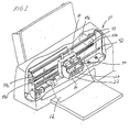
- FIG. 1 there is shown an ink jet printing apparatus 10 having first and second print cartridges 20 and 30 constructed in accordance with the present invention.
- the cartridges 20 and 30 are supported in a carrier 40 which, in turn, is slidably supported on a guide rail 42.
- a drive mechanism 44 is provided for effecting reciprocating movement of the carrier 40 back and forth along the guide rail 42.
- the drive mechanism 44 includes a motor 44a with a drive pulley 44b and a drive belt 44c which extends about the drive pulley 44b and an idler pulley 44d.
- the carrier 40 is fixedly connected to the drive belt 44c so as to move with the drive belt 44c.
- Operation of the motor 44a effects back and forth movement of the drive belt 44c and, hence, back and forth movement of the carrier 40 and the print cartridges 20 and 30.
- the print cartridges 20 and 30 move back and forth, they eject ink droplets onto a paper substrate 12 provided below them.
- the first print cartridge 20 ejects black ink droplets while the second print cartridge 30 ejects color droplets of either cyan, magenta or yellow ink. Only the first print cartridge 20 will be discussed in detail herein as the second print cartridge 30 is constructed in essentially the same manner as the first print cartridge 20.
- the print cartridge 20 comprises a polymeric container 22, see Fig. 1, filled with ink and a printhead 24, see Figs. 2 and 3.
- the printhead 24 comprises a heater chip 50 having a plurality of resistive heating elements 52.
- the printhead 24 further includes a plate 54 having a plurality of openings 56 extending through it which define a plurality of orifices 56a through which droplets are ejected.
- the plate 54 may be bonded to the chip 50 via any art recognized technique, including a thermocompression bonding process.
- sections 54a of the plate 54 and portions 50a of the heater chip 50 define a plurality of bubble chambers 55.
- Ink supplied by the container 22 flows into the bubble chambers 55 through ink supply channels 58.
- the resistive heating elements 52 are positioned on the heater chip 50 such that each bubble chamber 55 has only one heating element 52.
- Each bubble chamber 55 communicates with one orifice 56a, see Fig. 3.
- the resistive heating elements 52 are individually addressed by voltage pulses provided by a printer energy supply circuit 100, see Fig. 5. Each voltage pulse is applied to one of the heating elements 52 to momentarily vaporize the ink in contact with that heating element 52 to form a bubble within the bubble chamber 55 in which the heating element 52 is located. The function of the bubble is to displace ink within the bubble chamber 55 such that a droplet of ink is expelled from an orifice 56a associated with the bubble chamber 55.
- a flexible circuit 25 secured to the polymeric container 22 is used to provide a path for energy pulses to travel from the printer energy supply circuit 100 to the heater chip 50, see Fig. 5. Bond pads (not shown) on the heater chip 50 are bonded to end sections of traces (not shown) on the flexible circuit 25. Current flows from the printer energy supply circuit 100 to the traces on the flexible circuit 25 and from the traces to the bond pads on the heater chip 50. The current then flows from the bond pads along conductors 53 to the heating elements 52.
- a flexible circuit coupled to heater chip bond pads is disclosed in commonly assigned, copending patent application, U.S. Serial No.
- a layer 60 of thermally conductive material is located between the container 22 and the heater chip 50 so as to directly contact the heater chip 50, see Fig. 5.
- Any one of a number of thermally conductive materials may be used to form the layer 60 such as gold, aluminum, stainless steel, copper with or without a protective plating of nickel or chromium, carbon-filled polymers, and thermally conductive ceramics. If ink 23 contacts the layer 60, a substantially non-corrosive, thermally conductive material, such as aluminum, aluminum or copper with a protective plating of nickel or chromium, may be preferred.
- the layer 60 is substantially L-shaped, as shown in Fig. 5, and extends between inner and outer portions 22a and 22b of the container 22.
- the container 22 is formed from a thermally insulative polymeric material.
- the container 22 is formed from polyphenylene oxide, which is commercially available from the General Electric Company under the trademark "NORYL SE-1.” Other polymeric materials not explicitly set out herein may also be used.
- thermoelectric cooling cell 70 is coupled to the container 22 via a thermally conductive adhesive such that a first surface 70a of the cooling cell 70 contacts the conductive layer 60, see Fig. 5.
- a heat sink 80 is positioned adjacent to the cooling cell 70 such that an inner surface 80a of the heat sink 80 contacts a second surface 70b of the cooling cell 70.
- An outer surface 80b of the heat sink 80 is exposed to air.
- the heat sink 80 may have fins or ribs (not shown) to maximize heat transfer to the air.
- the conductive layer 60 provides a path for energy in the form of heat to flow from the heater chip 50 to the cooling cell 70.
- the cooling cell 70 transfers heat away from the conductive layer 60 to the heat sink 80 where the energy is dissipated to outside air exposed to the second surface 80b of the heat sink 80.
- a portion 80c of the heat sink 80 contacts the ink 23 to permit heat to be transferred directly from the heat sink 80 to the ink 23.
- Heating the ink has the advantage that some dissolved gases in the ink will be devolved thus reducing the formation of gas bubbles near the heater chip 50 which can cause print defects.
- the heat sink 80 is not in contact with the ink at surface 80c, but is enclosed by thermally insulative polymeric material and is solely in contact with outside air for heat exchange from the cooling cell 70.
- the heat sink 80 is not in contact with outside air, but is solely in contact with ink 23 for heat exchange from the cooling cell 70.
- thermally conductive materials may be used to form the heat sink 80 such as gold, copper with or without a protective plating of nickel or chromium, aluminum, stainless steel, carbon-filled polymers, and thermally conductive ceramics. If ink 23 contacts the heat sink 80, a substantially non-corrosive, thermally conductive material, such as aluminum or copper with a protective plating of nickel or chromium, may be preferred.
- the cell 70 comprises a peltier effect cooling cell. It may be formed from p-type and n-type semiconductor materials which are combined to form a pn junction.
- the preferred p-type materials include alloys of bismuth, tellurium and antimony while the preferred n-type materials include bismuth, tellurium and selenium.
- Conductor lines (not shown) extend from the flexible circuit 25 to the cooling cell 70. The conductor lines may extend along the outer surface of the container 22 or may be embedded within the container 22.
- Energy provided to the cooling cell 70 from the printer energy supply circuit 100 passes through the flexible circuit 25 and the conductor lines to the cooling cell 70. Heat is evolved or absorbed at the pn junction depending upon the direction of the current passing through it. The amount of heat evolved or absorbed is a function of current flow through the pn junction of the cell 70.
- Many forms of peltier effect cooling cells are commercially available and may be selected depending upon the physical shape and size requirements as well as the heat load they are to handle.
- a microprocessor 110 constantly monitors power provided by the printer energy supply circuit 100 to the heater chip 50.
- a typical amount of energy required to fire one of the heating elements 52 is stored in the microprocessor 110.
- the microprocessor 110 determines estimated power provided to the heater chip 50 during the given time period.
- the microprocessor 110 then causes the energy supply circuit 100 to supply current to the cooling cell 70 as a function of energy flow or estimated power provided to the heater chip 50 so as to cool the heater chip 50 and maintain the temperature of the heater chip 50 substantially constant or within a desired temperature range. It is presently preferred for current to be provided to the cooling cell 70 in direct proportion to the printload such that as printload increases, current provided to the cooling cell 70 increases and as printload decreases, current provided to the cooling cell 70 decreases.
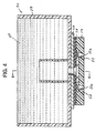
- a print cartridge 120 constructed in accordance with a second embodiment of the present invention is illustrated in Figs. 6 and 7, wherein like reference numerals indicate like elements.
- the print cartridge 120 includes an ink-filled container 122 which preferably is formed from a thermally non-conductive polymeric material.
- the container 122 includes an internal standpipe 122a which is preferably formed from a thermally non-conductive polymeric material.
- a layer 160 of thermally conductive material extends into the standpipe 122a and defines an internal passageway 160a through which the ink flows as it moves into the printhead 24.
- the layer of conductive material 160 also extends to the cooling cell 70 such that it contacts a first surface 70a of the cooling cell 70.
- thermally conductive materials may be used to form the layer 160, such as gold, aluminum, stainless steel, copper with or without a protective plating of nickel or chromium, carbon-filled polymers, and thermally conductive ceramics. Because ink 23 contacts the layer 160, a substantially non-corrosive, thermally conductive material, such as aluminum, or copper with a protective plating of nickel or chromium, may be preferred.
- the ink 23 flows through the passageway 160a and contacts the thermally conductive material 160, energy in the form of heat is removed from the ink 23.
- the energy moves via conduction along the material layer 160 to the cooling cell 70.
- the cooling cell 70 then transfers the heat to the heat sink 80 where the energy is dissipated to outside air.
- ink contained in an ink jet print cartridge container contains dissolved gases, primarily nitrogen, oxygen and carbon dioxide.
- gases primarily nitrogen, oxygen and carbon dioxide.
- the ink 23 is cooled before it enters the printhead 24, air is less likely to come out of solution as the ink 23 passes through the printhead 24.
- the cooled ink 23 also serves to cool the heater chip 50 as it flows into and through the printhead 24.
- ink cooling takes place solely in the standpipe 122a in the illustrated embodiment, only a very small quantity of ink about to be used for printing is cooled. This is preferred over cooling all of the ink in the container 122, which would require more power and encourage the absorption of additional gases into the ink, which is undesirable.
- the thermally conductive layer 160 is encased within the polymeric container 122 such that a layer of thermally insulating polymeric material 122b is located between the thermally conductive layer 160 and the heater chip 50.
- This allows the heat to be extracted from the ink only, lowering its temperature and reducing problems associated with gases devolving from the ink due to a temperature rise in proximity to the heater chip 50. A significant temperature drop could cause previously generated bubbles in the area of the heater chip 50 to dissolve back into the ink.
- thermally conductive layer 160 may directly contact the heater chip 50 so as to provide a path for heat to move from the heater chip 50 to the cooling cell 70 though this configuration would provide more benefit to directly cooling the heater chip 50, and could increase the temperature of the ink in proximity to the heater chip 50.
- an ink temperature sensor (not shown) may be provided in the standpipe 122a or between the heater chip 50 and the standpipe 122a for generating feedback signals to the microprocessor 110 representative of ink temperature. Based upon these signals, the microprocessor 110 causes the energy supply circuit 100 to supply an appropriate amount of current to the cooling cell 70 to maintain the temperature of the ink 23 substantially constant or within a desired temperature range.
- the temperature sensor may comprise a conventional thermistor or thermocouple.
- a heater chip temperature sensor (not shown) may be provided on or incorporated within the heater chip 50 which generates feedback signals to the microprocessor 110 representative of the heater chip's temperature. Based upon these signals, the microprocessor 110 causes the energy supply circuit 100 to supply an appropriate amount of current to the cooling cell 70 to maintain the temperature of the heater chip 50 substantially constant or within a desired temperature range.
- the temperature sensor may comprise a conventional thermistor or thermocouple.
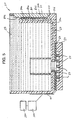
- a print cartridge 150 constructed in accordance with a third embodiment of the present invention is illustrated in Figs. 8 and 9, wherein like reference numerals indicate like elements.
- the print cartridge 150 includes an ink-filled container 152 which preferably is formed from the same material used to form the container 22.
- the cartridge 150 additionally includes an appropriately sized cooling cell 170 which directly contacts the heater chip 50 to cool same.
- a layer of thermally conductive material 160 extends from the cooling cell 170 to a heat sink 80 so as to provide a path for energy in the form of heat to flow from the cooling cell 170 to the heat sink 80.
- the thermally conductive layer 160 may be formed from any one of the materials set out above from which the conductive layer 60 is made. Further, the thermally conductive layer 160 and the heat sink 80 may comprise a single integral element.
- the cooling cell 170 may be operated and controlled in the same fashion as the cooling cell 70 described above.
- one or more cooling cells may be used to cool a pagewide printhead.
Landscapes
- Physics & Mathematics (AREA)
- Thermal Sciences (AREA)
- Particle Formation And Scattering Control In Inkjet Printers (AREA)
- Ink Jet (AREA)
- Accessory Devices And Overall Control Thereof (AREA)
Applications Claiming Priority (2)
| Application Number | Priority Date | Filing Date | Title |
|---|---|---|---|
| US878284 | 1997-06-18 | ||
| US08/878,284 US6193349B1 (en) | 1997-06-18 | 1997-06-18 | Ink jet print cartridge having active cooling cell |
Publications (2)
| Publication Number | Publication Date |
|---|---|
| EP0885721A2 true EP0885721A2 (de) | 1998-12-23 |
| EP0885721A3 EP0885721A3 (de) | 2000-03-29 |
Family
ID=25371725
Family Applications (1)
| Application Number | Title | Priority Date | Filing Date |
|---|---|---|---|
| EP98111029A Withdrawn EP0885721A3 (de) | 1997-06-18 | 1998-06-16 | Tintenstrahldruckpatrone mit aktiver Kühlzelle |
Country Status (5)
| Country | Link |
|---|---|
| US (1) | US6193349B1 (de) |
| EP (1) | EP0885721A3 (de) |
| JP (1) | JPH1110913A (de) |
| KR (1) | KR19990007047A (de) |
| CN (1) | CN1083335C (de) |
Cited By (3)
| Publication number | Priority date | Publication date | Assignee | Title |
|---|---|---|---|---|
| EP1508452A1 (de) * | 2003-08-19 | 2005-02-23 | Konica Minolta Business Technologies, Inc. | Tintendrucker |
| WO2005102709A1 (en) * | 2004-04-23 | 2005-11-03 | Hewlett-Packard Development Company, L.P. | Inkjet print cartridge |
| US20230062172A1 (en) * | 2020-02-20 | 2023-03-02 | Control Print Limited | Thermal inkjet printer with integrated cooling |
Families Citing this family (13)
| Publication number | Priority date | Publication date | Assignee | Title |
|---|---|---|---|---|
| US6607259B2 (en) | 2001-10-11 | 2003-08-19 | Hewlett-Packard Development Company, L.P. | Thermal inkjet printer having enhanced heat removal capability and method of assembling the printer |
| US6581388B2 (en) | 2001-11-27 | 2003-06-24 | Sun Microsystems, Inc. | Active temperature gradient reducer |
| US6648443B1 (en) * | 2002-06-18 | 2003-11-18 | Hewlett-Packard Development Company, L.P. | Thermal inkjet print head with a temperature regulation system and methods of making and using the same |
| JP4207678B2 (ja) * | 2003-06-18 | 2009-01-14 | 日産自動車株式会社 | リチウムイオン電池型二次電池用電極の製造方法およびその装置並びにリチウムイオン電池型二次電池用電極 |
| US7311044B1 (en) | 2003-10-14 | 2007-12-25 | Hewlett-Packard Development Company, L.P. | Imaging device cooling system |
| US7469986B2 (en) * | 2005-12-30 | 2008-12-30 | Nu-Kote International, Inc. | Marking material cartridge with processor having configurable logic |
| US8454144B2 (en) * | 2010-01-08 | 2013-06-04 | Xerox Corporation | Ink storage reservoir for a solid ink printhead |
| JP5845717B2 (ja) * | 2011-08-22 | 2016-01-20 | セイコーエプソン株式会社 | 記録装置 |
| CN103857492B (zh) * | 2011-09-16 | 2016-03-02 | 株式会社Ksm | 产生少量金属粉尘的波纹管焊接用冷却环 |
| WO2017011008A1 (en) * | 2015-07-15 | 2017-01-19 | Hewlett-Packard Development Company, L.P. | Powering a power monitor |
| CN108162615A (zh) * | 2017-12-21 | 2018-06-15 | 上海万琛电子商务有限公司 | 一种具有散热功能的电子面单打印机 |
| CN108481916A (zh) * | 2018-04-06 | 2018-09-04 | 崔浩轩 | 一种喷码机用墨盒装置 |
| KR101941087B1 (ko) | 2018-06-28 | 2019-01-23 | 주식회사 딜리 | 인쇄용지의 열변형 방지를 위한 프린터 냉각 장치를 이용한 프린터 냉각 방법 |
Citations (6)
| Publication number | Priority date | Publication date | Assignee | Title |
|---|---|---|---|---|
| JPS5582663A (en) * | 1978-12-20 | 1980-06-21 | Canon Inc | Recording medium liquid jet recording method by heat energy |
| JPS61242847A (ja) * | 1985-04-19 | 1986-10-29 | Ricoh Co Ltd | インクジエツト記録装置における消泡装置 |
| JPS6463148A (en) * | 1987-09-03 | 1989-03-09 | Ricoh Kk | Ink jet recording method |
| JPH01108051A (ja) * | 1987-10-22 | 1989-04-25 | Canon Inc | 記録装置 |
| JPH03202361A (ja) * | 1989-08-25 | 1991-09-04 | Ricoh Co Ltd | 半導体装置およびそれを用いたサーマルプリンタヘッド |
| JPH04353462A (ja) * | 1991-05-31 | 1992-12-08 | Nec Corp | サーマルインクジェットプリンタ |
Family Cites Families (24)
| Publication number | Priority date | Publication date | Assignee | Title |
|---|---|---|---|---|
| JPS5451837A (en) | 1977-09-30 | 1979-04-24 | Ricoh Co Ltd | Ink jet head device |
| CA1127227A (en) | 1977-10-03 | 1982-07-06 | Ichiro Endo | Liquid jet recording process and apparatus therefor |
| JPS5830824B2 (ja) | 1978-06-07 | 1983-07-01 | 株式会社リコー | インクジェット記録装置のインクジェットヘッド |
| US4296421A (en) * | 1978-10-26 | 1981-10-20 | Canon Kabushiki Kaisha | Ink jet recording device using thermal propulsion and mechanical pressure changes |
| JPS60115450A (ja) | 1983-11-26 | 1985-06-21 | Sanyo Electric Co Ltd | インクジェット印写装置 |
| JPS60115457A (ja) | 1983-11-28 | 1985-06-21 | Sanyo Electric Co Ltd | インクジェット印写装置 |
| JPH0667655B2 (ja) | 1985-10-08 | 1994-08-31 | 株式会社サト− | 熱記録式プリンタ |
| US4797837A (en) * | 1986-04-24 | 1989-01-10 | Ncr Canada Ltd. - Ncr Canada Ltee | Method and apparatus for thermal printer temperature control |
| US4751528A (en) | 1987-09-09 | 1988-06-14 | Spectra, Inc. | Platen arrangement for hot melt ink jet apparatus |
| US4831390A (en) | 1988-01-15 | 1989-05-16 | Xerox Corporation | Bubble jet printing device with improved printhead heat control |
| US5175565A (en) | 1988-07-26 | 1992-12-29 | Canon Kabushiki Kaisha | Ink jet substrate including plural temperature sensors and heaters |
| DE68914897T2 (de) | 1988-07-26 | 1994-08-25 | Canon Kk | Flüssigkeitsstrahlaufzeichnungskopf und Aufzeichnungsgerät, versehen mit diesem Kopf. |
| US5107276A (en) | 1989-07-03 | 1992-04-21 | Xerox Corporation | Thermal ink jet printhead with constant operating temperature |
| US5121343A (en) * | 1990-07-19 | 1992-06-09 | Faris Sadeg M | 3-D stereo computer output printer |
| US5272491A (en) | 1990-10-31 | 1993-12-21 | Hewlett-Packard Company | Thermal ink jet print device having phase change cooling |
| JP3170311B2 (ja) | 1991-07-29 | 2001-05-28 | キヤノン株式会社 | 記録ヘッドおよび記録装置 |
| JPH05201102A (ja) | 1992-01-27 | 1993-08-10 | Minolta Camera Co Ltd | 機械装置における冷却ファンの制御装置 |
| GB9205343D0 (en) * | 1992-03-12 | 1992-04-22 | Willett Int Ltd | Temperature control system |
| US5406321A (en) | 1993-04-30 | 1995-04-11 | Hewlett-Packard Company | Paper preconditioning heater for ink-jet printer |
| US5622897A (en) | 1993-05-20 | 1997-04-22 | Compaq Computer Corporation | Process of manufacturing a drop-on-demand ink jet printhead having thermoelectric temperature control means |
| US5610635A (en) * | 1994-08-09 | 1997-03-11 | Encad, Inc. | Printer ink cartridge with memory storage capacity |
| JPH1063148A (ja) * | 1996-08-23 | 1998-03-06 | Ricoh Co Ltd | 湿式画像形成装置 |
| JPH118051A (ja) * | 1997-06-13 | 1999-01-12 | Toshiba Corp | 加熱調理器 |
| JPH1110912A (ja) | 1997-06-18 | 1999-01-19 | Lexmark Internatl Inc | 冷却セルを有するインク・ジェット・プリント・カートリッジ |
-
1997
- 1997-06-18 US US08/878,284 patent/US6193349B1/en not_active Expired - Lifetime
-
1998
- 1998-06-11 JP JP10179645A patent/JPH1110913A/ja not_active Withdrawn
- 1998-06-16 EP EP98111029A patent/EP0885721A3/de not_active Withdrawn
- 1998-06-17 KR KR1019980022650A patent/KR19990007047A/ko not_active Application Discontinuation
- 1998-06-18 CN CN98114975A patent/CN1083335C/zh not_active Expired - Fee Related
Patent Citations (6)
| Publication number | Priority date | Publication date | Assignee | Title |
|---|---|---|---|---|
| JPS5582663A (en) * | 1978-12-20 | 1980-06-21 | Canon Inc | Recording medium liquid jet recording method by heat energy |
| JPS61242847A (ja) * | 1985-04-19 | 1986-10-29 | Ricoh Co Ltd | インクジエツト記録装置における消泡装置 |
| JPS6463148A (en) * | 1987-09-03 | 1989-03-09 | Ricoh Kk | Ink jet recording method |
| JPH01108051A (ja) * | 1987-10-22 | 1989-04-25 | Canon Inc | 記録装置 |
| JPH03202361A (ja) * | 1989-08-25 | 1991-09-04 | Ricoh Co Ltd | 半導体装置およびそれを用いたサーマルプリンタヘッド |
| JPH04353462A (ja) * | 1991-05-31 | 1992-12-08 | Nec Corp | サーマルインクジェットプリンタ |
Non-Patent Citations (6)
| Title |
|---|
| PATENT ABSTRACTS OF JAPAN vol. 004, no. 125 (M-030), 3 September 1980 (1980-09-03) & JP 55 082663 A (CANON INC), 21 June 1980 (1980-06-21) * |
| PATENT ABSTRACTS OF JAPAN vol. 011, no. 090 (M-573), 20 March 1987 (1987-03-20) & JP 61 242847 A (RICOH CO LTD), 29 October 1986 (1986-10-29) * |
| PATENT ABSTRACTS OF JAPAN vol. 013, no. 258 (M-838), 15 June 1989 (1989-06-15) & JP 01 063148 A (RICOH CO LTD), 9 March 1989 (1989-03-09) * |
| PATENT ABSTRACTS OF JAPAN vol. 013, no. 320 (M-853), 20 July 1989 (1989-07-20) & JP 01 108051 A (CANON INC), 25 April 1989 (1989-04-25) * |
| PATENT ABSTRACTS OF JAPAN vol. 015, no. 473 (M-1185), 29 November 1991 (1991-11-29) & JP 03 202361 A (RICOH CO LTD), 4 September 1991 (1991-09-04) * |
| PATENT ABSTRACTS OF JAPAN vol. 017, no. 217 (M-1403), 28 April 1993 (1993-04-28) & JP 04 353462 A (NEC CORP), 8 December 1992 (1992-12-08) * |
Cited By (5)
| Publication number | Priority date | Publication date | Assignee | Title |
|---|---|---|---|---|
| EP1508452A1 (de) * | 2003-08-19 | 2005-02-23 | Konica Minolta Business Technologies, Inc. | Tintendrucker |
| US7134750B2 (en) | 2003-08-19 | 2006-11-14 | Konica Minolta Business Technologies, Inc. | Ink jet printer |
| WO2005102709A1 (en) * | 2004-04-23 | 2005-11-03 | Hewlett-Packard Development Company, L.P. | Inkjet print cartridge |
| US7832839B2 (en) | 2004-04-23 | 2010-11-16 | Hewlett-Packard Development Company, L.P. | Inkjet print cartridge |
| US20230062172A1 (en) * | 2020-02-20 | 2023-03-02 | Control Print Limited | Thermal inkjet printer with integrated cooling |
Also Published As
| Publication number | Publication date |
|---|---|
| JPH1110913A (ja) | 1999-01-19 |
| CN1202423A (zh) | 1998-12-23 |
| US6193349B1 (en) | 2001-02-27 |
| EP0885721A3 (de) | 2000-03-29 |
| KR19990007047A (ko) | 1999-01-25 |
| CN1083335C (zh) | 2002-04-24 |
Similar Documents
| Publication | Publication Date | Title |
|---|---|---|
| US6193349B1 (en) | Ink jet print cartridge having active cooling cell | |
| EP0841166A2 (de) | Sprühvorrichtung für Tintenstrahldrucker | |
| US6799822B2 (en) | High quality fluid ejection device | |
| US5107276A (en) | Thermal ink jet printhead with constant operating temperature | |
| US4980702A (en) | Temperature control for an ink jet printhead | |
| JPH0717054A (ja) | 温度保持装置 | |
| US4831390A (en) | Bubble jet printing device with improved printhead heat control | |
| JPH11320889A (ja) | 薄膜インクジェットプリントヘッド | |
| JP2009012223A (ja) | インクジェット記録ヘッド | |
| US6296350B1 (en) | Ink jet printer having driver circuit for generating warming and firing pulses for heating elements | |
| US7488056B2 (en) | Fluid ejection device | |
| EP0885737A1 (de) | Tintenstrahlaufzeichnungspatrone mit aktiver Kühlzelle | |
| JPH10286964A (ja) | インクジェット装置、該装置用インクジェットヘッドの温度推定方法および制御方法 | |
| US5975669A (en) | Ink-jet recording apparatus and recording method | |
| US5734392A (en) | Ink jet printhead heating during margin periods | |
| US5467113A (en) | Ink-jet recording head, board for said head and ink-jet recording apparatus | |
| EP1419887B1 (de) | Flüssigkeitsausstossverfahren und -Vorrichtung | |
| US6247779B1 (en) | Printhead configuration | |
| US6364464B1 (en) | Spray device for ink-jet printer and its spraying method | |
| JPH03213352A (ja) | インクジェット記録装置 | |
| JPH03234632A (ja) | インクジェット記録装置 | |
| JPH10166586A (ja) | 液体吐出ヘッド、液体吐出ヘッドカートリッジおよび液体吐出装置 | |
| EP0478781A1 (de) | Farbstrahlaufzeichnungskopf, substrat dafür und vorrichtung | |
| JPH0343254A (ja) | 熱インクジェットの印字ヘッド | |
| JPH0358849A (ja) | インクジェット記録装置 |
Legal Events
| Date | Code | Title | Description |
|---|---|---|---|
| PUAI | Public reference made under article 153(3) epc to a published international application that has entered the european phase |
Free format text: ORIGINAL CODE: 0009012 |
|
| AK | Designated contracting states |
Kind code of ref document: A2 Designated state(s): DE FR GB |
|
| AX | Request for extension of the european patent |
Free format text: AL;LT;LV;MK;RO;SI |
|
| PUAL | Search report despatched |
Free format text: ORIGINAL CODE: 0009013 |
|
| AK | Designated contracting states |
Kind code of ref document: A3 Designated state(s): AT BE CH CY DE DK ES FI FR GB GR IE IT LI LU MC NL PT SE |
|
| AX | Request for extension of the european patent |
Free format text: AL;LT;LV;MK;RO;SI |
|
| RIC1 | Information provided on ipc code assigned before grant |
Free format text: 7B 41J 2/05 A, 7B 41J 2/175 B, 7B 41J 29/377 B |
|
| 17P | Request for examination filed |
Effective date: 20000816 |
|
| AKX | Designation fees paid |
Free format text: DE FR GB |
|
| 17Q | First examination report despatched |
Effective date: 20031218 |
|
| STAA | Information on the status of an ep patent application or granted ep patent |
Free format text: STATUS: THE APPLICATION HAS BEEN WITHDRAWN |
|
| 18W | Application withdrawn |
Effective date: 20040209 |