EP0882631A2 - Procédé de freinage d'un véhicule - Google Patents
Procédé de freinage d'un véhicule Download PDFInfo
- Publication number
- EP0882631A2 EP0882631A2 EP98105919A EP98105919A EP0882631A2 EP 0882631 A2 EP0882631 A2 EP 0882631A2 EP 98105919 A EP98105919 A EP 98105919A EP 98105919 A EP98105919 A EP 98105919A EP 0882631 A2 EP0882631 A2 EP 0882631A2
- Authority
- EP
- European Patent Office
- Prior art keywords
- braking
- friction
- value
- wheel
- principle
- Prior art date
- Legal status (The legal status is an assumption and is not a legal conclusion. Google has not performed a legal analysis and makes no representation as to the accuracy of the status listed.)
- Granted
Links
Images

Classifications
-
- B—PERFORMING OPERATIONS; TRANSPORTING
- B60—VEHICLES IN GENERAL
- B60T—VEHICLE BRAKE CONTROL SYSTEMS OR PARTS THEREOF; BRAKE CONTROL SYSTEMS OR PARTS THEREOF, IN GENERAL; ARRANGEMENT OF BRAKING ELEMENTS ON VEHICLES IN GENERAL; PORTABLE DEVICES FOR PREVENTING UNWANTED MOVEMENT OF VEHICLES; VEHICLE MODIFICATIONS TO FACILITATE COOLING OF BRAKES
- B60T8/00—Arrangements for adjusting wheel-braking force to meet varying vehicular or ground-surface conditions, e.g. limiting or varying distribution of braking force
- B60T8/17—Using electrical or electronic regulation means to control braking
- B60T8/176—Brake regulation specially adapted to prevent excessive wheel slip during vehicle deceleration, e.g. ABS
- B60T8/1764—Regulation during travel on surface with different coefficients of friction, e.g. between left and right sides, mu-split or between front and rear
-
- B—PERFORMING OPERATIONS; TRANSPORTING
- B60—VEHICLES IN GENERAL
- B60T—VEHICLE BRAKE CONTROL SYSTEMS OR PARTS THEREOF; BRAKE CONTROL SYSTEMS OR PARTS THEREOF, IN GENERAL; ARRANGEMENT OF BRAKING ELEMENTS ON VEHICLES IN GENERAL; PORTABLE DEVICES FOR PREVENTING UNWANTED MOVEMENT OF VEHICLES; VEHICLE MODIFICATIONS TO FACILITATE COOLING OF BRAKES
- B60T8/00—Arrangements for adjusting wheel-braking force to meet varying vehicular or ground-surface conditions, e.g. limiting or varying distribution of braking force
- B60T8/32—Arrangements for adjusting wheel-braking force to meet varying vehicular or ground-surface conditions, e.g. limiting or varying distribution of braking force responsive to a speed condition, e.g. acceleration or deceleration
- B60T8/58—Arrangements for adjusting wheel-braking force to meet varying vehicular or ground-surface conditions, e.g. limiting or varying distribution of braking force responsive to a speed condition, e.g. acceleration or deceleration responsive to speed and another condition or to plural speed conditions
Definitions
- the invention relates to a method for braking a Vehicle in which the at least one axis respective braking forces on the wheels of this axle a common braking value, in particular a common one Brake pressure that can be influenced on roads with changing coefficient of friction according to the preamble of the claim 1.
- Generic methods are usually used in conjunction with pressure fluid operated and with an anti-lock braking system equipped braking systems used. They can also be used in electrically controlled braking systems (EBS) are used. Here are used for registration the speed of rotation of the vehicle wheels sensors and to adjust the braking forces on the vehicle wheels so-called pressure modulators are used. With such Vehicle wheels provided with sensors are described below also known as sensed bikes. As pressure modulators z. B. solenoid valves used. The Braking forces are due to one in the following as Brake signal designated signal determined. As a braking value any size can be used in the brake system which affects the braking forces. In a conventional one Brake system is usually used as the braking value brake pressure influenced by the pressure modulator is used. In an electrically controlled braking system also an electrical signal used as a braking value will.
- EBS electrically controlled braking systems
- a control unit evaluates the Rotation speed signals from the sensed wheels and influences the braking forces on the wheels by means of the braking value.
- the control concept described above has the disadvantage that that with an increase in the initially low coefficient of friction to a higher value during select high control the blocked wheel in many cases not again starts and the tire is damaged. Since the wheel locks permanently, it is also not possible due to its rotational speed signal to recognize such changes in the coefficient of friction.
- the invention is therefore based on the object Method for braking a vehicle in which the respective braking forces on at least one axis the wheels of this axle by a common braking value can be influenced on lanes with changing Specify coefficients of friction by which a short braking distance is achieved and when the coefficient of friction changes, in particular on an initially low coefficient of friction Wheel, can be recognized at any time.
- each is used as the braking value Understand size in a braking system by which the Braking forces on the vehicle wheels can be influenced.
- the slip of a wheel with braking force is the difference between the vehicle speed and the speed of rotation of this wheel. As relative slip becomes the percentage of the previous described slip at the vehicle speed Understood.
- Blocking a wheel is understood to mean a condition in which the relative slip is at least approximately one 100% reached. With smaller slip values there is only a tendency to lock.
- An advantage of the invention is that in a Braking on a road with different Coefficients of friction on both sides of the vehicle also a slight one Increase the lower of the two coefficients of friction is quickly recognized. As a result, can also quickly be decided whether to continue this used control principle, in which the on the lower Wheel at least temporarily blocked, allowed, or whether due to expected Tire damage with a different regulation principle must continue, where the Blocking the wheel is avoided.
- the aforementioned condition can already be met in that the locked wheel on one Road section arrives on which the available The coefficient of friction is considerably higher, so that despite the low Adequate use of friction when blocking high friction occurs. In this case the wheel is running without additional measures. A recognizable one Damage to the tire does not occur.
- a second control principle provided that preferably on road surfaces with almost identical pages or only marginally mutually different coefficients of friction is used, and where none of the wheels are blocked. This will make the Cornering power of the wheels increased and thus the Driving stability of the vehicle when braking in one Curve improved. That way one can be special flexible type of braking force control for many in the Friction coefficient combinations that occur in practice can be achieved.
- Another advantage is that the first control principle with an increase in the lower coefficient of friction not generally canceled, but that depending on the size of the increase coming from the Rotational speed signals in each case according to an inventive Brake force reduction can be derived can be decided, according to which regulatory principle taking into account possible tire damage and the braking distance must be continued. Hereby a particularly high level of security is achieved.
- the invention as part of a higher-level control concept used, in which various individual control principles for different road conditions are provided.
- the regulatory principle is an assessment of the Difference between the coefficients of friction on the sides of the vehicle intended.
- a ⁇ -split value determines the difference between the coefficients of friction.
- yet another regulation principle can be provided, the preferably on lanes with almost sides same or only slightly different friction values is used and in which none of the wheels blocked.
- the further regulation principle can with the second regulation principle to be identical.
- a particularly advantageous embodiment of the invention therefore has the following characteristics:
- the invention is advantageously used in such Brake systems used in which an increase in Braking value causes an increase in braking forces and a reduction in the braking value a reduction in the Braking forces.
- a Proportional relationship between the sizes of the braking value and braking force is not limited to such use cases.
- the braking forces are reduced by influencing of the braking value increased so that the higher Wheel located has a tendency to lock.
- the shortest possible braking distance can be achieved because the existing (higher) coefficient of friction is as possible is well exploited.
- the braking forces at certain time intervals will be briefly reduced outside the time intervals in order to make the best possible use of the coefficient of friction the braking forces through adaptive influence of the braking value at the respectively required Adjusted value.
- the braking forces can be even or gradually increased until a tendency to lock on the one with the higher coefficient of friction Wheel becomes recognizable.
- the first step is to recognize the mean of the Calculate rotational speed signals and this then on falling below a threshold monitor. Because during the first regulatory principle on the lower coefficient of friction in the to monitoring phases blocked, it does not provide any Contribution to the mean.
- the mean is therefore in substantially proportional to the rotational speed signal of the wheel with the higher coefficient of friction. This makes detection very simple and reliable blocking tendency possible. Also can the wheel with the higher coefficient of friction at which by means of the first regulation principle the available one Regulation should be used as well as possible with particularly small amplitudes of the control vibrations be achieved. This will make a good one Control comfort and a particularly high utilization of the coefficient of friction achieved.
- the aforementioned threshold is reduced when the Vehicle deceleration a very high or a very has low value. This will on road sections with low friction values, on which only one low vehicle deceleration can be achieved Driving stability increased. On road sections with high Coefficients of friction on which a high vehicle deceleration tire wear can be achieved reduced without the braking distance significantly is enlarged.
- the Braking value when transitioning to the first control principle changed continuously or finely according to a time function.
- a suitable time function a smooth, slow transition between the control types can be achieved. This can cause a sudden Avoid increases in yaw moment and steering forces become a surprise for the driver Driving behavior of the vehicle can be avoided.
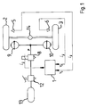
- Fig. 1 are the parts related to the invention a vehicle brake system shown. It is one Vehicle axle (14) is present on which two wheels (2, 3) are attached. The wheels are not shown Provide tires that the contact of the vehicle to the Make the road.
- the wheels (2, 3) are for braking each assigned a braking device (9, 10), by means of which the wheels are subjected to braking forces can be.
- the braking devices (9, 10) can in usual way as a pressure-operated drum or Disc brakes can be formed. Can be operated the braking devices (9, 10) via the valves (8, 12) be pressurized with a pressure medium that consists of a Pressure medium reservoir (13) is removed. More for the operation of such a pressure medium operated Brake system required components, such as e.g. B. a compressor for filling the pressure medium reservoir (13) are not shown in FIG. 1.
- the pressurization of the braking devices (9, 10) can be operated by the driver of the foot brake valve (12) can be controlled.
- the one specified by the foot brake valve (12) Brake pressure through the with the foot brake valve (12) Solenoid valve (8) connected in series can be influenced.
- the braking value in this exemplary embodiment is the Output pressure (P) of the solenoid valve (8) used.
- the Solenoid valve (8) serves as a brake pressure modulator. It is suitable for the on its input connection present pressure, which is released by the foot brake valve (12) will be reduced or at most equal high level to its output connection or to the Pass on braking devices (9, 10).
- the solenoid valve (8) can be used in the usual way as a 3/2-way valve be trained.
- the solenoid valve (8) is triggered by an electrical signal actuated by an electronic control unit (1) is produced.
- the electrical signal can be a simple one Be on / off signal. However, it can also be act a serial data signal provided the solenoid valve (8) via a corresponding evaluation option for such a signal.
- a microprocessor for execution is in the control unit (1) of the inventive method provided.
- the method according to the invention is then part of the Control program for the microprocessor trained.
- the rotational speed signals necessary for executing the method the wheels (2, 3) are the control unit (1) supplied as input signals by means of rotational speed sensors (5, 6) can be determined.
- Pressure sensor for sensing the solenoid valve (8) output pressure (P) must be present, whose signal then also to the control unit (1) as Input signal is supplied.
- FIG. 2 the physically different quantities are plotted in separate diagrams which are correlated with one another in time.
- the speed signals (V 2 , V 3 ) of the wheels (2, 3) and the vehicle speed are shown in a diagram. In this case, these signals can have the same value at times, so that then three separate curves are not visible. In the event of deviations between these signals, reference signs are assigned to the respective curve profiles if this is necessary for an understanding of the invention.
- FIG. 2 contains separate diagrams.
- a fictitious initial state is initially assumed, in which the vehicle is already traveling at an initial speed (V 0 ) and is braked at a point in time (20).
- V 0 initial speed
- V 2 initial speed
- braking already starts on a road section with different coefficients of friction.
- the sequence of the method according to the invention is analogous to the illustration in FIG. 2, the phase (34) between the times (21, 22) then being missing.
- the vehicle Before time (20), the vehicle is moving at the initial speed (V 0 ). The vehicle is neither accelerated nor braked, so that the vehicle speed and the rotational speed signals (V 2 , V 3 ) have the same value that is indicated by the line (40).
- the driver of the vehicle initiates braking of the vehicle by actuating the foot brake valve (12).
- the brake pressure (P) then increases over time with a vehicle-specific gradient.
- the rotational speeds of the wheels (2, 3) decrease faster than the vehicle speed, and braking slip occurs.
- the rotational speed signals (V 2 , V 3 ) are continuously evaluated in the control unit (1).
- a tendency to lock on the sensed wheels is then determined on the basis of the course of the rotational speeds (V 2 , V 3 ), in that the brake slip or a deceleration value derived therefrom exceeds a predetermined threshold.
- the brake pressure (P) is influenced in the context of a modified axis control according to DE 37 33 801 A1.
- the control unit (1) indicates electrical signals the solenoid valve (8) in such a way that at the highest possible Braking forces none of the wheels blocked. It arises the course of the phase shown in (34) Brake pressure (P). Since in phase (34) approximately even distribution of friction on both sides of the vehicle the speed curves are assumed (42, 43) of the sensed wheels in this phase also approximately the same. The vehicle speed decreases in this phase according to the curve (41).
- the in the Transition phase (31) initially increased evenly Brake pressure (P) increased further.
- P evenly Brake pressure
- a Brake pressure level can be reached at which the higher friction coefficient wheel (2) a tendency to lock if not an inventive one brief brake pressure reduction occurs. That on the Wheel (3) located at a lower coefficient of friction blocks here Completely.
- the brake pressure (P) is briefly reduced. Such brake pressure reduction will occur at the times (25, 27) and is z. B. from one Time monitoring function triggered.
- the time monitoring function can be used as a counter with a fixed counting time be formed, each after the expiry of Count time triggers a brake pressure reduction and after End of the brake pressure reduction again counting begins.
- a suitable value for the counting time is 400 ms.
- the duration of the brief brake pressure reduction depends on the type of brake system, the last one set Brake pressure level and other vehicle-specific sizes, e.g. B. the axle loads, and can by experiment be tailored to the respective application.
- a suitable value is 100 ms.
- the vote can also be done automatically by the control unit based on the last set Brake pressure levels taking into account the aforementioned Influencing variables, which then in the control unit The duration of the parameters have been saved Brake pressure reduction is calculated.
- the braking force on the wheel (2) with the higher coefficient of friction due to the increase in the braking pressure (P) outside the time intervals (37, 38, 39), reaches a value which leads to a tendency to lock on this wheel.
- the rotational speed signal (V 2 ) decreases according to the line (46). The reduction in the brake pressure at the point in time (26) is therefore not triggered on the basis of the time monitoring function, but rather on the course of the rotational speed signal (V 2 ).
- the brake pressure (P) At the end of one of the time intervals (37, 38, 39), in which the brake pressure (P) was initially reduced, the brake pressure will then quickly return to a higher level Level raised. This level corresponds approximately the one before the time interval Brake pressure level, but can also for safety reasons be chosen a little lower.
- valve (8) as a switchable valve with the Switching states “lower pressure”, “maintain pressure” and “Increase pressure” is trained, then to restore of the brake pressure level the duration of the Switching state “lower pressure” determined and in the Control unit (1) saved and then with the help of the stored value the duration of the switching state "Increase pressure” set.
- rapid restoration of a brake pressure level with the one with the higher coefficient of friction
- the friction coefficient available there is used as well as possible is, it is also possible to do that in front of each Time interval of the brake pressure reduction made Switching steps to increase the brake pressure to count and depending on the thus determined Add the braking force increase after a time interval Taxes. Also a combination of these two options is beneficial.
Landscapes
- Engineering & Computer Science (AREA)
- Transportation (AREA)
- Mechanical Engineering (AREA)
- Regulating Braking Force (AREA)
Applications Claiming Priority (2)
| Application Number | Priority Date | Filing Date | Title |
|---|---|---|---|
| DE19723323 | 1997-06-04 | ||
| DE19723323A DE19723323A1 (de) | 1997-06-04 | 1997-06-04 | Verfahren zur Abbremsung eines Fahrzeuges |
Publications (3)
| Publication Number | Publication Date |
|---|---|
| EP0882631A2 true EP0882631A2 (fr) | 1998-12-09 |
| EP0882631A3 EP0882631A3 (fr) | 2000-01-19 |
| EP0882631B1 EP0882631B1 (fr) | 2003-05-14 |
Family
ID=7831317
Family Applications (1)
| Application Number | Title | Priority Date | Filing Date |
|---|---|---|---|
| EP98105919A Expired - Lifetime EP0882631B1 (fr) | 1997-06-04 | 1998-04-01 | Procédé de freinage d'un véhicule |
Country Status (4)
| Country | Link |
|---|---|
| US (1) | US6116703A (fr) |
| EP (1) | EP0882631B1 (fr) |
| JP (1) | JP4218041B2 (fr) |
| DE (2) | DE19723323A1 (fr) |
Families Citing this family (5)
| Publication number | Priority date | Publication date | Assignee | Title |
|---|---|---|---|---|
| DE10135600A1 (de) * | 2001-07-20 | 2003-02-06 | Wabco Gmbh & Co Ohg | Antiblockiersystem |
| DE10221079B4 (de) * | 2002-05-11 | 2011-01-20 | Wabco Gmbh | Antiblockiersystem für ein Radfahrzeug |
| DE102004010233B4 (de) * | 2004-03-03 | 2021-09-16 | Zf Cv Systems Hannover Gmbh | Verfahren zur Abbremsung eines Fahrzeuges |
| US9278677B2 (en) | 2013-08-14 | 2016-03-08 | Bendix Commercial Vehicle Systems Llc | System and method for controlling respective braking pressures at wheels on a vehicle |
| US9346440B2 (en) * | 2014-08-14 | 2016-05-24 | Bendix Commercial Vehicle Systems Llc | System and method for controlling braking pressures at wheels on a vehicle |
Citations (2)
| Publication number | Priority date | Publication date | Assignee | Title |
|---|---|---|---|---|
| DE3733801A1 (de) | 1987-09-21 | 1989-03-30 | Wabco Westinghouse Fahrzeug | Antiblockiersystem fuer fahrzeuge |
| DE4410937C1 (de) | 1994-03-29 | 1995-08-10 | Knorr Bremse Systeme | Verfahren zur Optimierung von Bremsweg und Fahrzeugstabilität von Fahrzeugen mit einem Antiblockiersystem auf Fahrbahnen mit stark unterschiedlichen Reibwerten und blockiergeschützter Bremskraftregelkreis zur Durchführung des Verfahrens |
Family Cites Families (15)
| Publication number | Priority date | Publication date | Assignee | Title |
|---|---|---|---|---|
| DE2851107C2 (de) * | 1978-11-25 | 1990-03-08 | Wabco Westinghouse Fahrzeugbremsen GmbH, 3000 Hannover | Schaltungsanordnung zur Verbesserung der Fahrstabilität von mit blockiergeschützten Bremsanlagen ausgerüsteten Fahrzeugen |
| DE3671871D1 (de) * | 1985-12-05 | 1990-07-19 | Bosch Gmbh Robert | Antiblockierregelsystem fuer fahrzeuge. |
| DE3639864A1 (de) * | 1985-12-05 | 1987-06-11 | Bosch Gmbh Robert | Antiblockierregelsystem fuer fahrzeuge |
| US5224766A (en) * | 1990-11-09 | 1993-07-06 | Tokico Ltd. | Anti-skid control apparatus for a vehicle braking system |
| JPH04176766A (ja) * | 1990-11-09 | 1992-06-24 | Tokico Ltd | アンチスキッド制御装置 |
| DE4114734A1 (de) * | 1991-05-06 | 1992-11-12 | Teves Gmbh Alfred | Schaltungsanordnung fuer eine bremsanlage mit elektronischer blockierschutzregelung |
| GB9306979D0 (en) * | 1993-04-03 | 1993-05-26 | Grau Ltd | Vehicle braking system |
| DE4323275C2 (de) * | 1993-07-12 | 1997-02-20 | Lucas Ind Plc | Antriebsschlupfregelung |
| JPH07132816A (ja) * | 1993-11-09 | 1995-05-23 | Akebono Brake Ind Co Ltd | アンチロック制御方法 |
| JP3004861B2 (ja) * | 1994-01-27 | 2000-01-31 | ボッシュ ブレーキ システム株式会社 | 一軸・一モジュレータ・二車輪速センサを備える車両のアンチスキッドブレーキ制御方法 |
| DE4446582B4 (de) * | 1994-12-24 | 2005-11-17 | Robert Bosch Gmbh | Fahrdynamikregelsystem |
| JPH0995228A (ja) * | 1995-09-29 | 1997-04-08 | Mazda Motor Corp | 車両の制動力制御装置 |
| GB2307526A (en) * | 1995-11-27 | 1997-05-28 | Lucas Ind Plc | A braking system for a vehicle |
| DE19707106B4 (de) * | 1996-03-30 | 2008-12-04 | Robert Bosch Gmbh | System zur Ansteuerung von Bremssystemen |
| JP3380397B2 (ja) * | 1996-05-27 | 2003-02-24 | 三菱電機株式会社 | アンチロックブレーキ制御装置 |
-
1997
- 1997-06-04 DE DE19723323A patent/DE19723323A1/de not_active Withdrawn
-
1998
- 1998-04-01 DE DE59808323T patent/DE59808323D1/de not_active Expired - Lifetime
- 1998-04-01 EP EP98105919A patent/EP0882631B1/fr not_active Expired - Lifetime
- 1998-05-19 US US09/081,325 patent/US6116703A/en not_active Expired - Lifetime
- 1998-05-20 JP JP17524898A patent/JP4218041B2/ja not_active Expired - Lifetime
Patent Citations (2)
| Publication number | Priority date | Publication date | Assignee | Title |
|---|---|---|---|---|
| DE3733801A1 (de) | 1987-09-21 | 1989-03-30 | Wabco Westinghouse Fahrzeug | Antiblockiersystem fuer fahrzeuge |
| DE4410937C1 (de) | 1994-03-29 | 1995-08-10 | Knorr Bremse Systeme | Verfahren zur Optimierung von Bremsweg und Fahrzeugstabilität von Fahrzeugen mit einem Antiblockiersystem auf Fahrbahnen mit stark unterschiedlichen Reibwerten und blockiergeschützter Bremskraftregelkreis zur Durchführung des Verfahrens |
Also Published As
| Publication number | Publication date |
|---|---|
| JP4218041B2 (ja) | 2009-02-04 |
| US6116703A (en) | 2000-09-12 |
| JPH1120652A (ja) | 1999-01-26 |
| DE19723323A1 (de) | 1998-12-10 |
| EP0882631A3 (fr) | 2000-01-19 |
| DE59808323D1 (de) | 2003-06-18 |
| EP0882631B1 (fr) | 2003-05-14 |
Similar Documents
| Publication | Publication Date | Title |
|---|---|---|
| EP1142768B1 (fr) | Méthode pour éviter le retournement d'un véhicule autour de son axe longitudinal | |
| DE3813316C2 (de) | Hydraulisches Zweikreis-Antiblockier-Bremssystem | |
| DE3109495C2 (de) | Blockiergeschützte Fahrzeugbremsanlage | |
| DE69111704T2 (de) | Bremsdrucksteuerungsverfahren und Anlage. | |
| EP0051801B1 (fr) | Installation d'antiblocage | |
| EP2750942B2 (fr) | Procédé destiné à avertir le conducteur d'un véhicule d'un risque de basculement, ainsi que dispositif de commande conçu à cet effet | |
| DE69032532T2 (de) | Bremssteuereinrichtung in einem Blockierschutz-Bremssystem | |
| DE19541601B4 (de) | Verfahren und Vorrichtung zur Steuerung der Bremsanlage eines Fahrzeugs | |
| DE4443814C1 (de) | Verfahren zur Steuerung einer Dauerbremse eines Kraftfahrzeuges | |
| DE19510933A1 (de) | Verfahren zur Ermittlung des Ansprechdrucks einer durch Druck betätigten Bremse in einem Fahrzeugbremssystem | |
| EP2590845B1 (fr) | Procédé de détermination d'une vitesse de référence de véhicule et système de freinage | |
| DE69029451T2 (de) | ABS-Druck-Wiederanlegungslogik | |
| DE19626042C2 (de) | Einrichtung zum Steuern der Bremskraftverteilung bei einem Fahrzeug | |
| DE2610585A1 (de) | Blockierschutz-regeleinrichtung fuer kraftfahrzeuge | |
| DE3935559A1 (de) | Blockierschutzregelverfahren und -anordnung fuer kraftfahrzeuge | |
| DE3005572A1 (de) | Antirutsch-steuervorrichtung | |
| DE3937719A1 (de) | Abs-regeleinrichtung fuer eine fahrzeugbremsanlage | |
| WO2000018624A1 (fr) | Dispositif et procede pour limiter la vitesse de roulement en arriere d'un vehicule automobile | |
| EP0882631B1 (fr) | Procédé de freinage d'un véhicule | |
| DE3814457A1 (de) | Verfahren zum regeln des bremsdruckes in einer blockiergeschuetzten fahrzeugbremsanlage | |
| DE10120417A1 (de) | Bremskraftregelsystem und -verfahren für ein Fahrzeug | |
| WO1999008913A1 (fr) | Dispositif et procede pour commander un circuit de freinage de vehicule automobile | |
| DE4410937C1 (de) | Verfahren zur Optimierung von Bremsweg und Fahrzeugstabilität von Fahrzeugen mit einem Antiblockiersystem auf Fahrbahnen mit stark unterschiedlichen Reibwerten und blockiergeschützter Bremskraftregelkreis zur Durchführung des Verfahrens | |
| DE4027356C2 (de) | Blockiergeschütztes hydraulisches Kraftfahrzeugbremssystem | |
| DE3644263A1 (de) | Antiblockiersteuersystem fuer motorfahrzeuge |
Legal Events
| Date | Code | Title | Description |
|---|---|---|---|
| PUAI | Public reference made under article 153(3) epc to a published international application that has entered the european phase |
Free format text: ORIGINAL CODE: 0009012 |
|
| AK | Designated contracting states |
Kind code of ref document: A2 Designated state(s): DE FR GB IT SE |
|
| AX | Request for extension of the european patent |
Free format text: AL;LT;LV;MK;RO;SI |
|
| PUAL | Search report despatched |
Free format text: ORIGINAL CODE: 0009013 |
|
| AK | Designated contracting states |
Kind code of ref document: A3 Designated state(s): AT BE CH CY DE DK ES FI FR GB GR IE IT LI LU MC NL PT SE |
|
| AX | Request for extension of the european patent |
Free format text: AL;LT;LV;MK;RO;SI |
|
| 17P | Request for examination filed |
Effective date: 19991216 |
|
| RAP1 | Party data changed (applicant data changed or rights of an application transferred) |
Owner name: WABCO GMBH & CO. OHG |
|
| AKX | Designation fees paid |
Free format text: DE FR GB IT SE |
|
| 17Q | First examination report despatched |
Effective date: 20020122 |
|
| GRAG | Despatch of communication of intention to grant |
Free format text: ORIGINAL CODE: EPIDOS AGRA |
|
| GRAG | Despatch of communication of intention to grant |
Free format text: ORIGINAL CODE: EPIDOS AGRA |
|
| GRAH | Despatch of communication of intention to grant a patent |
Free format text: ORIGINAL CODE: EPIDOS IGRA |
|
| GRAH | Despatch of communication of intention to grant a patent |
Free format text: ORIGINAL CODE: EPIDOS IGRA |
|
| GRAA | (expected) grant |
Free format text: ORIGINAL CODE: 0009210 |
|
| AK | Designated contracting states |
Designated state(s): DE FR GB IT SE |
|
| REG | Reference to a national code |
Ref country code: GB Ref legal event code: FG4D Free format text: NOT ENGLISH |
|
| REG | Reference to a national code |
Ref country code: SE Ref legal event code: TRGR |
|
| REF | Corresponds to: |
Ref document number: 59808323 Country of ref document: DE Date of ref document: 20030618 Kind code of ref document: P |
|
| GBT | Gb: translation of ep patent filed (gb section 77(6)(a)/1977) | ||
| PLBE | No opposition filed within time limit |
Free format text: ORIGINAL CODE: 0009261 |
|
| STAA | Information on the status of an ep patent application or granted ep patent |
Free format text: STATUS: NO OPPOSITION FILED WITHIN TIME LIMIT |
|
| ET | Fr: translation filed | ||
| 26N | No opposition filed |
Effective date: 20040217 |
|
| REG | Reference to a national code |
Ref country code: FR Ref legal event code: PLFP Year of fee payment: 19 |
|
| REG | Reference to a national code |
Ref country code: FR Ref legal event code: PLFP Year of fee payment: 20 |
|
| PGFP | Annual fee paid to national office [announced via postgrant information from national office to epo] |
Ref country code: FR Payment date: 20170425 Year of fee payment: 20 Ref country code: GB Payment date: 20170425 Year of fee payment: 20 Ref country code: DE Payment date: 20170430 Year of fee payment: 20 |
|
| PGFP | Annual fee paid to national office [announced via postgrant information from national office to epo] |
Ref country code: IT Payment date: 20170407 Year of fee payment: 20 Ref country code: SE Payment date: 20170411 Year of fee payment: 20 |
|
| REG | Reference to a national code |
Ref country code: DE Ref legal event code: R071 Ref document number: 59808323 Country of ref document: DE |
|
| REG | Reference to a national code |
Ref country code: GB Ref legal event code: PE20 Expiry date: 20180331 |
|
| PG25 | Lapsed in a contracting state [announced via postgrant information from national office to epo] |
Ref country code: GB Free format text: LAPSE BECAUSE OF EXPIRATION OF PROTECTION Effective date: 20180331 |
|
| REG | Reference to a national code |
Ref country code: SE Ref legal event code: EUG |