EP0878718A1 - Dispositif de mesure pour la RMN avec tête de mesure refroidie - Google Patents
Dispositif de mesure pour la RMN avec tête de mesure refroidie Download PDFInfo
- Publication number
- EP0878718A1 EP0878718A1 EP98107241A EP98107241A EP0878718A1 EP 0878718 A1 EP0878718 A1 EP 0878718A1 EP 98107241 A EP98107241 A EP 98107241A EP 98107241 A EP98107241 A EP 98107241A EP 0878718 A1 EP0878718 A1 EP 0878718A1
- Authority
- EP
- European Patent Office
- Prior art keywords
- cooling
- exchanger
- stage
- nmr
- measuring device
- Prior art date
- Legal status (The legal status is an assumption and is not a legal conclusion. Google has not performed a legal analysis and makes no representation as to the accuracy of the status listed.)
- Granted
Links
- 239000000523 sample Substances 0.000 title 1
- 238000005481 NMR spectroscopy Methods 0.000 claims abstract description 72
- 239000002826 coolant Substances 0.000 claims abstract description 34
- 238000005259 measurement Methods 0.000 claims abstract description 9
- 238000001816 cooling Methods 0.000 claims description 160
- 238000012546 transfer Methods 0.000 claims description 35
- 238000002955 isolation Methods 0.000 claims 1
- 238000011156 evaluation Methods 0.000 abstract 1
- 239000012530 fluid Substances 0.000 abstract 1
- 238000009434 installation Methods 0.000 abstract 1
- 239000004065 semiconductor Substances 0.000 abstract 1
- 239000007789 gas Substances 0.000 description 75
- 239000001307 helium Substances 0.000 description 33
- 229910052734 helium Inorganic materials 0.000 description 33
- SWQJXJOGLNCZEY-UHFFFAOYSA-N helium atom Chemical compound [He] SWQJXJOGLNCZEY-UHFFFAOYSA-N 0.000 description 32
- 238000011161 development Methods 0.000 description 5
- 241001136792 Alle Species 0.000 description 3
- 238000009413 insulation Methods 0.000 description 3
- 238000005457 optimization Methods 0.000 description 3
- 239000007788 liquid Substances 0.000 description 2
- 239000000463 material Substances 0.000 description 2
- 238000000691 measurement method Methods 0.000 description 2
- 230000035945 sensitivity Effects 0.000 description 2
- OAICVXFJPJFONN-UHFFFAOYSA-N Phosphorus Chemical compound [P] OAICVXFJPJFONN-UHFFFAOYSA-N 0.000 description 1
- XUIMIQQOPSSXEZ-UHFFFAOYSA-N Silicon Chemical compound [Si] XUIMIQQOPSSXEZ-UHFFFAOYSA-N 0.000 description 1
- 230000006978 adaptation Effects 0.000 description 1
- 150000001875 compounds Chemical class 0.000 description 1
- 230000003247 decreasing effect Effects 0.000 description 1
- 238000013461 design Methods 0.000 description 1
- 238000009826 distribution Methods 0.000 description 1
- 238000005516 engineering process Methods 0.000 description 1
- 238000010438 heat treatment Methods 0.000 description 1
- 150000002371 helium Chemical class 0.000 description 1
- 238000012423 maintenance Methods 0.000 description 1
- 238000000034 method Methods 0.000 description 1
- 239000000203 mixture Substances 0.000 description 1
- 238000005086 pumping Methods 0.000 description 1
- 230000005855 radiation Effects 0.000 description 1
- 238000005057 refrigeration Methods 0.000 description 1
- 238000010079 rubber tapping Methods 0.000 description 1
- 229910052710 silicon Inorganic materials 0.000 description 1
- 239000010703 silicon Substances 0.000 description 1
- 239000007787 solid Substances 0.000 description 1
- 241000894007 species Species 0.000 description 1
- 238000012549 training Methods 0.000 description 1
Images

Classifications
-
- G—PHYSICS
- G01—MEASURING; TESTING
- G01R—MEASURING ELECTRIC VARIABLES; MEASURING MAGNETIC VARIABLES
- G01R33/00—Arrangements or instruments for measuring magnetic variables
- G01R33/20—Arrangements or instruments for measuring magnetic variables involving magnetic resonance
- G01R33/28—Details of apparatus provided for in groups G01R33/44 - G01R33/64
- G01R33/32—Excitation or detection systems, e.g. using radio frequency signals
- G01R33/34—Constructional details, e.g. resonators, specially adapted to MR
- G01R33/34015—Temperature-controlled RF coils
- G01R33/3403—Means for cooling of the RF coils, e.g. a refrigerator or a cooling vessel specially adapted for housing an RF coil
-
- G—PHYSICS
- G01—MEASURING; TESTING
- G01R—MEASURING ELECTRIC VARIABLES; MEASURING MAGNETIC VARIABLES
- G01R33/00—Arrangements or instruments for measuring magnetic variables
- G01R33/20—Arrangements or instruments for measuring magnetic variables involving magnetic resonance
- G01R33/28—Details of apparatus provided for in groups G01R33/44 - G01R33/64
- G01R33/32—Excitation or detection systems, e.g. using radio frequency signals
- G01R33/34—Constructional details, e.g. resonators, specially adapted to MR
-
- F—MECHANICAL ENGINEERING; LIGHTING; HEATING; WEAPONS; BLASTING
- F25—REFRIGERATION OR COOLING; COMBINED HEATING AND REFRIGERATION SYSTEMS; HEAT PUMP SYSTEMS; MANUFACTURE OR STORAGE OF ICE; LIQUEFACTION SOLIDIFICATION OF GASES
- F25B—REFRIGERATION MACHINES, PLANTS OR SYSTEMS; COMBINED HEATING AND REFRIGERATION SYSTEMS; HEAT PUMP SYSTEMS
- F25B9/00—Compression machines, plants or systems, in which the refrigerant is air or other gas of low boiling point
- F25B9/10—Compression machines, plants or systems, in which the refrigerant is air or other gas of low boiling point with several cooling stages
-
- F—MECHANICAL ENGINEERING; LIGHTING; HEATING; WEAPONS; BLASTING
- F25—REFRIGERATION OR COOLING; COMBINED HEATING AND REFRIGERATION SYSTEMS; HEAT PUMP SYSTEMS; MANUFACTURE OR STORAGE OF ICE; LIQUEFACTION SOLIDIFICATION OF GASES
- F25D—REFRIGERATORS; COLD ROOMS; ICE-BOXES; COOLING OR FREEZING APPARATUS NOT OTHERWISE PROVIDED FOR
- F25D19/00—Arrangement or mounting of refrigeration units with respect to devices or objects to be refrigerated, e.g. infrared detectors
- F25D19/006—Thermal coupling structure or interface
-
- G—PHYSICS
- G01—MEASURING; TESTING
- G01R—MEASURING ELECTRIC VARIABLES; MEASURING MAGNETIC VARIABLES
- G01R33/00—Arrangements or instruments for measuring magnetic variables
- G01R33/20—Arrangements or instruments for measuring magnetic variables involving magnetic resonance
- G01R33/28—Details of apparatus provided for in groups G01R33/44 - G01R33/64
- G01R33/32—Excitation or detection systems, e.g. using radio frequency signals
- G01R33/34—Constructional details, e.g. resonators, specially adapted to MR
- G01R33/34015—Temperature-controlled RF coils
- G01R33/34023—Superconducting RF coils
-
- Y—GENERAL TAGGING OF NEW TECHNOLOGICAL DEVELOPMENTS; GENERAL TAGGING OF CROSS-SECTIONAL TECHNOLOGIES SPANNING OVER SEVERAL SECTIONS OF THE IPC; TECHNICAL SUBJECTS COVERED BY FORMER USPC CROSS-REFERENCE ART COLLECTIONS [XRACs] AND DIGESTS
- Y10—TECHNICAL SUBJECTS COVERED BY FORMER USPC
- Y10S—TECHNICAL SUBJECTS COVERED BY FORMER USPC CROSS-REFERENCE ART COLLECTIONS [XRACs] AND DIGESTS
- Y10S505/00—Superconductor technology: apparatus, material, process
- Y10S505/825—Apparatus per se, device per se, or process of making or operating same
- Y10S505/888—Refrigeration
- Y10S505/892—Magnetic device cooling
Definitions
- the invention relates to a measuring device for nuclear magnetic resonance (NMR) measurements with one or more NMR receiving coils containing NMR measuring head, which has a cryotechnical insulated transfer line with coolant from a Cooling device can be supplied, the cooling device a cryo cooler with a first cooling stage with one first stage exchanger and with a second cooling stage has a second stage exchanger, wherein a pump is provided is that in a circuit initially at room temperature located coolant through a first counterflow exchanger, the first stage exchanger, a second counterflow exchanger, the second stage exchanger and the transfer line into the NMR measuring head for cooling the NMR receiving coil (s) and back through the transfer line, the second counterflow exchanger and the first counterflow exchanger can promote.
- NMR nuclear magnetic resonance
- NMR spectroscopy is a measurement method with which the Structure of chemical compounds determined very precisely can be. This advantage is a major disadvantage contrary: NMR spectroscopy is unfortunately also a very insensitive measurement method, which is generally only a very small signal-to-noise ratio (S / N ratio) delivers. It is therefore necessary to consider all the possibilities may lead to an increase in sensitivity to draw.
- receiving coil is not only intended to be pure inductances be meant, but also resonators, both from distributed inductors as well as distributed capacities are composed and in this way a resonant Represent structures in the high frequency range.
- the S / N ratio of the NMR signal at the output of the receiver is primarily limited by the S / N ratio of the receiving coil.
- This S / N ratio depends on how large the NMR signal received from a standard sample is compared to the intrinsic noise of the coil.
- the size of the NMR signal depends on the geometry of the receiving coil and how tightly the coil encloses the measurement sample. These properties cannot be influenced by the temperature.
- the situation is different with the intrinsic noise of the coil, which is generated by the high-frequency loss resistance R HF of the coil and firstly depends on the size of its resistance value R HF and secondly on its temperature T, more precisely on the root of the product R HF ⁇ T.
- both its resistance value R HF and its temperature T are reduced, so that both together lead to a considerable reduction in self-noise and a corresponding increase in the S / N ratio.
- NMR measuring device is from US Pat. No. 5,508,613 cited at the beginning known with cooled NMR receiving coil.
- Another one, problem not solved with the known device consists, however, in the self-noise of the preamplifier, which is the amplify NMR signals coming from the NMR reception coil should and usually works at room temperature.
- the object of the present invention is therefore an NMR measuring device of the type described at the beginning, with the simplest possible means and without large ones technical effort also a significant reduction in noise is achieved with the preamplifier.
- this object is achieved in that NMR measuring head in addition to the NMR receiving coil or coils one or more preamplifiers to amplify the NMR reception coils received NMR signals are present, that another cryogenically isolated transfer line provided between the cooling device and the NMR measuring head over which the preamplifier (s) and / or with the Preamplifiers related components, e.g. Radio frequency (RF) switch, RF filters, fasteners and the like, are supplied with a coolant flow which is at a higher temperature level than the coolant flow used to cool the NMR receiving coils, and that only for cooling both coolant flows the cryo-cooler and possibly other heat exchangers are provided.
- RF Radio frequency
- cryo cooler is understood to mean a device which has a cooling surface for cooling objects provides and is operated with cryogenic media, for example a cooler after Gifford-McMahon, a pulse-tube cooler or a Joule-Thomson refrigerator.
- Cooling the preamplifier to reduce noise should not be done to much below 80 K because otherwise the electronic components made in silicon technology are made, lose their functionality. Fortunately, the preamp noise is too at this somewhat elevated temperature it is still so small that it no longer dominates over the noise of the receiving coil.
- An embodiment of the invention is therefore advantageous Measuring device in which the first coolant flow immediately after leaving the NMR receiving coils Temperature below 20 K, preferably around 15 K, and the second coolant flow immediately after leaving the preamplifier a temperature around 80 K, preferably about 77 K. having.
- the NMR receiving coils can in principle can also be cooled to lower temperatures, however a significantly higher technical effort in particular would require the cryo cooler, which is not acceptable in any Relationship to the achievable improvement would be more.
- Measuring device are two separate cooling circuits for cooling the NMR receiving coils on the one hand and for cooling the Preamplifier and / or related components otherwise provided.
- Advantageous in this embodiment is that no cooled valves are required are.
- a further development of this embodiment provides that in addition for the first stage exchanger, another stage exchanger connected to the first cooling stage of the cryo cooler is, the first stage exchanger for cooling the coolant flow in the cooling circuit of the NMR receiving coils and further stage exchangers in the cooling circuit of the preamplifiers is inserted.
- another stage changer at the first cooling stage there is a spatial one compact solution.
- each at least one to approximately room temperature located valve for controlling the mass flows of the coolant is provided.
- the room temperature valve serves the fine optimization of the coolant flows and thus the Temperature distributions in the two cooling circuits.
- An embodiment of the invention is particularly preferred Measuring device in which only a single cooling circuit with two partial flows for cooling the NMR reception coils on the one hand and for cooling the preamplifier and / or related components provided on the other hand is. Compared to the embodiment described above with two separate cooling circuits are less expensive cryo components required, since at least one counterflow exchanger as a cold buffer for the second cooling circuit falls away.
- this embodiment is a cooled valve to control the mass flow of the coolant flowing to the preamplifiers.
- a cooled valve to control the mass flow of the coolant flowing to the preamplifiers.
- Step exchanger connected to the first cooling stage of the cryo cooler is, with the further stage exchanger for cooling the preamplifier and / or related to it Components and possibly one for the first stage exchanger direct flowing partial flow of coolant and the first Step exchanger for cooling the to the NMR receiving coils flowing coolant is used.
- the further Step exchanger is a first pre-cooling of the coolant causes. The coolant heated in the preamplifiers becomes then again to the first stage of the cryo cooler and cooled with the first stage exchanger, making an improvement the cooling efficiency of the second counterflow exchanger and thus a reduction in the load on the second cooling stage of the cryo cooler is reached.
- Embodiment becomes a partial stream of that of the NMR receiving coils flowing back over the second counterflow exchanger Coolant for cooling the preamplifier and / or thus in Branch of connected components and then through the further transfer line and the first counterflow exchanger returned to the pump.
- Coolant for cooling the preamplifier and / or thus in Branch of connected components and then through the further transfer line and the first counterflow exchanger returned to the pump.
- the entire coolant flow can also be used from the NMR receiving coils via the second counterflow exchanger for cooling the preamplifier and / or in connection with it standing components and then through the others Transfer line and the first counterflow exchanger for Pump.
- this solution is the simplest and most compact with high efficiency. A a cooled valve is not required.
- Measuring device is in close proximity to the preamplifier Heater provided with which a simple direct Temperature control of the preamplifier can be made can.
- a temperature between 300 K and the temperature of the receiving coil is available because this can be used as a support can be used to attach the receiver coil. Thereby there is no need to support components at room temperature, and you get a significant reduction the heat flow through the mounting structure of the receiving coil. As a result, more solid attachments can be made and supply lines can be used without the heat flow gets too big.
- the cooled mass can e.g. with the help of the first stage of a two-stage cryo cooler keep cool.
- the cooling of a receiving coil in the area below 30 K is not easy because the coil is not very thermal can be effectively isolated.
- the coil should namely for reasons of sensitivity, enclose the measurement sample relatively closely, the latter, however, should be at room temperature stay. The coil is thus removed from the measurement sample and its environment at room temperature strongly with Radiated heat, and the resulting heat flow must from the cooling device can be included.
- cooling devices are two different Types of heat exchangers used, the stage exchanger with a single gas line, and the counterflow exchanger with two gas lines.
- the stage exchanger requires a direct thermal Connection to a cold source (e.g. one of the cooling levels of a cryo cooler) and cools it from the heat exchanger escaping gas down to the temperature of the cold source.
- a cold source e.g. one of the cooling levels of a cryo cooler
- the efficiency of this heat exchanger is greatest when the escaping gas is exactly the temperature of the cold source assumes. This ideal efficiency is also in practice actually reached!
- the counterflow exchanger is somewhat more critical and usually always shows a loss of efficiency. It generates a heat exchange between two oppositely flowing gas streams with different temperatures and achieves this through a close thermal connection between the two gas lines.
- the efficiency of the counterflow exchanger depends on how much of the maximum transferable cooling capacity is actually transferred from the colder gas to the warmer gas. It is greatest when the temperature difference ⁇ T of the two gas flows, measured at the two ends of the heat exchanger, is zero.
- Countercurrent exchangers are used when the temperature of a cold gas flow must be increased while doing so as little as possible of the cooling energy contained in the gas (physically defined by the enthalpy) should.
- the counterflow exchanger solves this problem by: the cooling energy contained in the colder gas flow to the warmer one Transfers gas.
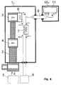
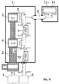
- FIGS. 4 and 5 The current state of the art for cryogenic devices for cooling NMR receiving coils is shown in FIGS. 4 and 5 shown. Both cooling devices allow cooling the receiving coil to a temperature below 30 K. A in contrast, improved arrangement in which both the receiving coil like the preamplifier to different ones Temperatures can be cooled is in Fig. 6 shown.
- FIG. 4 she consists from a cooling device 1e, the inner part of which is evacuated is about thermal loss due to heat conduction to avoid the air.
- the cooling is done by a cryo cooler 2, which is connected to a compressor 5 via gas lines and from a first cooling stage 4 to 20 K and one second cooling stage 3 is composed to 22 K. Both levels represent cold sources and have thermal tapping areas, connected to the individual parts and cooled can be.
- a stage exchanger 8 which is connected to the second cooling stage 3 of the cryo cooler 2 is.
- the pump 6 is a circulating pump that the helium gas in one circulates in a closed circuit.
- the helium gas joins Room temperature (300 K) from the pump to the cooling device a, where it is through a counterflow exchanger 7 to 40 K. is pre-cooled.
- the helium gas is then in the stage exchanger 8, which is connected to the second stage 3 of the cryo cooler is cooled to 22 K.
- This helium gas is over a transfer line 9 of a receiving coil 11 in an NMR measuring head 10e supplied, whereby the receiving coil 11 on 27 K is cooled.
- the helium gas heats up to 27 K. and passes through the transfer line 9 back into the cooling device 1e back. There it gets back into the counterflow exchanger 7 where it warms up to 287 K and practical gets back to the pump at room temperature.
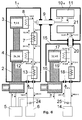
- FIG. 5 also shows a known arrangement (approximately equivalent to U.S. Patent 5,508,613) which has improved efficiency.
- the cryo-cooler 2 of the cooling device 1f also has a first stage 4 for cooling the helium gas and for this purpose requires two counterflow exchangers 13 and 7.
- the second stage 3 can deliver cooler gas, ie more cooling power, to the receiving coil 11 in the NMR measuring head 10f.
- the entering helium gas which is at room temperature, is first opened using the first counterflow exchanger 13 38.8 K and then in a stage exchanger 12 of the first stage 4 of the Cryo-Cooler 2 to 26.3 K before cooling it to second counterflow exchanger 7 arrives.
- This cold gas is the transfer line 9 of the receiving coil 11 fed, bringing this down to 14.6 K. is cooled.
- the heated to 14.6 K Gas again via the transfer line 9 into the cooling device 1f and back via the counterflow exchanger 7 and 13 to the pump 6.
- the entering and exiting helium gas the pump 6 have approximately the same temperatures, which on make good use of the refrigeration capacity of the gas leaves.
- Fig. 6 illustrates a cooling device that both the receiving coil 11 as well as a preamplifier 21 in the NMR measuring head 10g can cool down to two different ones Temperature ranges, namely less than 20 K and about 77 K.
- two Cryo-Cooler 2 and 16 and two separate cooling circuits used, a first one for the receiving coil and driven by the pump 6, a second for the preamplifier and driven by a pump 14.
- the first cooling circuit is through the already known cooling device 5 cooled and has a standard flow of 55 normal liters / min on, which is set with a valve 24 and is labeled 100% in FIG. 6.
- the second cooling circuit is only cooled by a one-stage cryo cooler 16, and its mass flow is adjusted with a valve 25 so that the preamplifier 21 the desired temperature of 77 K reached.
- the mass flow required for this is then 45% of the norm flow and is also entered in FIG. 6.
- the cooling device 1g is identical to that described in FIG. 5 known device and requires no further Explanations.
- the additional cooling device 15 in Fig. 6 is the helium gas that the pump 14 at room temperature leaves, in a counterflow exchanger 18 to 87.6 K. pre-cooled and then in a stage exchanger 19, the with the first and only cooling stage 17 of the cryo cooler 16 is cooled to 32.4 K.
- the helium gas cooled in this way reaches the NMR measuring head 10g via a transfer line 20 and to the preamplifier 21, which is cooled to 77 K.
- two coil systems or resonators which are arranged orthogonally to one another, are normally installed in the area of the measurement sample, which can serve both to excite the spin system and to receive the NMR signal.
- Both coil systems or resonators are usually tuned to different types of nuclei, e.g. one coil system to protons 1 H and the other to phosphorus 31 P.
- each of the two coil systems or resonators can be tuned to two or more types of nuclei at the same time, which allows a variety of measurement options . If the description below refers to a receiving coil 11, then it is meant such coil systems or resonators as have just been described.
- NMR signals from several Nuclear species can be received at the same time. These NMR signals are generally in different frequency ranges and therefore need different preamplifiers. So if in the further description of a preamplifier 21 then several preamplifiers should be used at the same time be meant.
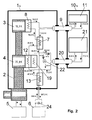
- the three devices differ essentially by the way the preamp on temperature cooled from 77 K.
- the first device is shown in FIG. 1.
- she uses for cooling the preamplifier 21 a second, separate one Helium gas cycle.
- the first cycle is the Cooling of the receiving coil 11 and is driven by the pump 6.
- the second is driven by the pump 14 and cools the preamplifier 21.
- the first cooling stage 4 of the Cryo-Coolers 2 not only cooling the first circuit, but also the second. That way it is possible to get by with only one Cryo-Cooler 2 and, compared to Fig. 6, with much less equipment Expenditure.
- the description of the first cycle can be 5 that of the second Circuit of that of FIG. 6.
- the valve 24 serves to open the gas flow in the cooling device 1b set the assumed norm flow.
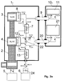
- the third cooling device gives the best results and is shown in Fig. 3a.
- this device is in Gas return the connection from the counterflow exchanger 7 to the counterflow exchanger 13 interrupted and a cooling connection produced via the transfer line 20 to the preamplifier 21. In this way, the stage exchanger 19 from FIG. 2 no longer needed.
- This cooling device comes with the minimum number of components, provides the best results compared to the other two proposals and also leads to a reduction in overall costs.
- the valve 22 can, similar to the device 2, adjust the gas flow to the preamplifier 21 in such a way that the preamplifier 21 is cooled to 77 K.
- the amount of gas required for this is 47% of the total flow and has a temperature of 34.4 K. This gas heats up in this cooling process from 34.4 K to 77 K, flows over the Transfer line 20 back into the cooling device 1c, mixes with the gas from valve 22, being a Temperature of 54.4 K, and then reaches the Counterflow exchanger 13 and then back to the pump 6.
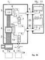
- the valve 22 serves the cooling capacity, which is led to the preamplifier 21 via the helium gas, so set that the 20 W that the preamplifier 21 generates be dissipated and the desired temperature of 77 K is reached. But you can also do without the valve and the full cooling capacity of the gas to the preamplifier 21 lead. Without countermeasures, the preamplifier would 21 cooling down too much and temperatures below Reach 77 K. But this can be avoided by a heater 23 is attached to the housing of the preamplifier 21 with which the preamplifier is returned to the desired Temperature of 77 K can be heated. 3b is shown a cooling device in which such a heater 23 is used.
- the heater has the disadvantage that the first stage 4 of the cryo cooler 2 is more stressed and this also slightly affects the second stage 3.
- the temperature at the output of the stage exchanger 8 therefore rises from 10.0 K (see Fig. 3a) to 10.3 K (see Fig. 3b).
- a heater 23 is not only the inventive Arrangement limited in Fig. 3b. It can too in the two other arrangements according to the invention in the Figures 1 and 2 are used.
Landscapes
- Physics & Mathematics (AREA)
- Condensed Matter Physics & Semiconductors (AREA)
- General Physics & Mathematics (AREA)
- Thermal Sciences (AREA)
- Sampling And Sample Adjustment (AREA)
Applications Claiming Priority (2)
| Application Number | Priority Date | Filing Date | Title |
|---|---|---|---|
| DE19720677A DE19720677C1 (de) | 1997-05-16 | 1997-05-16 | NMR-Meßvorrichtung mit gekühltem Meßkopf |
| DE19720677 | 1997-05-16 |
Publications (2)
| Publication Number | Publication Date |
|---|---|
| EP0878718A1 true EP0878718A1 (fr) | 1998-11-18 |
| EP0878718B1 EP0878718B1 (fr) | 2004-09-15 |
Family
ID=7829731
Family Applications (1)
| Application Number | Title | Priority Date | Filing Date |
|---|---|---|---|
| EP98107241A Expired - Lifetime EP0878718B1 (fr) | 1997-05-16 | 1998-04-21 | Dispositif de mesure pour la RMN avec tête de mesure refroidie |
Country Status (4)
| Country | Link |
|---|---|
| US (1) | US5889456A (fr) |
| EP (1) | EP0878718B1 (fr) |
| JP (1) | JP2947348B2 (fr) |
| DE (2) | DE19720677C1 (fr) |
Cited By (5)
| Publication number | Priority date | Publication date | Assignee | Title |
|---|---|---|---|---|
| EP1512983A1 (fr) * | 2003-09-02 | 2005-03-09 | Bruker BioSpin AG | Tête RMN réfrigérée avec des échangeurs de chaleur séparés pour le refroidissement des bobines de détection et d'émission ou de découplage |
| EP1655616A1 (fr) * | 2004-11-09 | 2006-05-10 | Bruker BioSpin AG | Spectromètre à RMN avec refroidissement par réfrigérateur |
| EP1760480A1 (fr) * | 2005-09-01 | 2007-03-07 | Bruker BioSpin AG | Appareil RMN muni d'une tête de sonde et d'un conteneur cryogénique refroidis ensemble |
| EP2068103A2 (fr) | 2007-12-05 | 2009-06-10 | Bruker BioSpin AG | Module de mesure destiné à la mesure rapide de composants électriques, électroniques et mécaniques à des températures cryogènes et dispositif de mesure doté d'un tel module de mesure |
| CN105228896A (zh) * | 2012-11-12 | 2016-01-06 | 托奇多有限责任公司 | 具有电力驱动和紧急停止开关的船 |
Families Citing this family (41)
| Publication number | Priority date | Publication date | Assignee | Title |
|---|---|---|---|---|
| DE19946371C1 (de) * | 1999-09-28 | 2001-06-13 | Bruker Ag Faellanden | Verbindungskonzept zwischen Kryokühlsystemen und gekühlten NMR-Probenköpfen in einer NMR-Meßvorrichtung mit Kühlanlage und Transferleitung |
| US6289681B1 (en) * | 1999-11-17 | 2001-09-18 | General Electric Company | Superconducting magnet split cryostat interconnect assembly |
| DE10006323C1 (de) * | 2000-02-12 | 2001-08-09 | Bruker Ag Faellanden | Gekühlter NMR-Probenkopf mit gleichmäßiger Temperierung der Meßprobe |
| DE10006324C1 (de) * | 2000-02-12 | 2001-08-16 | Bruker Ag Faellanden | Gekühlter NMR-Probenkopf mit Vorrichtung zur Zentrierung der Meßprobe |
| GB0014715D0 (en) * | 2000-06-15 | 2000-08-09 | Cryogenic Ltd | Method and apparatus for providing a variable temperature sample space |
| DE10040231A1 (de) * | 2000-08-17 | 2002-02-28 | Siemens Ag | Kurzschluss-Schutzsystem für Schiffe |
| WO2002057693A1 (fr) * | 2001-01-17 | 2002-07-25 | Sierra Lobo, Inc. | Densificateur pour le conditionnement simultane de deux liquides cryogeniques |
| US7347053B1 (en) | 2001-01-17 | 2008-03-25 | Sierra Lobo, Inc. | Densifier for simultaneous conditioning of two cryogenic liquids |
| AU2002322345A1 (en) * | 2001-06-28 | 2003-03-03 | The Trustees Of The University Of Pennsylania | Joule-thomson micro-refrigerator-cooled radio-frequency coils as detectors for imaging systems |
| JP4133777B2 (ja) | 2003-01-06 | 2008-08-13 | 日本電子株式会社 | 核磁気共鳴プローブ |
| JP4150825B2 (ja) * | 2003-03-31 | 2008-09-17 | 独立行政法人理化学研究所 | Nmrプローブ |
| US7112963B2 (en) * | 2003-04-11 | 2006-09-26 | Jeol Ltd. | NMR measurement method |
| JP4034253B2 (ja) * | 2003-09-30 | 2008-01-16 | 株式会社日立製作所 | 核磁気共鳴測定装置 |
| GB0408312D0 (en) * | 2004-04-14 | 2004-05-19 | Oxford Instr Superconductivity | Cooling apparatus |
| DE102004053972B3 (de) * | 2004-11-09 | 2006-07-20 | Bruker Biospin Gmbh | NMR-Spektrometer mit gemeinsamen Refrigerator zum Kühlen von NMR-Probenkopf und Kryostat |
| DE102004060832B3 (de) * | 2004-12-17 | 2006-06-14 | Bruker Biospin Gmbh | NMR-Spektrometer mit gemeinsamen Refrigerator zum Kühlen von NMR-Probenkopf und Kryostat |
| US7167000B2 (en) * | 2004-12-22 | 2007-01-23 | General Electric Company | Cryogenically cooled radiofrequency coil array for magnetic resonance imaging |
| JP4309854B2 (ja) * | 2005-01-20 | 2009-08-05 | 株式会社日立製作所 | 低温プローブ及びそれを用いた核磁気共鳴分析装置 |
| US7481375B2 (en) * | 2005-03-04 | 2009-01-27 | Honeywell International Inc. | Apparatuses and methods for controlling the temperature of a process fluid |
| US7309987B2 (en) * | 2005-10-28 | 2007-12-18 | Varian, Inc. | Anticipative temperature regulation of cryogenic NMR probes |
| DE102006011254B4 (de) * | 2006-03-10 | 2009-01-29 | Siemens Ag | Magnetresonanzanlage mit supraleitender Ganzkörper-Empfangsanordnung |
| DE102006020772B3 (de) * | 2006-05-03 | 2007-11-29 | Bruker Biospin Ag | Gekühlter NMR Probenkopf mit flexibler gekühlter Verbindungsleitung |
| DE102006020774B3 (de) * | 2006-05-03 | 2008-02-07 | Bruker Biospin Ag | Gekühlter, kuppelbarer NMR-Probenkopf |
| US7378848B2 (en) * | 2006-05-05 | 2008-05-27 | M2M Imaging Corp. | Magnetic resonance coil system |
| JP4641297B2 (ja) * | 2006-09-19 | 2011-03-02 | 株式会社日立製作所 | 極低温冷却システム |
| DE102006051880A1 (de) * | 2006-10-31 | 2008-05-08 | Linde Ag | Verfahren zum Abkühlen supraleitender Magnete |
| JP4938423B2 (ja) * | 2006-11-24 | 2012-05-23 | 株式会社日立製作所 | 核磁気共鳴プローブ |
| CN201107673Y (zh) * | 2007-09-19 | 2008-08-27 | 西门子(中国)有限公司 | 磁体温度控制装置 |
| US20100267567A1 (en) * | 2007-12-10 | 2010-10-21 | Koninklijke Philips Electronics N.V. | Superconducting magnet system with cooling system |
| EP2310768B1 (fr) * | 2008-05-21 | 2018-12-26 | Brooks Automation, Inc. | Réfrigérateur cryogénique à entraînement linéaire |
| US8516834B2 (en) * | 2008-08-14 | 2013-08-27 | S2 Corporation | Apparatus and methods for improving vibration isolation, thermal dampening, and optical access in cryogenic refrigerators |
| TWI571941B (zh) | 2010-05-12 | 2017-02-21 | 布魯克機械公司 | 用於低溫冷卻的系統及方法 |
| DE102011006164B8 (de) | 2011-03-25 | 2013-04-18 | Bruker Biospin Ag | Kompakter kryogener NMR-Sensor mit integriertem, aktivem Kühlaggregat |
| US9574685B2 (en) * | 2012-06-19 | 2017-02-21 | Pittsburgh Universal, LLC | Cooling system for magnetic resonance imaging device having reduced noise and vibration |
| US20150300719A1 (en) * | 2014-04-16 | 2015-10-22 | Victoria Link Ltd | Cryogenic gas circulation and heat exchanger |
| US10775285B1 (en) | 2016-03-11 | 2020-09-15 | Montana Intruments Corporation | Instrumental analysis systems and methods |
| US11125663B1 (en) | 2016-03-11 | 2021-09-21 | Montana Instruments Corporation | Cryogenic systems and methods |
| EP3285032B1 (fr) | 2016-08-18 | 2019-07-24 | Bruker BioSpin AG | Agencement de cryostat et son procédé de fonctionnement |
| JP6975019B2 (ja) * | 2017-10-27 | 2021-12-01 | 住友重機械工業株式会社 | 極低温システム |
| WO2020076988A1 (fr) | 2018-10-09 | 2020-04-16 | Montana Instruments Corporation | Ensembles et procédés cryoréfrigérateurs |
| US11956924B1 (en) | 2020-08-10 | 2024-04-09 | Montana Instruments Corporation | Quantum processing circuitry cooling systems and methods |
Citations (3)
| Publication number | Priority date | Publication date | Assignee | Title |
|---|---|---|---|---|
| EP0453834A1 (fr) * | 1990-04-25 | 1991-10-30 | Spectrospin Ag | Dispositif de bobines de réception HF pour spectromètres RMN |
| US5508613A (en) * | 1994-08-29 | 1996-04-16 | Conductus, Inc. | Apparatus for cooling NMR coils |
| EP0782005A1 (fr) * | 1995-12-20 | 1997-07-02 | Spectrospin Ag | Tête d'échantillon pour un spectromètre RMN |
Family Cites Families (2)
| Publication number | Priority date | Publication date | Assignee | Title |
|---|---|---|---|---|
| US4279127A (en) * | 1979-03-02 | 1981-07-21 | Air Products And Chemicals, Inc. | Removable refrigerator for maintaining liquefied gas inventory |
| US4277949A (en) * | 1979-06-22 | 1981-07-14 | Air Products And Chemicals, Inc. | Cryostat with serviceable refrigerator |
-
1997
- 1997-05-16 DE DE19720677A patent/DE19720677C1/de not_active Expired - Lifetime
-
1998
- 1998-03-27 US US09/049,196 patent/US5889456A/en not_active Expired - Lifetime
- 1998-04-21 EP EP98107241A patent/EP0878718B1/fr not_active Expired - Lifetime
- 1998-04-21 DE DE59811936T patent/DE59811936D1/de not_active Expired - Lifetime
- 1998-05-18 JP JP10151927A patent/JP2947348B2/ja not_active Expired - Fee Related
Patent Citations (3)
| Publication number | Priority date | Publication date | Assignee | Title |
|---|---|---|---|---|
| EP0453834A1 (fr) * | 1990-04-25 | 1991-10-30 | Spectrospin Ag | Dispositif de bobines de réception HF pour spectromètres RMN |
| US5508613A (en) * | 1994-08-29 | 1996-04-16 | Conductus, Inc. | Apparatus for cooling NMR coils |
| EP0782005A1 (fr) * | 1995-12-20 | 1997-07-02 | Spectrospin Ag | Tête d'échantillon pour un spectromètre RMN |
Cited By (9)
| Publication number | Priority date | Publication date | Assignee | Title |
|---|---|---|---|---|
| EP1512983A1 (fr) * | 2003-09-02 | 2005-03-09 | Bruker BioSpin AG | Tête RMN réfrigérée avec des échangeurs de chaleur séparés pour le refroidissement des bobines de détection et d'émission ou de découplage |
| EP1655616A1 (fr) * | 2004-11-09 | 2006-05-10 | Bruker BioSpin AG | Spectromètre à RMN avec refroidissement par réfrigérateur |
| EP1760480A1 (fr) * | 2005-09-01 | 2007-03-07 | Bruker BioSpin AG | Appareil RMN muni d'une tête de sonde et d'un conteneur cryogénique refroidis ensemble |
| EP2068103A2 (fr) | 2007-12-05 | 2009-06-10 | Bruker BioSpin AG | Module de mesure destiné à la mesure rapide de composants électriques, électroniques et mécaniques à des températures cryogènes et dispositif de mesure doté d'un tel module de mesure |
| DE102007055712A1 (de) | 2007-12-05 | 2009-06-18 | Bruker Biospin Ag | Messmodul zur schnellen Messung von elektrischen, elektronischen und mechanischen Bauteilen bei kryogenen Temperaturen sowie Messeinrichtung mit einem solchen Messmodul |
| CN105228896A (zh) * | 2012-11-12 | 2016-01-06 | 托奇多有限责任公司 | 具有电力驱动和紧急停止开关的船 |
| US9789946B2 (en) | 2012-11-12 | 2017-10-17 | Torqeedo Gmbh | Boat with electric drive and emergency off switch |
| CN105228896B (zh) * | 2012-11-12 | 2018-01-05 | 托奇多有限责任公司 | 具有电力驱动和紧急停止开关的船 |
| US10392095B2 (en) | 2012-11-12 | 2019-08-27 | Torqeedo Gmbh | Electric drive and emergency stop switch for boats |
Also Published As
| Publication number | Publication date |
|---|---|
| DE19720677C1 (de) | 1998-10-22 |
| US5889456A (en) | 1999-03-30 |
| DE59811936D1 (de) | 2004-10-21 |
| EP0878718B1 (fr) | 2004-09-15 |
| JP2947348B2 (ja) | 1999-09-13 |
| JPH10332801A (ja) | 1998-12-18 |
Similar Documents
| Publication | Publication Date | Title |
|---|---|---|
| EP0878718B1 (fr) | Dispositif de mesure pour la RMN avec tête de mesure refroidie | |
| EP1655616B1 (fr) | Spectromètre à RMN avec refroidissement par réfrigérateur | |
| DE102004053972B3 (de) | NMR-Spektrometer mit gemeinsamen Refrigerator zum Kühlen von NMR-Probenkopf und Kryostat | |
| DE69838866T2 (de) | Verbesserungen in oder mit Bezug auf Kryostatsystemen | |
| EP1504458B1 (fr) | Dispositif de supraconductivite comportant un aimant supraconducteur et une unite de refroidissement | |
| EP1512983B1 (fr) | Tête RMN réfrigérée avec des échangeurs de chaleur séparés pour le refroidissement des bobines de détection et d'émission ou de découplage | |
| EP3285032B1 (fr) | Agencement de cryostat et son procédé de fonctionnement | |
| DE4013111C2 (de) | HF-Empfangsspulenanordnung für NMR-Spektrometer | |
| DE102005041383B4 (de) | NMR-Apparatur mit gemeinsam gekühltem Probenkopf und Kryobehälter und Verfahren zum Betrieb derselben | |
| DE19648253C2 (de) | Pulsröhrenkühler und Verwendung desselben | |
| EP3282270B1 (fr) | Appareil rmn pourvu d'un système d'aimants supraconducteurs et composants formant sondes refroidis | |
| DE102005028414B4 (de) | Einrichtung zur Erzeugung eines gepulsten Magnetfelds | |
| DE102004060832B3 (de) | NMR-Spektrometer mit gemeinsamen Refrigerator zum Kühlen von NMR-Probenkopf und Kryostat | |
| DE112011100875T5 (de) | Verfahren und Vorrichtung zum Regeln der Temperatur in einem auf tiefe Temperaturen gekühlten Kyrostaten unter Verwendung von stehendem und sich bewegendem Gas | |
| DE19914778A1 (de) | Supraleitende Magnetvorrichtung | |
| DE102004037172A1 (de) | Kryostatanordnung | |
| DE102014009568A1 (de) | Supraleitende Magnetvorrichtung | |
| DE69310755T2 (de) | Magnetischer sensor und magnetischer detektor | |
| EP2068103A2 (fr) | Module de mesure destiné à la mesure rapide de composants électriques, électroniques et mécaniques à des températures cryogènes et dispositif de mesure doté d'un tel module de mesure | |
| DE69211237T2 (de) | Vakuumbehälter mit einem gekühlten Element | |
| EP1089086B1 (fr) | Concept de raccord entre sytèmes de refroidissement cryogéniques et têtes de mesure RMN | |
| EP2320244A1 (fr) | Dispositif de refroidissement pour le refroidissement cryogène d'un système de détection RMN à l'aide d'un récipient rempli de fluide cryogène | |
| DE102004034729B4 (de) | Kryostatanordnung mit Kryokühler und Gasspaltwärmeübertrager | |
| EP0212093B1 (fr) | Procédé pour refroidir un objet à l'aide d'hélium superfluide (HeII) et dispositif pour la mise en oeuvre du procédé | |
| EP3244137A1 (fr) | Système magnétique non cryogénique doté d'un puits thermique magnéto-calorique |
Legal Events
| Date | Code | Title | Description |
|---|---|---|---|
| PUAI | Public reference made under article 153(3) epc to a published international application that has entered the european phase |
Free format text: ORIGINAL CODE: 0009012 |
|
| 17P | Request for examination filed |
Effective date: 19980821 |
|
| AK | Designated contracting states |
Kind code of ref document: A1 Designated state(s): CH DE FR GB LI |
|
| AX | Request for extension of the european patent |
Free format text: AL;LT;LV;MK;RO;SI |
|
| RAP1 | Party data changed (applicant data changed or rights of an application transferred) |
Owner name: BRUKER AG |
|
| AKX | Designation fees paid |
Free format text: CH DE FR GB LI |
|
| RAP1 | Party data changed (applicant data changed or rights of an application transferred) |
Owner name: BRUKER BIOSPIN AG |
|
| GRAP | Despatch of communication of intention to grant a patent |
Free format text: ORIGINAL CODE: EPIDOSNIGR1 |
|
| GRAS | Grant fee paid |
Free format text: ORIGINAL CODE: EPIDOSNIGR3 |
|
| GRAA | (expected) grant |
Free format text: ORIGINAL CODE: 0009210 |
|
| AK | Designated contracting states |
Kind code of ref document: B1 Designated state(s): CH DE FR GB LI |
|
| REG | Reference to a national code |
Ref country code: GB Ref legal event code: FG4D Free format text: NOT ENGLISH Ref country code: CH Ref legal event code: EP |
|
| REF | Corresponds to: |
Ref document number: 59811936 Country of ref document: DE Date of ref document: 20041021 Kind code of ref document: P |
|
| GBT | Gb: translation of ep patent filed (gb section 77(6)(a)/1977) |
Effective date: 20050124 |
|
| ET | Fr: translation filed | ||
| PLBE | No opposition filed within time limit |
Free format text: ORIGINAL CODE: 0009261 |
|
| STAA | Information on the status of an ep patent application or granted ep patent |
Free format text: STATUS: NO OPPOSITION FILED WITHIN TIME LIMIT |
|
| 26N | No opposition filed |
Effective date: 20050616 |
|
| PGFP | Annual fee paid to national office [announced via postgrant information from national office to epo] |
Ref country code: GB Payment date: 20140423 Year of fee payment: 17 |
|
| PGFP | Annual fee paid to national office [announced via postgrant information from national office to epo] |
Ref country code: CH Payment date: 20140422 Year of fee payment: 17 Ref country code: FR Payment date: 20140416 Year of fee payment: 17 |
|
| REG | Reference to a national code |
Ref country code: CH Ref legal event code: PL |
|
| GBPC | Gb: european patent ceased through non-payment of renewal fee |
Effective date: 20150421 |
|
| PG25 | Lapsed in a contracting state [announced via postgrant information from national office to epo] |
Ref country code: GB Free format text: LAPSE BECAUSE OF NON-PAYMENT OF DUE FEES Effective date: 20150421 Ref country code: LI Free format text: LAPSE BECAUSE OF NON-PAYMENT OF DUE FEES Effective date: 20150430 Ref country code: CH Free format text: LAPSE BECAUSE OF NON-PAYMENT OF DUE FEES Effective date: 20150430 |
|
| REG | Reference to a national code |
Ref country code: FR Ref legal event code: ST Effective date: 20151231 |
|
| PG25 | Lapsed in a contracting state [announced via postgrant information from national office to epo] |
Ref country code: FR Free format text: LAPSE BECAUSE OF NON-PAYMENT OF DUE FEES Effective date: 20150430 |
|
| PGFP | Annual fee paid to national office [announced via postgrant information from national office to epo] |
Ref country code: DE Payment date: 20170412 Year of fee payment: 20 |
|
| REG | Reference to a national code |
Ref country code: DE Ref legal event code: R071 Ref document number: 59811936 Country of ref document: DE |