EP0878718A1 - MNR measuring device with cooled probe head - Google Patents
MNR measuring device with cooled probe head Download PDFInfo
- Publication number
- EP0878718A1 EP0878718A1 EP98107241A EP98107241A EP0878718A1 EP 0878718 A1 EP0878718 A1 EP 0878718A1 EP 98107241 A EP98107241 A EP 98107241A EP 98107241 A EP98107241 A EP 98107241A EP 0878718 A1 EP0878718 A1 EP 0878718A1
- Authority
- EP
- European Patent Office
- Prior art keywords
- cooling
- exchanger
- stage
- nmr
- measuring device
- Prior art date
- Legal status (The legal status is an assumption and is not a legal conclusion. Google has not performed a legal analysis and makes no representation as to the accuracy of the status listed.)
- Granted
Links
- 239000000523 sample Substances 0.000 title 1
- 238000005481 NMR spectroscopy Methods 0.000 claims abstract description 72
- 239000002826 coolant Substances 0.000 claims abstract description 34
- 238000005259 measurement Methods 0.000 claims abstract description 9
- 238000001816 cooling Methods 0.000 claims description 160
- 238000012546 transfer Methods 0.000 claims description 35
- 238000002955 isolation Methods 0.000 claims 1
- 238000011156 evaluation Methods 0.000 abstract 1
- 239000012530 fluid Substances 0.000 abstract 1
- 238000009434 installation Methods 0.000 abstract 1
- 239000004065 semiconductor Substances 0.000 abstract 1
- 239000007789 gas Substances 0.000 description 75
- 239000001307 helium Substances 0.000 description 33
- 229910052734 helium Inorganic materials 0.000 description 33
- SWQJXJOGLNCZEY-UHFFFAOYSA-N helium atom Chemical compound [He] SWQJXJOGLNCZEY-UHFFFAOYSA-N 0.000 description 32
- 238000011161 development Methods 0.000 description 5
- 241001136792 Alle Species 0.000 description 3
- 238000009413 insulation Methods 0.000 description 3
- 238000005457 optimization Methods 0.000 description 3
- 239000007788 liquid Substances 0.000 description 2
- 239000000463 material Substances 0.000 description 2
- 238000000691 measurement method Methods 0.000 description 2
- 230000035945 sensitivity Effects 0.000 description 2
- OAICVXFJPJFONN-UHFFFAOYSA-N Phosphorus Chemical compound [P] OAICVXFJPJFONN-UHFFFAOYSA-N 0.000 description 1
- XUIMIQQOPSSXEZ-UHFFFAOYSA-N Silicon Chemical compound [Si] XUIMIQQOPSSXEZ-UHFFFAOYSA-N 0.000 description 1
- 230000006978 adaptation Effects 0.000 description 1
- 150000001875 compounds Chemical class 0.000 description 1
- 230000003247 decreasing effect Effects 0.000 description 1
- 238000013461 design Methods 0.000 description 1
- 238000009826 distribution Methods 0.000 description 1
- 238000005516 engineering process Methods 0.000 description 1
- 238000010438 heat treatment Methods 0.000 description 1
- 150000002371 helium Chemical class 0.000 description 1
- 238000012423 maintenance Methods 0.000 description 1
- 238000000034 method Methods 0.000 description 1
- 239000000203 mixture Substances 0.000 description 1
- 238000005086 pumping Methods 0.000 description 1
- 230000005855 radiation Effects 0.000 description 1
- 238000005057 refrigeration Methods 0.000 description 1
- 238000010079 rubber tapping Methods 0.000 description 1
- 229910052710 silicon Inorganic materials 0.000 description 1
- 239000010703 silicon Substances 0.000 description 1
- 239000007787 solid Substances 0.000 description 1
- 241000894007 species Species 0.000 description 1
- 238000012549 training Methods 0.000 description 1
Images

Classifications
-
- G—PHYSICS
- G01—MEASURING; TESTING
- G01R—MEASURING ELECTRIC VARIABLES; MEASURING MAGNETIC VARIABLES
- G01R33/00—Arrangements or instruments for measuring magnetic variables
- G01R33/20—Arrangements or instruments for measuring magnetic variables involving magnetic resonance
- G01R33/28—Details of apparatus provided for in groups G01R33/44 - G01R33/64
- G01R33/32—Excitation or detection systems, e.g. using radio frequency signals
- G01R33/34—Constructional details, e.g. resonators, specially adapted to MR
- G01R33/34015—Temperature-controlled RF coils
- G01R33/3403—Means for cooling of the RF coils, e.g. a refrigerator or a cooling vessel specially adapted for housing an RF coil
-
- G—PHYSICS
- G01—MEASURING; TESTING
- G01R—MEASURING ELECTRIC VARIABLES; MEASURING MAGNETIC VARIABLES
- G01R33/00—Arrangements or instruments for measuring magnetic variables
- G01R33/20—Arrangements or instruments for measuring magnetic variables involving magnetic resonance
- G01R33/28—Details of apparatus provided for in groups G01R33/44 - G01R33/64
- G01R33/32—Excitation or detection systems, e.g. using radio frequency signals
- G01R33/34—Constructional details, e.g. resonators, specially adapted to MR
-
- F—MECHANICAL ENGINEERING; LIGHTING; HEATING; WEAPONS; BLASTING
- F25—REFRIGERATION OR COOLING; COMBINED HEATING AND REFRIGERATION SYSTEMS; HEAT PUMP SYSTEMS; MANUFACTURE OR STORAGE OF ICE; LIQUEFACTION SOLIDIFICATION OF GASES
- F25B—REFRIGERATION MACHINES, PLANTS OR SYSTEMS; COMBINED HEATING AND REFRIGERATION SYSTEMS; HEAT PUMP SYSTEMS
- F25B9/00—Compression machines, plants or systems, in which the refrigerant is air or other gas of low boiling point
- F25B9/10—Compression machines, plants or systems, in which the refrigerant is air or other gas of low boiling point with several cooling stages
-
- F—MECHANICAL ENGINEERING; LIGHTING; HEATING; WEAPONS; BLASTING
- F25—REFRIGERATION OR COOLING; COMBINED HEATING AND REFRIGERATION SYSTEMS; HEAT PUMP SYSTEMS; MANUFACTURE OR STORAGE OF ICE; LIQUEFACTION SOLIDIFICATION OF GASES
- F25D—REFRIGERATORS; COLD ROOMS; ICE-BOXES; COOLING OR FREEZING APPARATUS NOT OTHERWISE PROVIDED FOR
- F25D19/00—Arrangement or mounting of refrigeration units with respect to devices or objects to be refrigerated, e.g. infrared detectors
- F25D19/006—Thermal coupling structure or interface
-
- G—PHYSICS
- G01—MEASURING; TESTING
- G01R—MEASURING ELECTRIC VARIABLES; MEASURING MAGNETIC VARIABLES
- G01R33/00—Arrangements or instruments for measuring magnetic variables
- G01R33/20—Arrangements or instruments for measuring magnetic variables involving magnetic resonance
- G01R33/28—Details of apparatus provided for in groups G01R33/44 - G01R33/64
- G01R33/32—Excitation or detection systems, e.g. using radio frequency signals
- G01R33/34—Constructional details, e.g. resonators, specially adapted to MR
- G01R33/34015—Temperature-controlled RF coils
- G01R33/34023—Superconducting RF coils
-
- Y—GENERAL TAGGING OF NEW TECHNOLOGICAL DEVELOPMENTS; GENERAL TAGGING OF CROSS-SECTIONAL TECHNOLOGIES SPANNING OVER SEVERAL SECTIONS OF THE IPC; TECHNICAL SUBJECTS COVERED BY FORMER USPC CROSS-REFERENCE ART COLLECTIONS [XRACs] AND DIGESTS
- Y10—TECHNICAL SUBJECTS COVERED BY FORMER USPC
- Y10S—TECHNICAL SUBJECTS COVERED BY FORMER USPC CROSS-REFERENCE ART COLLECTIONS [XRACs] AND DIGESTS
- Y10S505/00—Superconductor technology: apparatus, material, process
- Y10S505/825—Apparatus per se, device per se, or process of making or operating same
- Y10S505/888—Refrigeration
- Y10S505/892—Magnetic device cooling
Definitions
- the invention relates to a measuring device for nuclear magnetic resonance (NMR) measurements with one or more NMR receiving coils containing NMR measuring head, which has a cryotechnical insulated transfer line with coolant from a Cooling device can be supplied, the cooling device a cryo cooler with a first cooling stage with one first stage exchanger and with a second cooling stage has a second stage exchanger, wherein a pump is provided is that in a circuit initially at room temperature located coolant through a first counterflow exchanger, the first stage exchanger, a second counterflow exchanger, the second stage exchanger and the transfer line into the NMR measuring head for cooling the NMR receiving coil (s) and back through the transfer line, the second counterflow exchanger and the first counterflow exchanger can promote.
- NMR nuclear magnetic resonance
- NMR spectroscopy is a measurement method with which the Structure of chemical compounds determined very precisely can be. This advantage is a major disadvantage contrary: NMR spectroscopy is unfortunately also a very insensitive measurement method, which is generally only a very small signal-to-noise ratio (S / N ratio) delivers. It is therefore necessary to consider all the possibilities may lead to an increase in sensitivity to draw.
- receiving coil is not only intended to be pure inductances be meant, but also resonators, both from distributed inductors as well as distributed capacities are composed and in this way a resonant Represent structures in the high frequency range.
- the S / N ratio of the NMR signal at the output of the receiver is primarily limited by the S / N ratio of the receiving coil.
- This S / N ratio depends on how large the NMR signal received from a standard sample is compared to the intrinsic noise of the coil.
- the size of the NMR signal depends on the geometry of the receiving coil and how tightly the coil encloses the measurement sample. These properties cannot be influenced by the temperature.
- the situation is different with the intrinsic noise of the coil, which is generated by the high-frequency loss resistance R HF of the coil and firstly depends on the size of its resistance value R HF and secondly on its temperature T, more precisely on the root of the product R HF ⁇ T.
- both its resistance value R HF and its temperature T are reduced, so that both together lead to a considerable reduction in self-noise and a corresponding increase in the S / N ratio.
- NMR measuring device is from US Pat. No. 5,508,613 cited at the beginning known with cooled NMR receiving coil.
- Another one, problem not solved with the known device consists, however, in the self-noise of the preamplifier, which is the amplify NMR signals coming from the NMR reception coil should and usually works at room temperature.
- the object of the present invention is therefore an NMR measuring device of the type described at the beginning, with the simplest possible means and without large ones technical effort also a significant reduction in noise is achieved with the preamplifier.
- this object is achieved in that NMR measuring head in addition to the NMR receiving coil or coils one or more preamplifiers to amplify the NMR reception coils received NMR signals are present, that another cryogenically isolated transfer line provided between the cooling device and the NMR measuring head over which the preamplifier (s) and / or with the Preamplifiers related components, e.g. Radio frequency (RF) switch, RF filters, fasteners and the like, are supplied with a coolant flow which is at a higher temperature level than the coolant flow used to cool the NMR receiving coils, and that only for cooling both coolant flows the cryo-cooler and possibly other heat exchangers are provided.
- RF Radio frequency
- cryo cooler is understood to mean a device which has a cooling surface for cooling objects provides and is operated with cryogenic media, for example a cooler after Gifford-McMahon, a pulse-tube cooler or a Joule-Thomson refrigerator.
- Cooling the preamplifier to reduce noise should not be done to much below 80 K because otherwise the electronic components made in silicon technology are made, lose their functionality. Fortunately, the preamp noise is too at this somewhat elevated temperature it is still so small that it no longer dominates over the noise of the receiving coil.
- An embodiment of the invention is therefore advantageous Measuring device in which the first coolant flow immediately after leaving the NMR receiving coils Temperature below 20 K, preferably around 15 K, and the second coolant flow immediately after leaving the preamplifier a temperature around 80 K, preferably about 77 K. having.
- the NMR receiving coils can in principle can also be cooled to lower temperatures, however a significantly higher technical effort in particular would require the cryo cooler, which is not acceptable in any Relationship to the achievable improvement would be more.
- Measuring device are two separate cooling circuits for cooling the NMR receiving coils on the one hand and for cooling the Preamplifier and / or related components otherwise provided.
- Advantageous in this embodiment is that no cooled valves are required are.
- a further development of this embodiment provides that in addition for the first stage exchanger, another stage exchanger connected to the first cooling stage of the cryo cooler is, the first stage exchanger for cooling the coolant flow in the cooling circuit of the NMR receiving coils and further stage exchangers in the cooling circuit of the preamplifiers is inserted.
- another stage changer at the first cooling stage there is a spatial one compact solution.
- each at least one to approximately room temperature located valve for controlling the mass flows of the coolant is provided.
- the room temperature valve serves the fine optimization of the coolant flows and thus the Temperature distributions in the two cooling circuits.
- An embodiment of the invention is particularly preferred Measuring device in which only a single cooling circuit with two partial flows for cooling the NMR reception coils on the one hand and for cooling the preamplifier and / or related components provided on the other hand is. Compared to the embodiment described above with two separate cooling circuits are less expensive cryo components required, since at least one counterflow exchanger as a cold buffer for the second cooling circuit falls away.
- this embodiment is a cooled valve to control the mass flow of the coolant flowing to the preamplifiers.
- a cooled valve to control the mass flow of the coolant flowing to the preamplifiers.
- Step exchanger connected to the first cooling stage of the cryo cooler is, with the further stage exchanger for cooling the preamplifier and / or related to it Components and possibly one for the first stage exchanger direct flowing partial flow of coolant and the first Step exchanger for cooling the to the NMR receiving coils flowing coolant is used.
- the further Step exchanger is a first pre-cooling of the coolant causes. The coolant heated in the preamplifiers becomes then again to the first stage of the cryo cooler and cooled with the first stage exchanger, making an improvement the cooling efficiency of the second counterflow exchanger and thus a reduction in the load on the second cooling stage of the cryo cooler is reached.
- Embodiment becomes a partial stream of that of the NMR receiving coils flowing back over the second counterflow exchanger Coolant for cooling the preamplifier and / or thus in Branch of connected components and then through the further transfer line and the first counterflow exchanger returned to the pump.
- Coolant for cooling the preamplifier and / or thus in Branch of connected components and then through the further transfer line and the first counterflow exchanger returned to the pump.
- the entire coolant flow can also be used from the NMR receiving coils via the second counterflow exchanger for cooling the preamplifier and / or in connection with it standing components and then through the others Transfer line and the first counterflow exchanger for Pump.
- this solution is the simplest and most compact with high efficiency. A a cooled valve is not required.
- Measuring device is in close proximity to the preamplifier Heater provided with which a simple direct Temperature control of the preamplifier can be made can.
- a temperature between 300 K and the temperature of the receiving coil is available because this can be used as a support can be used to attach the receiver coil. Thereby there is no need to support components at room temperature, and you get a significant reduction the heat flow through the mounting structure of the receiving coil. As a result, more solid attachments can be made and supply lines can be used without the heat flow gets too big.
- the cooled mass can e.g. with the help of the first stage of a two-stage cryo cooler keep cool.
- the cooling of a receiving coil in the area below 30 K is not easy because the coil is not very thermal can be effectively isolated.
- the coil should namely for reasons of sensitivity, enclose the measurement sample relatively closely, the latter, however, should be at room temperature stay. The coil is thus removed from the measurement sample and its environment at room temperature strongly with Radiated heat, and the resulting heat flow must from the cooling device can be included.
- cooling devices are two different Types of heat exchangers used, the stage exchanger with a single gas line, and the counterflow exchanger with two gas lines.
- the stage exchanger requires a direct thermal Connection to a cold source (e.g. one of the cooling levels of a cryo cooler) and cools it from the heat exchanger escaping gas down to the temperature of the cold source.
- a cold source e.g. one of the cooling levels of a cryo cooler
- the efficiency of this heat exchanger is greatest when the escaping gas is exactly the temperature of the cold source assumes. This ideal efficiency is also in practice actually reached!
- the counterflow exchanger is somewhat more critical and usually always shows a loss of efficiency. It generates a heat exchange between two oppositely flowing gas streams with different temperatures and achieves this through a close thermal connection between the two gas lines.
- the efficiency of the counterflow exchanger depends on how much of the maximum transferable cooling capacity is actually transferred from the colder gas to the warmer gas. It is greatest when the temperature difference ⁇ T of the two gas flows, measured at the two ends of the heat exchanger, is zero.
- Countercurrent exchangers are used when the temperature of a cold gas flow must be increased while doing so as little as possible of the cooling energy contained in the gas (physically defined by the enthalpy) should.
- the counterflow exchanger solves this problem by: the cooling energy contained in the colder gas flow to the warmer one Transfers gas.
- FIGS. 4 and 5 The current state of the art for cryogenic devices for cooling NMR receiving coils is shown in FIGS. 4 and 5 shown. Both cooling devices allow cooling the receiving coil to a temperature below 30 K. A in contrast, improved arrangement in which both the receiving coil like the preamplifier to different ones Temperatures can be cooled is in Fig. 6 shown.
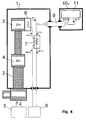
- FIG. 4 she consists from a cooling device 1e, the inner part of which is evacuated is about thermal loss due to heat conduction to avoid the air.
- the cooling is done by a cryo cooler 2, which is connected to a compressor 5 via gas lines and from a first cooling stage 4 to 20 K and one second cooling stage 3 is composed to 22 K. Both levels represent cold sources and have thermal tapping areas, connected to the individual parts and cooled can be.
- a stage exchanger 8 which is connected to the second cooling stage 3 of the cryo cooler 2 is.
- the pump 6 is a circulating pump that the helium gas in one circulates in a closed circuit.
- the helium gas joins Room temperature (300 K) from the pump to the cooling device a, where it is through a counterflow exchanger 7 to 40 K. is pre-cooled.
- the helium gas is then in the stage exchanger 8, which is connected to the second stage 3 of the cryo cooler is cooled to 22 K.
- This helium gas is over a transfer line 9 of a receiving coil 11 in an NMR measuring head 10e supplied, whereby the receiving coil 11 on 27 K is cooled.
- the helium gas heats up to 27 K. and passes through the transfer line 9 back into the cooling device 1e back. There it gets back into the counterflow exchanger 7 where it warms up to 287 K and practical gets back to the pump at room temperature.
- FIG. 5 also shows a known arrangement (approximately equivalent to U.S. Patent 5,508,613) which has improved efficiency.
- the cryo-cooler 2 of the cooling device 1f also has a first stage 4 for cooling the helium gas and for this purpose requires two counterflow exchangers 13 and 7.
- the second stage 3 can deliver cooler gas, ie more cooling power, to the receiving coil 11 in the NMR measuring head 10f.
- the entering helium gas which is at room temperature, is first opened using the first counterflow exchanger 13 38.8 K and then in a stage exchanger 12 of the first stage 4 of the Cryo-Cooler 2 to 26.3 K before cooling it to second counterflow exchanger 7 arrives.
- This cold gas is the transfer line 9 of the receiving coil 11 fed, bringing this down to 14.6 K. is cooled.
- the heated to 14.6 K Gas again via the transfer line 9 into the cooling device 1f and back via the counterflow exchanger 7 and 13 to the pump 6.
- the entering and exiting helium gas the pump 6 have approximately the same temperatures, which on make good use of the refrigeration capacity of the gas leaves.
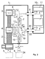
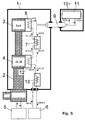
- Fig. 6 illustrates a cooling device that both the receiving coil 11 as well as a preamplifier 21 in the NMR measuring head 10g can cool down to two different ones Temperature ranges, namely less than 20 K and about 77 K.
- two Cryo-Cooler 2 and 16 and two separate cooling circuits used, a first one for the receiving coil and driven by the pump 6, a second for the preamplifier and driven by a pump 14.
- the first cooling circuit is through the already known cooling device 5 cooled and has a standard flow of 55 normal liters / min on, which is set with a valve 24 and is labeled 100% in FIG. 6.
- the second cooling circuit is only cooled by a one-stage cryo cooler 16, and its mass flow is adjusted with a valve 25 so that the preamplifier 21 the desired temperature of 77 K reached.
- the mass flow required for this is then 45% of the norm flow and is also entered in FIG. 6.
- the cooling device 1g is identical to that described in FIG. 5 known device and requires no further Explanations.
- the additional cooling device 15 in Fig. 6 is the helium gas that the pump 14 at room temperature leaves, in a counterflow exchanger 18 to 87.6 K. pre-cooled and then in a stage exchanger 19, the with the first and only cooling stage 17 of the cryo cooler 16 is cooled to 32.4 K.
- the helium gas cooled in this way reaches the NMR measuring head 10g via a transfer line 20 and to the preamplifier 21, which is cooled to 77 K.
- two coil systems or resonators which are arranged orthogonally to one another, are normally installed in the area of the measurement sample, which can serve both to excite the spin system and to receive the NMR signal.
- Both coil systems or resonators are usually tuned to different types of nuclei, e.g. one coil system to protons 1 H and the other to phosphorus 31 P.
- each of the two coil systems or resonators can be tuned to two or more types of nuclei at the same time, which allows a variety of measurement options . If the description below refers to a receiving coil 11, then it is meant such coil systems or resonators as have just been described.
- NMR signals from several Nuclear species can be received at the same time. These NMR signals are generally in different frequency ranges and therefore need different preamplifiers. So if in the further description of a preamplifier 21 then several preamplifiers should be used at the same time be meant.
- the three devices differ essentially by the way the preamp on temperature cooled from 77 K.
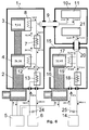
- the first device is shown in FIG. 1.
- she uses for cooling the preamplifier 21 a second, separate one Helium gas cycle.
- the first cycle is the Cooling of the receiving coil 11 and is driven by the pump 6.
- the second is driven by the pump 14 and cools the preamplifier 21.
- the first cooling stage 4 of the Cryo-Coolers 2 not only cooling the first circuit, but also the second. That way it is possible to get by with only one Cryo-Cooler 2 and, compared to Fig. 6, with much less equipment Expenditure.
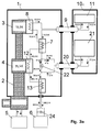
- the description of the first cycle can be 5 that of the second Circuit of that of FIG. 6.
- the valve 24 serves to open the gas flow in the cooling device 1b set the assumed norm flow.
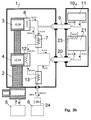
- the third cooling device gives the best results and is shown in Fig. 3a.
- this device is in Gas return the connection from the counterflow exchanger 7 to the counterflow exchanger 13 interrupted and a cooling connection produced via the transfer line 20 to the preamplifier 21. In this way, the stage exchanger 19 from FIG. 2 no longer needed.
- This cooling device comes with the minimum number of components, provides the best results compared to the other two proposals and also leads to a reduction in overall costs.
- the valve 22 can, similar to the device 2, adjust the gas flow to the preamplifier 21 in such a way that the preamplifier 21 is cooled to 77 K.
- the amount of gas required for this is 47% of the total flow and has a temperature of 34.4 K. This gas heats up in this cooling process from 34.4 K to 77 K, flows over the Transfer line 20 back into the cooling device 1c, mixes with the gas from valve 22, being a Temperature of 54.4 K, and then reaches the Counterflow exchanger 13 and then back to the pump 6.
- the valve 22 serves the cooling capacity, which is led to the preamplifier 21 via the helium gas, so set that the 20 W that the preamplifier 21 generates be dissipated and the desired temperature of 77 K is reached. But you can also do without the valve and the full cooling capacity of the gas to the preamplifier 21 lead. Without countermeasures, the preamplifier would 21 cooling down too much and temperatures below Reach 77 K. But this can be avoided by a heater 23 is attached to the housing of the preamplifier 21 with which the preamplifier is returned to the desired Temperature of 77 K can be heated. 3b is shown a cooling device in which such a heater 23 is used.
- the heater has the disadvantage that the first stage 4 of the cryo cooler 2 is more stressed and this also slightly affects the second stage 3.
- the temperature at the output of the stage exchanger 8 therefore rises from 10.0 K (see Fig. 3a) to 10.3 K (see Fig. 3b).
- a heater 23 is not only the inventive Arrangement limited in Fig. 3b. It can too in the two other arrangements according to the invention in the Figures 1 and 2 are used.
Abstract
Description
Die Erfindung betrifft eine Messvorrichtung für Kernspinresonanz(NMR)-Messungen mit einem eine oder mehrere NMR-Empfangsspulen enthaltenden NMR-Messkopf, der über eine kryotechnisch isolierte Transferleitung mit Kühlmittel aus einer Kühlvorrichtung versorgt werden kann, wobei die Kühlvorrichtung einen Cryo-Cooler mit einer ersten Kühlstufe mit einem ersten Stufentauscher und mit einer zweiten Kühlstufe mit einem zweiten Stufentauscher aufweist, wobei eine Pumpe vorgesehen ist, die in einen Kreislauf zunächst auf Zimmertemperatur befindliches Kühlmittel durch einen ersten Gegenstromtauscher, den ersten Stufentauscher, einen zweiten Gegenstromtauscher, den zweiten Stufentauscher und die Transferleitung in den NMR-Messkopf zur Kühlung der NMR-Empfangsspule(n) und wieder zurück durch die Transferleitung, den zweiten Gegenstromtauscher und den ersten Gegenstromtauscher fördern kann. The invention relates to a measuring device for nuclear magnetic resonance (NMR) measurements with one or more NMR receiving coils containing NMR measuring head, which has a cryotechnical insulated transfer line with coolant from a Cooling device can be supplied, the cooling device a cryo cooler with a first cooling stage with one first stage exchanger and with a second cooling stage has a second stage exchanger, wherein a pump is provided is that in a circuit initially at room temperature located coolant through a first counterflow exchanger, the first stage exchanger, a second counterflow exchanger, the second stage exchanger and the transfer line into the NMR measuring head for cooling the NMR receiving coil (s) and back through the transfer line, the second counterflow exchanger and the first counterflow exchanger can promote.
Eine solche NMR-Messvorrichtung ist bekannt aus der US 5,508,613.Such an NMR measuring device is known from the US 5,508,613.
Die NMR-Spektroskopie ist eine Messmethode, mit der die Struktur von chemischen Verbindungen sehr genau bestimmt werden kann. Diesem Vorteil steht aber ein grosser Nachteil entgegen: Die NMR-Spektroskopie ist leider auch eine sehr unempfindliche Messmethode, die im allgemeinen nur ein sehr kleines Signal-zu-Rausch-Verhältnis (S/N-Verhältnis) liefert. Es ist deshalb notwendig, alle Möglichkeiten, die zu einer Empfindlichkeitssteigerung führen können, in Betracht zu ziehen.NMR spectroscopy is a measurement method with which the Structure of chemical compounds determined very precisely can be. This advantage is a major disadvantage contrary: NMR spectroscopy is unfortunately also a very insensitive measurement method, which is generally only a very small signal-to-noise ratio (S / N ratio) delivers. It is therefore necessary to consider all the possibilities may lead to an increase in sensitivity to draw.
Durch Optimierung der Geometrie, durch sorgfältige Auswahl der Materialien und durch Benutzung von genau abgestimmten Materialzusammensetzungen für die NMR-Empfangsspule, konnte dieses S/N-Verhältnis beträchtlich verbessert werden. Es zeigt sich jedoch, dass wir heute an die Grenze dieser Optimierungsart gelangt sind, und dass weitere Verbesserungen nur noch in kleinen Schritten zu erwarten sind. Aus diesem Grunde war es notwendig, nach neuen Optimierungsmöglichkeiten zu suchen, auch wenn diese mit einem grösseren apparativen Aufwand verbunden sind. Eine solche Möglichkeit ist die kryogene Kühlung der Empfangsspule mit ihrem elektrischen Resonanz- und Anpassungsnetzwerk. In einem zusätzlichen Schritt muss auch der Vorverstärker gekühlt werden, damit sein Rauschen klein gegenüber dem der Empfangsspule bleibt.By optimizing the geometry, by careful selection the materials and using precisely coordinated Material compositions for the NMR receiving coil, could this S / N ratio can be improved considerably. It shows, however, that today we are at the limit of this type of optimization have come, and that further improvements can only be expected in small steps. For this Basically, it was necessary to look for new optimization options to look for, even if this with a larger apparatus Effort. One such possibility is that cryogenic cooling of the receiving coil with its electrical Resonance and adaptation network. In an additional The preamp must also be cooled step by step its noise is small compared to that of the receiving coil.
Mit dem Ausdruck "Empfangsspule" sollen nicht nur reine Induktivitäten gemeint sein, sondern auch Resonatoren, die sowohl aus verteilten Induktivitäten wie auch verteilten Kapazitäten zusammengesetzt sind und auf diese Weise ein resonanzfähiges Gebilde im Hochfrequenzbereich darstellen. The term "receiving coil" is not only intended to be pure inductances be meant, but also resonators, both from distributed inductors as well as distributed capacities are composed and in this way a resonant Represent structures in the high frequency range.
Bei den meisten NMR-Messungen wird das S/N-Verhältnis des NMR-Signals am Ausgang des Empfängers in erster Linie durch das S/N-Verhältnis der Empfangsspule limitiert. Dieses S/N-Verhältnis hängt davon ab, wie gross das von einer Standardprobe empfangene NMR-Signal im Vergleich zum Eigenrauschen der Spule ist. Die Grösse des NMR-Signals hängt von der Geometrie der Empfangsspule ab und wie eng die Spule die Messprobe umschliesst. Diese Eigenschaften können durch die Temperatur nicht beeinflusst werden. Anders verhält es sich mit dem Eigenrauschen der Spule, das durch den Hochfrequenzverlustwiderstand RHF der Spule erzeugt wird und erstens von der Grösse seines Widerstandswertes RHF und zweitens von seiner Temperatur T abhängig ist, genauer gesagt von der Wurzel des Produktes RHF·T.In most NMR measurements, the S / N ratio of the NMR signal at the output of the receiver is primarily limited by the S / N ratio of the receiving coil. This S / N ratio depends on how large the NMR signal received from a standard sample is compared to the intrinsic noise of the coil. The size of the NMR signal depends on the geometry of the receiving coil and how tightly the coil encloses the measurement sample. These properties cannot be influenced by the temperature. The situation is different with the intrinsic noise of the coil, which is generated by the high-frequency loss resistance R HF of the coil and firstly depends on the size of its resistance value R HF and secondly on its temperature T, more precisely on the root of the product R HF · T.
Durch eine Abkühlung der Empfangsspule unterhalb 30 K wird sowohl sein Widerstandswert RHF wie auch seine Temperatur T verkleinert, so dass beides zusammen zu einer beträchtlichen Verminderung des Eigenrauschens und zu einer entsprechenden Erhöhung des S/N-Verhältnisses führt.By cooling the receiving coil below 30 K, both its resistance value R HF and its temperature T are reduced, so that both together lead to a considerable reduction in self-noise and a corresponding increase in the S / N ratio.
Aus der eingangs zitierten US 5,508,613 ist eine NMR-Messvorrichtung mit abgekühlter NMR-Empfangsspule bekannt. Ein weiteres, mit der bekannten Vorrichtung nicht gelöstes Problem besteht jedoch im Eigenrauschen des Vorverstärkers, der die aus der NMR-Empfangsspule kommenden NMR-Signale verstärken soll und in der Regel bei Zimmertemperatur arbeitet.An NMR measuring device is from US Pat. No. 5,508,613 cited at the beginning known with cooled NMR receiving coil. Another one, problem not solved with the known device consists, however, in the self-noise of the preamplifier, which is the amplify NMR signals coming from the NMR reception coil should and usually works at room temperature.
Aufgabe der vorliegenden Erfindung ist es daher, eine NMR-Messvorrichtung der eingangs geschilderten Art vorzustellen, bei der mit möglichst einfachen Mitteln und ohne grossen technischen Aufwand eine erhebliche Rauschverminderung auch beim Vorverstärker erreicht wird. The object of the present invention is therefore an NMR measuring device of the type described at the beginning, with the simplest possible means and without large ones technical effort also a significant reduction in noise is achieved with the preamplifier.
Erfindungsgemäss wird diese Aufgabe dadurch erfüllt, dass im NMR-Messkopf zusätzlich zu der bzw. den NMR-Empfangsspulen ein oder mehrere Vorverstärker zur Verstärkung der mit den NMR-Empfangsspulen empfangenen NMR-Signale vorhanden sind, dass eine weitere kryotechnisch isolierte Transferleitung zwischen der Kühlvorrichtung und dem NMR-Messkopf vorgesehen ist, über die der bzw. die Vorverstärker und/oder mit den Vorverstärkern in Verbindung stehende Bauteile, z.B. Hochfrequenz(HF)-Schalter, HF-Filter, Befestigungselemente und dergleichen, mit einem Kühlmittelstrom versorgt werden, der sich auf einem höheren Temperaturniveau befindet, als der zur Kühlung der NMR-Empfangsspulen eingesetzte Kühlmittelstrom, und dass zur Kühlung beider Kühlmittelströme ausschliesslich der Cryo-Cooler und ggf. weitere Wärmetauscher vorgesehen sind.According to the invention, this object is achieved in that NMR measuring head in addition to the NMR receiving coil or coils one or more preamplifiers to amplify the NMR reception coils received NMR signals are present, that another cryogenically isolated transfer line provided between the cooling device and the NMR measuring head over which the preamplifier (s) and / or with the Preamplifiers related components, e.g. Radio frequency (RF) switch, RF filters, fasteners and the like, are supplied with a coolant flow which is at a higher temperature level than the coolant flow used to cool the NMR receiving coils, and that only for cooling both coolant flows the cryo-cooler and possibly other heat exchangers are provided.
Unter einem "Cryo-Cooler" wird eine Vorrichtung verstanden, die eine Kühlfläche zur Kühlung von Gegenständen zur Verfügung stellt und mit kryogenen Medien betrieben wird, beispielsweise ein Kühler nach Gifford-McMahon, ein Pulse-tube-Cooler oder ein Joule-Thomson-Kühlgerät.A “cryo cooler” is understood to mean a device which has a cooling surface for cooling objects provides and is operated with cryogenic media, for example a cooler after Gifford-McMahon, a pulse-tube cooler or a Joule-Thomson refrigerator.
Eine Abkühlung des Vorverstärkers zur Verminderung des Rauschens sollte nicht auf wesentlich unter 80 K erfolgen, da sonst die elektronischen Komponenten, die in Siliziumtechnologie hergestellt sind, ihre Funktionsfähigkeit verlieren. Glücklicherweise ist das Rauschen des Vorverstärkers auch bei dieser etwas erhöhten Temperatur noch so klein, dass es gegenüber dem Rauschen der Empfangsspule nicht mehr dominiert. Vorteilhaft ist daher eine Ausführungsform der erfindungsgemässen Messvorrichtung, bei der der erste Kühlmittelstrom unmittelbar nach Verlassen der NMR-Empfangsspulen eine Temperatur unterhalb 20 K, vorzugsweise um 15 K, und der zweite Kühlmittelstrom unmittelbar nach Verlassen der Vorverstärker eine Temperatur um 80 K, vorzugsweise etwa 77 K aufweist. Dabei können die NMR-Empfangsspulen prinzipiell auch auf niedrigere Temperaturen gekühlt werden, was jedoch einen erheblich höheren technischen Aufwand insbesondere beim Cryo-Cooler erfordern würde, der in keinem vertretbaren Verhältnis zur erzielbaren Verbesserung mehr stehen würde.Cooling the preamplifier to reduce noise should not be done to much below 80 K because otherwise the electronic components made in silicon technology are made, lose their functionality. Fortunately, the preamp noise is too at this somewhat elevated temperature it is still so small that it no longer dominates over the noise of the receiving coil. An embodiment of the invention is therefore advantageous Measuring device in which the first coolant flow immediately after leaving the NMR receiving coils Temperature below 20 K, preferably around 15 K, and the second coolant flow immediately after leaving the preamplifier a temperature around 80 K, preferably about 77 K. having. The NMR receiving coils can in principle can also be cooled to lower temperatures, however a significantly higher technical effort in particular would require the cryo cooler, which is not acceptable in any Relationship to the achievable improvement would be more.
Bei einer weiteren Ausführungsform der erfindungsgemässen Messvorrichtung sind zwei getrennte Kühlkreisläufe zur Kühlung der NMR-Empfangsspulen einerseits und zur Kühlung der Vorverstärker und/oder damit in Verbindung stehender Bauteile andererseits vorgesehen. Vorteilhaft bei dieser Ausführungsform ist, dass keine gekühlten Ventile erforderlich sind.In a further embodiment of the invention Measuring device are two separate cooling circuits for cooling the NMR receiving coils on the one hand and for cooling the Preamplifier and / or related components otherwise provided. Advantageous in this embodiment is that no cooled valves are required are.
Eine Weiterbildung dieser Ausführungsform sieht vor, dass zusätzlich zum ersten Stufentauscher ein weiterer Stufentauscher an die erste Kühlstufe des Cryo-Coolers angeschlossen ist, wobei der erste Stufentauscher zur Kühlung des Kühlmittelstroms im Kühlkreislauf der NMR-Empfangsspulen und der weitere Stufentauscher im Kühlkreislauf der Vorverstärker eingesetzt ist. Durch die Anordnung eines weiteren Stufentauschers an der ersten Kühlstufe ergibt sich eine räumlich kompakte Lösung.A further development of this embodiment provides that in addition for the first stage exchanger, another stage exchanger connected to the first cooling stage of the cryo cooler is, the first stage exchanger for cooling the coolant flow in the cooling circuit of the NMR receiving coils and further stage exchangers in the cooling circuit of the preamplifiers is inserted. By arranging another stage changer at the first cooling stage there is a spatial one compact solution.
Bei einer Weiterbildung dieser Ausführungsform ist ein weiterer Gegenstromtauscher zwischen der Pumpe und dem weiteren Stufentauscher sowie der weiteren Transferleitung in den Kühlkreislauf des Vorverstärkers zur Erhöhung der thermischen Effizienz geschaltet. Dadurch wird eine Trennung der beiden Temperaturbereiche von etwa 300 K und ungefähr 80 K ohne nennenswerte thermische Verluste erreicht. In a further development of this embodiment is another Counterflow exchanger between the pump and the other Step exchanger and the further transfer line in the Cooling circuit of the preamplifier to increase the thermal Efficiency switched. This will separate the two temperature ranges of about 300 K and about 80 K achieved without significant thermal losses.
Vorteilhaft ist auch eine Weiterbildung, bei der in beiden Kühlkreisläufen jeweils mindestens ein auf ungefähr Raumtemperatur befindliches Ventil zur Steuerung der Massenflüsse des Kühlmittels vorgesehen ist. Das Raumtemperatur-Ventil dient der Feinoptimierung der Kühlmittelflüsse und damit der Temperaturverteilungen in den beiden Kühlkreisläufen.Further training is also advantageous in both Cooling circuits each at least one to approximately room temperature located valve for controlling the mass flows of the coolant is provided. The room temperature valve serves the fine optimization of the coolant flows and thus the Temperature distributions in the two cooling circuits.
Besonders bevorzugt ist eine Ausführungsform der erfindungsgemässen Messvorrichtung, bei der lediglich ein einziger Kühlkreislauf mit zwei Teilströmen zur Kühlung der NMR-Empfangsspulen einerseits und zur Kühlung der Vorverstärker und/oder damit in Verbindung stehender Bauteile andererseits vorgesehen ist. Gegenüber der oben geschilderten Ausführungsform mit zwei getrennten Kühlkreisläufen sind hierbei weniger teure Cryo-Bauteile erforderlich, da zumindest ein Gegenstromtauscher als Kältepuffer für den zweiten Kühlkreislauf wegfällt.An embodiment of the invention is particularly preferred Measuring device in which only a single cooling circuit with two partial flows for cooling the NMR reception coils on the one hand and for cooling the preamplifier and / or related components provided on the other hand is. Compared to the embodiment described above with two separate cooling circuits are less expensive cryo components required, since at least one counterflow exchanger as a cold buffer for the second cooling circuit falls away.
Bei einer vorteilhaften Weiterbildung dieser Ausführungsform ist ein gekühltes Ventil zur Steuerung des Massenflusses des zu den Vorverstärkern strömenden Kühlmittels vorgesehen. Damit lassen sich die beiden Teilströme des Kühlmittelkreislaufs feinoptimieren und insbesondere die Temperatur an den Vorverstärkern empfindlich einstellen, was deren Betriebssicherheit dient, da sie nur bis herunter zu einer Temperatur von ca. 80 K noch zuverlässig und rauschoptimiert arbeiten.In an advantageous development of this embodiment is a cooled valve to control the mass flow of the coolant flowing to the preamplifiers. In order to the two partial flows of the coolant circuit fine tune and especially the temperature at the Preamplifiers sensitive to what their operational safety serves as it only goes down to a temperature of approx. 80 K still work reliably and noise-optimized.
Bei einer besonders bevorzugten Weiterbildung ist vorgesehen, dass zusätzlich zum ersten Stufentauscher ein weiterer Stufentauscher an die erste Kühlstufe des Cryo-Coolers angeschlossen ist, wobei der weitere Stufentauscher zur Kühlung der Vorverstärker und/oder damit in Verbindung stehender Bauteile und gegebenenfalls eines zum ersten Stufentauscher direkt strömenden Teilstroms von Kühlmittel und der erste Stufentauscher zur Kühlung des zu den NMR-Empfangsspulen strömenden Kühlmittels eingesetzt ist. Durch den weiteren Stufentauscher wird eine erste Vorkühlung des Kühlmittels bewirkt. Das in den Vorverstärkern erwärmte Kühlmittel wird dann nochmals zur ersten Stufe des Cryo-Coolers geführt und mit dem ersten Stufentauscher abgekühlt, wodurch eine Verbesserung der Kühleffizienz des zweiten Gegenstromtauschers und damit eine Verringerung der Belastung der zweiten Kühlstufe des Cryo-Coolers erreicht wird.In a particularly preferred further development, that in addition to the first stage exchanger, another Step exchanger connected to the first cooling stage of the cryo cooler is, with the further stage exchanger for cooling the preamplifier and / or related to it Components and possibly one for the first stage exchanger direct flowing partial flow of coolant and the first Step exchanger for cooling the to the NMR receiving coils flowing coolant is used. By the further Step exchanger is a first pre-cooling of the coolant causes. The coolant heated in the preamplifiers becomes then again to the first stage of the cryo cooler and cooled with the first stage exchanger, making an improvement the cooling efficiency of the second counterflow exchanger and thus a reduction in the load on the second cooling stage of the cryo cooler is reached.
Bei einer alternativen Weiterbildung der oben beschriebenen Ausführungsform wird ein Teilstrom des von den NMR-Empfangsspulen über den zweiten Gegenstromtauscher zurückströmenden Kühlmittels zur Kühlung der Vorverstärker und/oder damit in Verbindung stehender Bauteile abgezweigt und anschliessend durch die weitere Transferleitung und den ersten Gegenstromtauscher zur Pumpe zurückgeführt. Damit lassen sich gegenüber den übrigen geschilderten Ausführungsformen der erfindungsgemässen Messvorrichtung die niedrigsten Temperaturen an den NMR-Empfangsspulen erreichen, da die Kühleffizienz bei dieser Variante am höchsten ist.In an alternative development of the above Embodiment becomes a partial stream of that of the NMR receiving coils flowing back over the second counterflow exchanger Coolant for cooling the preamplifier and / or thus in Branch of connected components and then through the further transfer line and the first counterflow exchanger returned to the pump. This can be compared the other described embodiments of the inventive Measuring device the lowest temperatures reach the NMR receiving coils because the cooling efficiency at this variant is the highest.
Alternativ dazu kann aber auch der gesamte Kühlmittelstrom von den NMR-Empfangsspulen über den zweiten Gegenstromtauscher zur Kühlung der Vorverstärker und/oder damit in Verbindung stehender Bauteile und anschliessend durch die weitere Transferleitung und den ersten Gegenstromtauscher zur Pumpe geführt werden. Diese Lösung ist technisch die einfachste und kompakteste bei gleichwohl hoher Effizienz. Ein gekühltes Ventil ist hierbei nicht erforderlich.Alternatively, however, the entire coolant flow can also be used from the NMR receiving coils via the second counterflow exchanger for cooling the preamplifier and / or in connection with it standing components and then through the others Transfer line and the first counterflow exchanger for Pump. Technically, this solution is the simplest and most compact with high efficiency. A a cooled valve is not required.
Bei einer weiteren Ausführungsform der erfindungsgemässen Messvorrichtung ist in räumlicher Nähe der Vorverstärker ein Heizer vorgesehen, mit dem auf einfache Weise eine direkte Temperatursteuerung der Vorverstärker vorgenommen werden kann.In a further embodiment of the invention Measuring device is in close proximity to the preamplifier Heater provided with which a simple direct Temperature control of the preamplifier can be made can.
Vorteilhaft ist auch eine Ausführungsform, bei der eine gemeinsame kryotechnische Isolation um die erste Transferleitung und die weitere Transferleitung vorgesehen ist. Durch die räumliche Nähe der beiden Transferleitungen und die gemeinsame kryotechnische Isolierung wird die Anordnung besonders kompakt und etwaige Wärmeverluste an den Transferleitungen verringert.An embodiment in which a common one is also advantageous cryotechnical insulation around the first transfer line and the further transfer line is provided. By the spatial proximity of the two transfer lines and the common The arrangement becomes special thanks to cryotechnical insulation compact and possible heat loss on the transfer lines decreased.
Weitere Vorteile der Erfindung ergeben sich aus der Beschreibung und der Zeichnung. Ebenso können die vorstehend genannten und die noch weiter aufgeführten Merkmale erfindungsgemäss jeweils einzeln für sich oder zu mehreren in beliebigen Kombinationen Verwendung finden. Die gezeigten und beschriebenen Ausführungsformen sind nicht als abschliessende Aufzählung zu verstehen, sondern haben vielmehr beispielhaften Charakter für die Schilderung der Erfindung.Further advantages of the invention result from the description and the drawing. Likewise, the above mentioned and the features listed further according to the invention individually for themselves or for several in any Combinations are used. The shown and The embodiments described are not intended to be final Understand enumeration, but rather have exemplary Character for the description of the invention.
Die Erfindung ist in der Zeichnung dargestellt und wird anhand eines Ausführungsbeispiels näher erläutert. Es zeigen:
- Fig. 1
- eine erste Ausführungsform der erfindungsgemässen Messvorrichtung mit zwei getrennten Kühlkreisläufen;
- Fig. 2
- eine Ausführungsform der Erfindung mit einem einzigen Kühlkreislauf;
- Fig. 3a
- eine weitere Ausführungsform mit einem einzigen Kühlkreislauf, jedoch ohne zusätzlichen Stufentauscher;
- Fig. 3b
- eine Ausführungsform wie in Fig. 3a, jedoch ohne gekühltes Ventil;
- Fig. 4
- eine einfache NMR-Messvorrichtung mit gekühlten Empfangsspulen nach dem Stand der Technik;
- Fig. 5
- eine NMR-Messvorrichtung nach dem Stand der Technik gemäss US 5,508,613 mit verbesserter Effizienz gegenüber der in Fig. 4 gezeigten, bekannten Vorrichtung; und
- Fig. 6
- eine NMR-Messvorrichtung mit Möglichkeit der Kühlung der NMR-Empfangsspulen und mit gesonderter Kühlvorrichtung zur Kühlung der Vorverstärker.
- Fig. 1
- a first embodiment of the measuring device according to the invention with two separate cooling circuits;
- Fig. 2
- an embodiment of the invention with a single cooling circuit;
- Fig. 3a
- a further embodiment with a single cooling circuit, but without an additional stage exchanger;
- Fig. 3b
- an embodiment as in Figure 3a, but without a cooled valve.
- Fig. 4
- a simple NMR measuring device with cooled receiving coils according to the prior art;
- Fig. 5
- an NMR measuring device according to the prior art according to US 5,508,613 with improved efficiency compared to the known device shown in Fig. 4; and
- Fig. 6
- an NMR measuring device with the possibility of cooling the NMR receiving coils and with a separate cooling device for cooling the preamplifier.
Es ist vorteilhaft, wenn eine zusätzliche gekühlte Masse mit einer Temperatur zwischen 300 K und der Temperatur der Empfangsspule zur Verfügung steht, denn diese kann als Stütze für eine Befestigung der Empfangsspule benutzt werden. Dadurch erübrigt sich eine Abstützung auf Komponenten bei Zimmertemperatur, und man erreicht eine erhebliche Verminderung des Wärmezuflusses über die Befestigungsstruktur der Empfangsspule. Als Folge davon können solidere Befestigungen und Zuleitungen eingesetzt werden, ohne dass dabei der Wärmezufluss zu gross wird. Die gekühlte Masse lässt sich z.B. mit Hilfe der ersten Stufe eines zweistufigen Cryo-Coolers kühl halten.It is advantageous to use an additional cooled mass a temperature between 300 K and the temperature of the receiving coil is available because this can be used as a support can be used to attach the receiver coil. Thereby there is no need to support components at room temperature, and you get a significant reduction the heat flow through the mounting structure of the receiving coil. As a result, more solid attachments can be made and supply lines can be used without the heat flow gets too big. The cooled mass can e.g. with the help of the first stage of a two-stage cryo cooler keep cool.
Die Kühlung einer Empfangsspule in den Bereich unterhalb 30 K ist nicht einfach, weil die Spule thermisch nicht sehr wirkungsvoll isoliert werden kann. Die Spule sollte nämlich aus Empfindlichkeitsgründen die Messprobe relativ eng umschliessen, letztere wiederum sollte aber auf Zimmertemperatur bleiben. Die Spule wird somit von der Messprobe und ihrer auf Zimmertemperatur befindlichen Umgebung stark mit Wärme bestrahlt, und der so entstehende Wärmefluss muss von der Kühlvorrichtung aufgenommen werden.The cooling of a receiving coil in the area below 30 K is not easy because the coil is not very thermal can be effectively isolated. The coil should namely for reasons of sensitivity, enclose the measurement sample relatively closely, the latter, however, should be at room temperature stay. The coil is thus removed from the measurement sample and its environment at room temperature strongly with Radiated heat, and the resulting heat flow must from the cooling device can be included.
Zur Kühlung der Empfangsspule und des Vorverstärkers kann flüssiges Helium verwendet werden, was aber mit einem erheblichen Kostenaufwand verbunden ist, da infolge der grossen Wärmeeinstrahlung der Messprobe und ihrer Umgebung grössere Mengen an flüssigem Helium, das sehr teuer ist, verbraucht werden. Zweckmässiger ist die Verwendung eines aktiven Cryo-Coolers. Am wirkungsvollsten wäre es, diesen Cryo-Cooler möglichst nahe beim NMR-Messkopf anzubringen, was aber erstens aus Platzgründen kaum realisierbar ist, und zweitens aus mechanischen Gründen problematisch wäre, weil mechanische Vibrationen des Cryo-Coolers sich sehr leicht auf die Empfangsspule übertragen könnten. Es ist deshalb vorteilhaft, die Kühlleistung nicht direkt an die zu kühlenden Objekte abzugeben, sondern zuerst an strömendes Heliumgas, das als Träger und Transportmittel der Kühlleistung dient. Der Transfer der Kühlleistung vom Cryo-Cooler zum Heliumgas lässt sich über Stufen-Wärmetauscher realisieren, und der weitere Transfer vom Wärmetauscher zu den zu kühlenden Objekten über Transferleitungen mit interner Hochvakuumisolation.Can be used to cool the receiver coil and the preamplifier liquid helium can be used, but with a significant Cost is connected as a result of the large Larger heat radiation of the measurement sample and its surroundings Amounts of liquid helium, which is very expensive, are consumed will. It is more appropriate to use an active cryo cooler. The most effective would be this cryo cooler as close as possible to the NMR measuring head, but firstly is hardly feasible for reasons of space, and secondly would be problematic for mechanical reasons because mechanical Vibrations of the cryo cooler are very easy on the Reception coil could transmit. It is therefore advantageous the cooling capacity does not directly affect the objects to be cooled to deliver, but first to flowing helium gas, the serves as a carrier and means of transport of the cooling capacity. Of the Transfer of the cooling capacity from the cryo cooler to the helium gas can be realized via step heat exchangers, and the further transfer from the heat exchanger to the objects to be cooled via transfer lines with internal high vacuum insulation.
Bei den heute kommerziell und standardmässig erhältlichen Cryo-Coolern stösst man auf ein generelles Problem: Die zur Verfügung stehende Kühlleistung bei Temperaturen um 10 K liegt bestenfalls bei ca. 6 Watt. Höhere Kühlleistungen (z.B. 10 W und darüber) sind grundsätzlich möglich, führen aber zu einem derart hohen finanziellen Aufwand, dass sie für kommerzielle Anwendungen in der NMR nicht in Frage kommen. Es ist deshalb unumgänglich, dass die Kühlvorrichtung sehr stark optimiert werden muss, damit die beschränkte Kühlleistung möglichst vollständig an den Ort der zu kühlenden Objekte gelangt. Die Gestaltung solcher Kühlvorrichtungen verlangt ein hohes Mass an Know-how und ist Gegenstand der vorliegenden Erfindung.With the commercially and standard available today Cryo-coolers come across a general problem: those for Available cooling capacity at temperatures around 10 K. is at best about 6 watts. Higher cooling capacities (e.g. 10 W and above) are basically possible but at such a high financial expense that they are out of the question for commercial applications in NMR. It is therefore imperative that the cooling device needs to be optimized very much so that the limited Cooling capacity as completely as possible to the place of cooling Objects. The design of such cooling devices demands a high degree of know-how and is the subject of the present invention.
Damit die Kühlleistung weitergeleitet wenden kann, muss das Heliumgas mit Hilfe einer Pumpe umgewälzt werden. Die einfachste Lösung wäre, diese Pumpe auf den gewünschten tiefen Temperaturen zu betreiben. Dies würde jedoch bedeuten, dass bewegte mechanische Teile bei tiefsten Temperaturen und über längere Zeit zuverlässig arbeiten müssten, was bereits sehr problematisch ist, und auch die Wartung einer solchen Pumpe wäre mit grösserem Aufwand verbunden. Zudem erzeugt eine solche Pumpe auch Wärme und belastet deshalb zusätzlich die Effizienz der Kühlung.So that the cooling capacity can be passed on, this has to be done Helium gas can be circulated with the help of a pump. The easiest The solution would be to get this pump to the desired depth Operating temperatures. However, this would mean that moving mechanical parts at extremely low temperatures and above would have to work reliably for a long time, which is already a lot is problematic, and also the maintenance of such a pump would be associated with greater effort. It also creates a such a pump also heat and therefore additionally stresses the Cooling efficiency.
Es ist deshalb zweckmässiger, die Pumpe bei Zimmertemperatur zu betreiben. Das heisst aber, dass das Heliumgas, das die zu kühlenden Objekte verlässt und immer noch sehr kalt ist, zuerst wieder erwärmt werden muss, bevor es der Pumpe wieder zugeführt werden kann. Bei diesem Erwärmungsprozess wird dem Heliumgas sehr viel Kühlleistung entnommen, die normalerweise verloren ginge, wenn nicht spezielle Massnahmen getroffen würden. Anstatt diese Kühlleistung ungenützt an irgend ein Medium abzugeben, wird diese gezielt zur Abkühlung des wärmeren Heliumgases im Innern der Kühlvorrichtung benützt. Insbesondere kann das noch kalte Heliumgas, das von der Kühlvorrichtung zurück zur Pumpe geführt werden muss, vorher dazu benutzt werden, das warme Gas, das von der Pumpe in die Kühlvorrichtung fliesst, vorzukühlen. Im Idealfall besitzen dann das eintretende und austretende Heliumgas der Pumpe dieselbe Temperatur. Die Übertragung der Kühlleistung erfolgt über sogenannte Gegenstrom-Wärmetauscher.It is therefore more convenient to keep the pump at room temperature to operate. But that means that the helium gas that the leaves objects to be cooled and is still very cold, must be reheated first before pumping it again can be supplied. In this heating process, the Helium gas takes a lot of cooling power, which is usually would be lost if special measures were not taken would. Instead of this cooling capacity being wasted on anyone To release medium, it is used specifically to cool the warmer Helium gas is used inside the cooling device. In particular, the still cold helium gas emitted by the Cooling device must be returned to the pump beforehand to be used, the warm gas from the pump in the Cooling device flows to pre-cool. Ideally own it then the entering and exiting helium gas from the pump the same temperature. The cooling capacity is transferred via so-called counterflow heat exchangers.
Normalerweise werden bei Kühlvorrichtungen zwei verschiedene Arten von Wärmetauschern eingesetzt, der Stufentauscher mit einer einzigen Gasleitung, und der Gegenstromtauscher mit zwei Gasleitungen.Usually, cooling devices are two different Types of heat exchangers used, the stage exchanger with a single gas line, and the counterflow exchanger with two gas lines.
Der Stufentauscher benötigt einen direkten thermischen Anschluss an eine Kältequelle (z.B. eine der Kühlstufen eines Cryo-Coolers) und kühlt das aus dem Wärmetauscher austretende Gas hinunter auf die Temperatur der Kältequelle. Die Effizienz dieses Wärmetauschers ist am grössten, wenn das austretende Gas genau die Temperatur der Kältequelle annimmt. Diese ideale Effizienz wird in der Praxis auch tatsächlich erreicht!The stage exchanger requires a direct thermal Connection to a cold source (e.g. one of the cooling levels of a cryo cooler) and cools it from the heat exchanger escaping gas down to the temperature of the cold source. The efficiency of this heat exchanger is greatest when the escaping gas is exactly the temperature of the cold source assumes. This ideal efficiency is also in practice actually reached!
Der Gegenstromtauscher ist etwas kritischer und zeigt normalerweise
immer einen Effizienzverlust. Er erzeugt einen Wärmeaustausch
zwischen zwei entgegengesetzt fliessenden Gasströmen
mit unterschiedlichen Temperaturen und erreicht dies
durch eine enge thermische Verbindung der beiden Gasleitungen.
Die maximal übertragbare Kühlleistung ist durch die
Temperaturdifferenz zwischen dem wärmeren (
In der Praxis kann bei einem guten Aufbau verbunden mit einem
angemessenen Aufwand ein Ineffizienzfaktor von 5 % erreicht
werden. Betrachten wir den in Fig. 4 dargestellten,
bekannten Gegenstromtauscher, so gilt dort
Infolge der Ineffizienz geht etwas Kühlleistung verloren, die stets von der Kühlstufe, die am kälteren Ende des Gegenstromtauscher angeschlossen ist, abgezogen werden muss. In Fig. 4 ist dies die 2. Stufe des Cryo-Coolers.As a result of inefficiency, some cooling capacity is lost, always from the cooling stage, at the colder end of the counterflow exchanger connected, must be removed. In Fig. 4, this is the 2nd stage of the cryo cooler.
Gegenstromtauscher kommen dann zum Einsatz, wenn die Temperatur eines kalten Gasstromes erhöht werden muss und dabei möglichst wenig von der im Gas enthaltenen Kühlenergie (physikalisch durch die Enthalpie definiert) verloren gehen soll. Der Gegenstromtauscher löst dieses Problem, indem er die im kälteren Gasstrom enthaltene Kühlenergie auf das wärmere Gas überträgt. Betrachtet man in Fig. 4 den bekannten Gegenstromtauscher, so sieht man, dass der kalte Gasstrom von 27 K auf 287 K erwärmt, und im Gegenzug der warme Gasstrom von 300 K auf 40 K abgekühlt wird. Infolge der Ineffizienz des Wärmetauschers entsteht eine Differenz von 13 K zwischen den beiden Gasströmen, die ungenutzt verloren geht und die zweite Stufe belastet.Countercurrent exchangers are used when the temperature of a cold gas flow must be increased while doing so as little as possible of the cooling energy contained in the gas (physically defined by the enthalpy) should. The counterflow exchanger solves this problem by: the cooling energy contained in the colder gas flow to the warmer one Transfers gas. Consider the known one in FIG Counterflow exchanger, so you can see that the cold gas flow warmed from 27 K to 287 K, and in return the warm gas flow is cooled from 300 K to 40 K. As a result of inefficiency there is a difference of 13 K between the heat exchanger between the two gas flows, which is lost unused and burdened the second stage.
Verschiedene Massnahmen müssen beachtet werden, um die Wärmeverluste
einer Kühlvorrichtung möglichst klein zu halten:
Um verschiedene Kühlvorrichtungen miteinander vergleichen zu
können, müssen einige Annahmen festgelegt werden, die für
alle Kühlvorrichtungen gelten sollen:
Bei den nachfolgenden Beschreibungen und Erklärungen werden die oben getroffenen Annahmen zu Grunde gelegt. Dies bedeutet, dass die angegebenen Temperaturen und Massenflüsse nur Beispiele sind, die aus diesen Annahmen resultieren, dass aber auch andere Temperaturen und Massenflüsse möglich sind.The following descriptions and explanations will based on the assumptions made above. This means, that the specified temperatures and mass flows only Examples that result from these assumptions are that but other temperatures and mass flows are also possible.
Der gegenwärtige Stand der Technik für Kryo-Vorrichtungen zur Kühlung von NMR-Empfangsspulen ist in Fig. 4 und Fig. 5 dargestellt. Beide Kühlvorrichtungen erlauben eine Abkühlung der Empfangsspule auf eine Temperatur unterhalb 30 K. Eine demgegenüber verbesserte Anordnung, bei der sowohl die Empfangsspule wie auch der Vorverstärker auf jeweils unterschiedliche Temperaturen abgekühlt werden können, ist in Fig. 6 dargestellt. The current state of the art for cryogenic devices for cooling NMR receiving coils is shown in FIGS. 4 and 5 shown. Both cooling devices allow cooling the receiving coil to a temperature below 30 K. A in contrast, improved arrangement in which both the receiving coil like the preamplifier to different ones Temperatures can be cooled is in Fig. 6 shown.
In Fig. 4 ist die einfachste Variante dargestellt. Sie besteht aus einer Kühlvorrichtung 1e, deren Innenteil evakuiert ist, um thermische Verluste infolge Wärmeleitung über die Luft zu vermeiden. Die Kühlung erfolgt durch einen Cryo-Cooler 2, der über Gasleitungen mit einem Kompressor 5 verbunden und aus einer ersten Kühlstufe 4 auf 20 K und einer zweiten Kühlstufe 3 auf 22 K zusammengesetzt ist. Beide Stufen stellen Kältequellen dar und besitzen thermische Anzapfungsflächen, an die Einzelteile angeschlossen und gekühlt werden können. Ein solches Einzelteil ist ein Stufentauscher 8, der an die zweite Kühlstufe 3 des Cryo-Coolers 2 angeschlossen ist.The simplest variant is shown in FIG. 4. she consists from a cooling device 1e, the inner part of which is evacuated is about thermal loss due to heat conduction to avoid the air. The cooling is done by a cryo cooler 2, which is connected to a compressor 5 via gas lines and from a first cooling stage 4 to 20 K and one second cooling stage 3 is composed to 22 K. Both levels represent cold sources and have thermal tapping areas, connected to the individual parts and cooled can be. Such a single part is a stage exchanger 8, which is connected to the second cooling stage 3 of the cryo cooler 2 is.
Die Pumpe 6 ist eine Umwälzpumpe, die das Heliumgas in einem geschlossenen Kreislauf umwälzt. Das Heliumgas tritt mit Zimmertemperatur (300 K) von der Pumpe in die Kühlvorrichtung ein, wo sie durch einen Gegenstromtauscher 7 auf 40 K vorgekühlt wird. Anschliessend wird das Heliumgas im Stufentauscher 8, der an die zweite Stufe 3 des Cryo-Coolers angeschlossen ist, auf 22 K gekühlt. Dieses Heliumgas wird über eine Transferleitung 9 einer Empfangsspule 11 in einem NMR-Messkopf 10e zugeführt, wodurch die Empfangsspule 11 auf 27 K gekühlt wird. Das Heliumgas erwärmt sich dabei auf 27 K und tritt durch die Transferleitung 9 wieder in die Kühlvorrichtung 1e zurück. Dort gelangt es wieder in den Gegenstromtauscher 7, wo es auf 287 K aufgewärmt wird und praktisch mit Zimmertemperatur wieder zur Pumpe gelangt.The pump 6 is a circulating pump that the helium gas in one circulates in a closed circuit. The helium gas joins Room temperature (300 K) from the pump to the cooling device a, where it is through a counterflow exchanger 7 to 40 K. is pre-cooled. The helium gas is then in the stage exchanger 8, which is connected to the second stage 3 of the cryo cooler is cooled to 22 K. This helium gas is over a transfer line 9 of a receiving coil 11 in an NMR measuring head 10e supplied, whereby the receiving coil 11 on 27 K is cooled. The helium gas heats up to 27 K. and passes through the transfer line 9 back into the cooling device 1e back. There it gets back into the counterflow exchanger 7 where it warms up to 287 K and practical gets back to the pump at room temperature.
In Fig. 5 ist ebenfalls eine bekannte Anordnung (entspricht
ungefähr dem US-Patent 5,508,613) dargestellt, die eine verbesserte
Effizienz besitzt. Der Cryo-Cooler 2 der Kühlvorrichtung
1f besitzt neben der zweiten Kühlstufe 3 auch eine
erste Stufe 4 zur Kühlung des Heliumgases und benötigt dazu
zwei Gegenstromtauscher 13 und 7. Durch die Verteilung des
gesamten Temperaturbereiches auf zwei Gegenstromtauscher erreicht
man, dass die kritische zweite Stufe 3 nur die Belastung
Das eintretende Heliumgas, das Zimmertemperatur besitzt, wird zuerst mit Hilfe des ersten Gegenstromtauschers 13 auf 38,8 K und dann in einem Stufentauscher 12 der ersten Stufe 4 des Cryo-Coolers 2 auf 26,3 K vorgekühlt, bevor es zum zweiten Gegenstromtauscher 7 gelangt. Dort wird das Heliumgas auf 15,1 K und im anschliessenden Stufentauscher 8 der zweiten Stufe 3 auf die Endtemperatur von 9,6 K gekühlt. Dieses kalte Gas wird über die Transferleitung 9 der Empfangsspule 11 zugeführt, wodurch diese auf 14,6 K hinunter gekühlt wird. Anschliessend gelangt das auf 14,6 K aufgewärmte Gas wieder über die Transferleitung 9 in die Kühlvorrichtung 1f und über die Gegenstromtauscher 7 und 13 zurück zur Pumpe 6. Das eintretende und austretende Heliumgas an der Pumpe 6 besitzen annähernd gleiche Temperaturen, was auf eine gute Ausnützung der Kälteleistung des Gases schliessen lässt.The entering helium gas, which is at room temperature, is first opened using the first counterflow exchanger 13 38.8 K and then in a stage exchanger 12 of the first stage 4 of the Cryo-Cooler 2 to 26.3 K before cooling it to second counterflow exchanger 7 arrives. There is the helium gas to 15.1 K and in the subsequent stage exchanger 8 the second stage 3 cooled to the final temperature of 9.6 K. This cold gas is the transfer line 9 of the receiving coil 11 fed, bringing this down to 14.6 K. is cooled. Then the heated to 14.6 K Gas again via the transfer line 9 into the cooling device 1f and back via the counterflow exchanger 7 and 13 to the pump 6. The entering and exiting helium gas the pump 6 have approximately the same temperatures, which on make good use of the refrigeration capacity of the gas leaves.
Fig. 6 stellt eine Kühlvorrichtung dar, die sowohl die Empfangsspule 11 wie auch einen Vorverstärker 21 im NMR-Messkopf 10g abzukühlen vermag, und zwar auf zwei verschiedene Temperaturbereiche, nämlich kleiner 20 K und ca. 77 K. Dazu werden zwei Cryo-Cooler 2 und 16 und zwei getrennte Kühlkreisläufe benutzt, einen ersten für die Empfangsspule und angetrieben durch die Pumpe 6, einen zweiten für den Vorverstärker und angetrieben durch eine Pumpe 14. Der erste Kühlkreislauf wird durch die bereits bekannte Kühlvorrichtung von Fig. 5 gekühlt und weist einen Normfluss von 55 Normalliter/Min auf, der mit einem Ventil 24 eingestellt wird und in Fig. 6 mit 100 % bezeichnet ist. Der zweite Kühlkreislauf wird nur durch einen einstufigen Cryo-Cooler 16 gekühlt, und sein Massenfluss wird mit einem Ventil 25 so eingestellt, dass der Vorverstärkers 21 die gewünschte Temperatur von 77 K erreicht. Der dazu benötigte Massenfluss beträgt dann 45 % des Normflusses und ist ebenfalls in Fig. 6 eingetragen.Fig. 6 illustrates a cooling device that both the receiving coil 11 as well as a preamplifier 21 in the NMR measuring head 10g can cool down to two different ones Temperature ranges, namely less than 20 K and about 77 K. In addition two Cryo-Cooler 2 and 16 and two separate cooling circuits used, a first one for the receiving coil and driven by the pump 6, a second for the preamplifier and driven by a pump 14. The first cooling circuit is through the already known cooling device 5 cooled and has a standard flow of 55 normal liters / min on, which is set with a valve 24 and is labeled 100% in FIG. 6. The second cooling circuit is only cooled by a one-stage cryo cooler 16, and its mass flow is adjusted with a valve 25 so that the preamplifier 21 the desired temperature of 77 K reached. The mass flow required for this is then 45% of the norm flow and is also entered in FIG. 6.
Die Kühlvorrichtung 1g ist identisch mit der in Fig. 5 beschriebenen bekannten Vorrichtung und bedarf keiner weiteren Erläuterungen. Bei der zusätzlichen Kühlvorrichtung 15 in Fig. 6 wird das Heliumgas, das die Pumpe 14 mit Zimmertemperatur verlässt, in einem Gegenstromtauscher 18 auf 87,6 K vorgekühlt und anschliessend in einem Stufentauscher 19, der mit der ersten und einzigen Kühlstufe 17 des Cryo-Coolers 16 verbunden ist, auf 32,4 K gekühlt. Das so gekühlte Heliumgas gelangt über eine Transferleitung 20 in den NMR-Messkopf 10g und zum Vorverstärker 21, der auf 77 K abgekühlt wird. Dadurch erwärmt sich das Gas von 32,4 K auf 77 K und gelangt zurück in die Kühlvorrichtung 15, wo es die in ihm noch vorhandene Kühlenergie über den Gegenstromtauscher 18 an das zufliessende warme Heliumgas aus der Pumpe 14 abgibt und anschliessend mit nahezu Zimmertemperatur, d.h. mit 289,4 K zurück in die Pumpe 14 fliesst.The cooling device 1g is identical to that described in FIG. 5 known device and requires no further Explanations. With the additional cooling device 15 in Fig. 6 is the helium gas that the pump 14 at room temperature leaves, in a counterflow exchanger 18 to 87.6 K. pre-cooled and then in a stage exchanger 19, the with the first and only cooling stage 17 of the cryo cooler 16 is cooled to 32.4 K. The helium gas cooled in this way reaches the NMR measuring head 10g via a transfer line 20 and to the preamplifier 21, which is cooled to 77 K. Thereby the gas warms up from 32.4 K to 77 K and reaches back to the cooling device 15, where there is still one in it Cooling energy via the counterflow exchanger 18 to the inflows warm helium gas from the pump 14 and then with almost room temperature, i.e. with 289.4 K. flows back into the pump 14.
In der NMR sind im Bereich der Messprobe normalerweise zwei orthogonal zueinander angeordnete Spulensysteme oder Resonatoren eingebaut, die sowohl der Anregung des Spinsystems wie auch dem Empfang des NMR-Signals dienen können. Beide Spulensysteme oder Resonatoren sind normalerweise auf unterschiedliche Kernarten abgestimmt, z.B. das eine Spulensystem auf Protonen 1H und das andere auf Phosphor 31P. Zudem kann jedes der beiden Spulensysteme oder Resonatoren auf zwei oder mehr Kernarten zugleich abgestimmt sein, was eine Vielfalt von Messmöglichkeiten erlaubt. Wenn in der weiteren Beschreibung von einer Empfangsspule 11 die Rede ist, dann sind damit solche Spulensysteme oder Resonatoren gemeint, wie sie soeben beschrieben wurden.In NMR, two coil systems or resonators, which are arranged orthogonally to one another, are normally installed in the area of the measurement sample, which can serve both to excite the spin system and to receive the NMR signal. Both coil systems or resonators are usually tuned to different types of nuclei, e.g. one coil system to protons 1 H and the other to phosphorus 31 P. In addition, each of the two coil systems or resonators can be tuned to two or more types of nuclei at the same time, which allows a variety of measurement options . If the description below refers to a receiving coil 11, then it is meant such coil systems or resonators as have just been described.
Entsprechend obiger Beschreibung können NMR-Signale von mehreren Kernarten zugleich empfangen werden. Diese NMR-Signale liegen im allgemeinen in verschiedenen Frequenzbereichen und benötigen deshalb verschiedene Vorverstärker. Wenn also in der weiteren Beschreibung von einem Vorverstärker 21 die Rede ist, dann sollen damit auch mehrere Vorverstärker zugleich gemeint sein.As described above, NMR signals from several Nuclear species can be received at the same time. These NMR signals are generally in different frequency ranges and therefore need different preamplifiers. So if in the further description of a preamplifier 21 then several preamplifiers should be used at the same time be meant.
Die erfindungsgemässen Kühlvorrichtungen sind in den Figuren
1, 2 und 3a/3b dargestellt. Alle drei Vorrichtungen haben
mehrere Merkmale gemeinsam:
Die drei Vorrichtungen unterscheiden sich im wesentlichen durch die Art und Weise, wie die Vorverstärker auf die Temperatur von 77 K gekühlt werden.The three devices differ essentially by the way the preamp on temperature cooled from 77 K.
Die erste Vorrichtung ist in Fig. 1 dargestellt. Sie verwendet zur Kühlung des Vorverstärkers 21 einen zweiten, getrennten Heliumgaskreislauf. Der erste Kreislauf dient der Kühlung der Empfangsspule 11 und wird durch die Pumpe 6 angetrieben. Der zweite wird durch die Pumpe 14 angetrieben und kühlt den Vorverstärker 21. Im Unterschied zur Kühlvorrichtung von Fig. 6, dient hier die erste Kühlstufe 4 des Cryo-Coolers 2 nicht nur der Kühlung des ersten Kreislaufes, sondern zugleich auch des zweiten. Auf diese Weise ist es möglich, nur mit einem einzigen Cryo-Cooler 2 auszukommen und, im Vergleich zu Fig. 6, mit viel weniger apparativem Aufwand. Die Beschreibung des ersten Kreislaufes lässt sich der Beschreibung von Fig. 5 entnehmen, die des zweiten Kreislaufes jener von Fig. 6.The first device is shown in FIG. 1. she uses for cooling the preamplifier 21 a second, separate one Helium gas cycle. The first cycle is the Cooling of the receiving coil 11 and is driven by the pump 6. The second is driven by the pump 14 and cools the preamplifier 21. Unlike the cooling device 6, the first cooling stage 4 of the Cryo-Coolers 2 not only cooling the first circuit, but also the second. That way it is possible to get by with only one Cryo-Cooler 2 and, compared to Fig. 6, with much less equipment Expenditure. The description of the first cycle can be 5 that of the second Circuit of that of FIG. 6.
Eine individuelle Einstellung des Gasflusses in den beiden Kreisläufen ist für einen effizienten Kühlbetrieb unumgänglich. Sie erfolgt mit Hilfe der beiden Ventile 24 und 25, die sich ausserhalb der Kühlvorrichtung 1a im Bereich der Pumpe 6 befinden. Mit dem ersten Ventil 24 wird der Normfluss eingestellt (in Fig. 1 mit 100 % bezeichnet, damit die früher aufgestellten Vergleichsannahmen erfüllt sind). Das zweite Ventil 25 ist viel wichtiger, denn mit ihm wird der Massenfluss des zweiten Kreislaufes so eingestellt, dass der Vorverstärker auf die gewünschte Temperatur von 77 K kommt. Dazu wird 52 % des Normflusses benötigt, wie dies in Fig. 1 angedeutet ist.An individual adjustment of the gas flow in the two Cycles are essential for efficient cooling operation. It takes place with the help of the two valves 24 and 25, which are outside the cooling device 1 a in the area of the Pump 6 are located. With the first valve 24, the standard flow set (labeled 100% in Fig. 1, so that the earlier assumptions are met). The second valve 25 is much more important, because with it the Mass flow of the second circuit set so that the Preamplifier comes to the desired temperature of 77 K. This requires 52% of the standard flow, as shown in Fig. 1 is indicated.
Bei der zweiten Vorrichtung, dargestellt in Fig. 2, wird nur ein einziger Heliumgaskreislauf benötigt, der von der Pumpe 6 angetrieben wird und sowohl der Kühlung der Empfangsspule 11 wie auch des Vorverstärkers 21 dient. Erreicht wird dies dadurch, dass die Verbindung vom Gegenstromtauscher 13 zum Stufentauscher 12 unterbrochen und dazwischen die Kühlung des Vorverstärkers 21 geschaltet wird. Das Heliumgas aus dem Gegenstromtauscher 13 gelangt zuerst zum Stufentauscher 19, wo es von 47,5 K auf 35.8 K gekühlt wird. Das Ventil 22 ist so eingestellt, dass genau die Menge Gas zum Vorverstärker 21 gelangt, die zur Kühlung des Vorverstärkers 21 auf die gewünschte Temperatur von 77 K benötigt wird. Diese Gasmenge beträgt 48 % des Gesamtflusses. Die restlichen 52 % gelangen direkt über das Ventil 22 zum zweiten Stufentauscher 12. Der Gasanteil von 48 % gelangt über die Transferleitung 20 in den NMR-Messkopf 10b, kühlt dort den Vorverstärker 21 genau auf 77 K und erwärmt sich dabei ebenfalls auf 77 K bevor er über die Transferleitung 20 wieder in die Kühlvorrichtung 1b gelangt, sich dort mit dem Gas aus dem Ventil 22 vermischt und dabei eine Temperatur von 55,8 K annimmt. Dieses Gas gelangt in den zweiten Stufentauscher 12, wird dort auf 35,8 K gekühlt und anschliessend in den Gegenstromtauscher 7 geführt. Von dort an verläuft alles wie bei Fig. 1. Das Ventil 24 dient dazu, den Gasfluss in der Kühlvorrichtung 1b auf den angenommenen Normfluss einzustellen. In the second device, shown in Fig. 2, only a single helium gas circuit is needed by the pump 6 is driven and both the cooling of the receiving coil 11 as well as the preamplifier 21 is used. This is achieved in that the connection from the counterflow exchanger 13 to Step exchanger 12 interrupted and in between the cooling of the preamplifier 21 is switched. The helium gas from the Counterflow exchanger 13 first reaches the stage exchanger 19, where it is cooled from 47.5 K to 35.8 K. The valve 22 is set so that exactly the amount of gas to the preamplifier 21 reaches that for cooling the preamplifier 21 on the desired temperature of 77 K is required. This amount of gas is 48% of the total flow. The remaining 52% arrive directly to the second stage exchanger 12 via the valve 22 48% of the gas enters via the transfer line 20 the NMR measuring head 10b, precisely cools the preamplifier 21 there to 77 K and also warms to 77 K before it via the transfer line 20 back into the cooling device 1b arrives, there mixes with the gas from the valve 22 and assumes a temperature of 55.8 K. This gas arrives in the second stage exchanger 12, there is 35.8 K. cooled and then passed into the counterflow exchanger 7. From there everything runs as in Fig. 1. The valve 24 serves to open the gas flow in the cooling device 1b set the assumed norm flow.
Die dritte Kühlvorrichtung liefert die besten Ergebnisse und ist in Fig. 3a dargestellt. Bei dieser Vorrichtung wird im Gasrücklauf die Verbindung vom Gegenstromtauscher 7 zum Gegenstromtauscher 13 unterbrochen und eine Kühlverbindung über die Transferleitung 20 zum Vorverstärker 21 hergestellt. Auf diese Weise wird der Stufentauscher 19 aus Fig. 2 nicht mehr benötigt. Diese Kühlvorrichtung kommt mit der geringsten Anzahl an Komponenten aus, liefert die besten Resultate im Vergleich zu den beiden anderen Vorschlägen und führt zudem zu einer Reduktion der Gesamtkosten.The third cooling device gives the best results and is shown in Fig. 3a. In this device is in Gas return the connection from the counterflow exchanger 7 to the counterflow exchanger 13 interrupted and a cooling connection produced via the transfer line 20 to the preamplifier 21. In this way, the stage exchanger 19 from FIG. 2 no longer needed. This cooling device comes with the minimum number of components, provides the best results compared to the other two proposals and also leads to a reduction in overall costs.
Mit dem Ventil 22 lässt sich, ähnlich wie bei der Vorrichtung in Fig. 2, der Gasfluss zum Vorverstärker 21 so einstellen, dass der Vorverstärker 21 auf 77 K gekühlt wird. Die dazu benötigte Gasmenge beträgt 47 % des Gesamtflusses und hat eine Temperatur von 34,4 K. Dieses Gas erwärmt sich bei diesem Kühlvorgang von 34,4 K auf 77 K, fliesst über die Transferleitung 20 wieder zurück in die Kühlvorrichtung 1c, vermischt sich mit dem Gas aus dem Ventil 22, wobei es eine Temperatur von 54,4 K annimmt, und gelangt anschliessend zum Gegenstromtauscher 13 und dann zurück zur Pumpe 6.The valve 22 can, similar to the device 2, adjust the gas flow to the preamplifier 21 in such a way that the preamplifier 21 is cooled to 77 K. The amount of gas required for this is 47% of the total flow and has a temperature of 34.4 K. This gas heats up in this cooling process from 34.4 K to 77 K, flows over the Transfer line 20 back into the cooling device 1c, mixes with the gas from valve 22, being a Temperature of 54.4 K, and then reaches the Counterflow exchanger 13 and then back to the pump 6.
Grundsätzlich dient das Ventil 22 dazu, die Kühlleistung, die über das Heliumgas zum Vorverstärker 21 geführt wird, so einzustellen, dass die 20 W, die der Vorverstärker 21 erzeugt, abgeführt werden und die gewünschte Temperatur von 77 K erreicht wird. Man kann aber auch auf das Ventil verzichten und die volle Kühlleistung des Gases zum Vorverstärker 21 führen. Ohne Gegenmassnahmen würde sich der Vorverstärker 21 dadurch zu stark abkühlen und Temperaturen unterhalb 77 K erreichen. Dies kann aber vermieden werden, indem am Gehäuse des Vorverstärkers 21 ein Heizer 23 angebracht wird, mit dem der Vorverstärker wieder auf die gewünschte Temperatur von 77 K aufgeheizt werden kann. In Fig. 3b ist eine Kühlvorrichtung dargestellt, bei der ein solcher Heizer 23 eingesetzt wird. Der Heizer hat jedoch den Nachteil, dass die erste Stufe 4 des Cryo-Coolers 2 stärker belastet und dadurch auch die zweite Stufe 3 leicht beeinflusst wird. Die Temperatur am Ausgang des Stufentauschers 8 steigt deshalb von 10,0 K (siehe Fig. 3a) auf 10,3 K (siehe Fig. 3b) an.Basically, the valve 22 serves the cooling capacity, which is led to the preamplifier 21 via the helium gas, so set that the 20 W that the preamplifier 21 generates be dissipated and the desired temperature of 77 K is reached. But you can also do without the valve and the full cooling capacity of the gas to the preamplifier 21 lead. Without countermeasures, the preamplifier would 21 cooling down too much and temperatures below Reach 77 K. But this can be avoided by a heater 23 is attached to the housing of the preamplifier 21 with which the preamplifier is returned to the desired Temperature of 77 K can be heated. 3b is shown a cooling device in which such a heater 23 is used. However, the heater has the disadvantage that the first stage 4 of the cryo cooler 2 is more stressed and this also slightly affects the second stage 3. The The temperature at the output of the stage exchanger 8 therefore rises from 10.0 K (see Fig. 3a) to 10.3 K (see Fig. 3b).
Die Verwendung eines Heizers 23 ist nicht nur auf die erfindungsgemässe Anordnung in Fig. 3b beschränkt. Sie kann auch bei den beiden anderen erfindungsgemässen Anordnungen in den Figuren 1 und 2 eingesetzt werden.The use of a heater 23 is not only the inventive Arrangement limited in Fig. 3b. It can too in the two other arrangements according to the invention in the Figures 1 and 2 are used.
Eine gewisse Reserve in der Kühlleistung für den Vorverstärker 21 ist natürlich vorteilhaft. Man kann die Grösse dieser Reserve mit einem Zahlenwert quantifizieren, indem man die maximale elektrische Verlustleistung ermittelt, die der Vorverstärker erzeugen dürfte, damit eine Kühlung auf 77 K gerade noch möglich ist. In der Tabelle ist diese maximale Verlustleistung sowohl für die Anordnung in Fig. 6 wie auch für die drei erfindungsgemässen Anordnungen in Fig. 1, Fig. 2 und Fig. 3a/3b aufgezeichnet.A certain reserve in the cooling capacity for the preamplifier 21 is of course advantageous. You can see the size of this Quantify the reserve with a numerical value using the maximum electrical power loss determined by the preamplifier should generate cooling to 77 K straight is still possible. In the table this is the maximum Power loss both for the arrangement in Fig. 6 as well for the three arrangements according to the invention in FIG. 1, FIG. 2 and 3a / 3b.
Die Kühlvorrichtung gemäss Fig. 6 liefert die besten Zahlen, nämlich 42,5 W für die maximale Verlustleistung des Vorverstärkers und 14,6 K für die dazu geltende Temperatur der Empfangsspule. Diese Variante benötigt jedoch einen enormen Aufwand an Komponenten, nämlich zwei Cryo-Cooler, drei Stufentauscher und drei Gegenstromtauscher. Aus diesem Grunde ist sie sehr teuer und für kommerzielle Anwendungen wenig attraktiv. 6 provides the best numbers, namely 42.5 W for the maximum power loss of the preamplifier and 14.6 K for the applicable temperature of the Receiving coil. However, this variant requires an enormous Component effort, namely two cryo coolers, three stage exchangers and three counterflow exchangers. For this reason it is very expensive and little for commercial applications attractive.
Anders verhält es sich mit der neuen Kühlvorrichtung von Fig. 3a , die zwar ein wenig schlechtere Zahlenwerte liefert, nämlich 35,8 W für den Vorverstärker und 15,3 K für die Empfangsspule, aber mit viel weniger Aufwand an Komponenten auskommt, nämlich nur einem Cryo-Cooler, zwei Stufentauscher und zwei Gegenstromtauscher. Das Leistungs-Preis-Verhältnis darf in diesem Fall als hervorragend und die Attraktivität für kommerzielle Anwendungen als besonders hoch eingestuft werden.It is different with the new cooling device from 3a, which delivers somewhat poorer numerical values, namely 35.8 W for the preamplifier and 15.3 K for the receiving coil, but with much less component effort needs, namely only one cryo-cooler, two stage exchangers and two counterflow exchangers. The price-performance ratio in this case, may be excellent and the attractiveness for commercial applications as particularly high get ranked.
Zum Schluss sei noch darauf hingewiesen, dass die erfindungsgemässen
Kühlvorrichtungen von Fig. 1, Fig. 2 und Fig.
3a/3b auch dann noch funktionsfähig sind, wenn die Richtung
des Gasflusses entgegengesetzt ist. Die Effizienz der Kühlung
hingegen kann dadurch etwas schlechter werden.
Claims (13)
dadurch gekennzeichnet,
dass im NMR-Messkopf (10 a bis d) zusätzlich zu der bzw. den NMR-Empfangsspulen (11) ein oder mehrere Vorverstärker (21) zur Verstärkung der mit den NMR-Empfangsspulen (11) empfangenen NMR-Signale vorhanden sind, dass eine weitere kryotechnisch isolierte Transferleitung (20) zwischen der Kühlvorrichtung (1 a bis d) und dem NMR-Messkopf (10 a bis d) vorgesehen ist, über die der bzw. die Vorverstärker (21) und/oder mit den Vorverstärkern (21) in Verbindung stehende Bauteile, z.B. Hochfrequenz(HF)-Schalter, HF-Filter, Befestigungselemente und dergleichen, mit einem Kühlmittelstrom versorgt werden, der sich auf einem höheren Temperaturniveau befindet, als der zur Kühlung der NMR-Empfangsspulen (11) eingesetzte Kühlmittelstrom, und dass zur Kühlung beider Kühlmittelströme ausschliesslich der Cryo-Cooler (2) und ggf. weitere Wärmetauscher vorgesehen sind.Measuring device for nuclear magnetic resonance (NMR) measurements with an NMR measuring head (10 a to g) containing one or more NMR receiving coils (11), which is supplied with coolant from a cooling device (1 a to g) via a cryotechnically insulated transfer line (9) can be supplied, the cooling device (1 a to g) having a cryo-cooler (2) with a first cooling stage (4) with a first stage exchanger (12) and with a second cooling stage (3) with a second stage exchanger (8) A pump (6) is provided, which coolant is initially in a circuit at room temperature through a first counterflow exchanger (13), the first stage exchanger (12), a second counterflow exchanger (7), the second stage exchanger (8) and the transfer line (9) into the NMR measuring head (10 a to g) for cooling the NMR receiving coil (s) (11) and back through the transfer line (9), the second counterflow exchanger (7) and the first counterflow exchanger (13) can,
characterized,
that in the NMR measuring head (10 a to d) in addition to the NMR receiving coil (s) (11) one or more preamplifiers (21) for amplifying the NMR signals received with the NMR receiving coils (11) are present, that a A further cryogenically insulated transfer line (20) is provided between the cooling device (1 a to d) and the NMR measuring head (10 a to d), via which the preamplifier (s) and / or with the preamplifiers (21) in Connected components, such as high-frequency (RF) switches, RF filters, fasteners and the like, are supplied with a coolant flow that is at a higher temperature level than the coolant flow used to cool the NMR receiving coils (11), and that only the cryo-cooler (2) and possibly further heat exchangers are provided for cooling both coolant flows.
Applications Claiming Priority (2)
| Application Number | Priority Date | Filing Date | Title |
|---|---|---|---|
| DE19720677 | 1997-05-16 | ||
| DE19720677A DE19720677C1 (en) | 1997-05-16 | 1997-05-16 | NMR measuring device with cooled measuring head |
Publications (2)
| Publication Number | Publication Date |
|---|---|
| EP0878718A1 true EP0878718A1 (en) | 1998-11-18 |
| EP0878718B1 EP0878718B1 (en) | 2004-09-15 |
Family
ID=7829731
Family Applications (1)
| Application Number | Title | Priority Date | Filing Date |
|---|---|---|---|
| EP98107241A Expired - Lifetime EP0878718B1 (en) | 1997-05-16 | 1998-04-21 | MNR measuring device with cooled probe head |
Country Status (4)
| Country | Link |
|---|---|
| US (1) | US5889456A (en) |
| EP (1) | EP0878718B1 (en) |
| JP (1) | JP2947348B2 (en) |
| DE (2) | DE19720677C1 (en) |
Cited By (5)
| Publication number | Priority date | Publication date | Assignee | Title |
|---|---|---|---|---|
| EP1512983A1 (en) * | 2003-09-02 | 2005-03-09 | Bruker BioSpin AG | NMR-coldhead with separate heat exchangers for cooling of the detection and of the emission viz. decoupling coils |
| EP1655616A1 (en) * | 2004-11-09 | 2006-05-10 | Bruker BioSpin AG | Refrigerator-cooled NMR spectrometer |
| EP1760480A1 (en) * | 2005-09-01 | 2007-03-07 | Bruker BioSpin AG | NMR apparatus with probe head and cryogenic container cooled together |
| EP2068103A2 (en) | 2007-12-05 | 2009-06-10 | Bruker BioSpin AG | Measuring module for quick measuring of electrical, electronic and mechanical components at cryogenic temperatures and measuring device with such a measuring module |
| CN105228896A (en) * | 2012-11-12 | 2016-01-06 | 托奇多有限责任公司 | There is the ship of driven by power and emergency stop switch |
Families Citing this family (40)
| Publication number | Priority date | Publication date | Assignee | Title |
|---|---|---|---|---|
| DE19946371C1 (en) * | 1999-09-28 | 2001-06-13 | Bruker Ag Faellanden | Connection concept between cryogenic cooling systems and cooled NMR probe heads in an NMR measuring device with cooling system and transfer line |
| US6289681B1 (en) * | 1999-11-17 | 2001-09-18 | General Electric Company | Superconducting magnet split cryostat interconnect assembly |
| DE10006323C1 (en) * | 2000-02-12 | 2001-08-09 | Bruker Ag Faellanden | Cooled NMR probe head with uniform temperature control of the test sample |
| DE10006324C1 (en) * | 2000-02-12 | 2001-08-16 | Bruker Ag Faellanden | Cooled NMR probe head with device for centering the measurement sample |
| GB0014715D0 (en) * | 2000-06-15 | 2000-08-09 | Cryogenic Ltd | Method and apparatus for providing a variable temperature sample space |
| DE10040231A1 (en) * | 2000-08-17 | 2002-02-28 | Siemens Ag | Short circuit protection system for ships |
| WO2002057693A1 (en) * | 2001-01-17 | 2002-07-25 | Sierra Lobo, Inc. | Densifier for simultaneous conditioning of two cryogenic liquids |
| US7347053B1 (en) | 2001-01-17 | 2008-03-25 | Sierra Lobo, Inc. | Densifier for simultaneous conditioning of two cryogenic liquids |
| AU2002322345A1 (en) * | 2001-06-28 | 2003-03-03 | The Trustees Of The University Of Pennsylania | Joule-thomson micro-refrigerator-cooled radio-frequency coils as detectors for imaging systems |
| JP4133777B2 (en) | 2003-01-06 | 2008-08-13 | 日本電子株式会社 | Nuclear magnetic resonance probe |
| JP4150825B2 (en) * | 2003-03-31 | 2008-09-17 | 独立行政法人理化学研究所 | NMR probe |
| US7112963B2 (en) * | 2003-04-11 | 2006-09-26 | Jeol Ltd. | NMR measurement method |
| JP4034253B2 (en) * | 2003-09-30 | 2008-01-16 | 株式会社日立製作所 | Nuclear magnetic resonance measurement system |
| GB0408312D0 (en) * | 2004-04-14 | 2004-05-19 | Oxford Instr Superconductivity | Cooling apparatus |
| DE102004053972B3 (en) * | 2004-11-09 | 2006-07-20 | Bruker Biospin Gmbh | NMR spectrometer with common refrigerator for cooling NMR probe head and cryostat |
| DE102004060832B3 (en) * | 2004-12-17 | 2006-06-14 | Bruker Biospin Gmbh | NMR spectrometer with common refrigerator for cooling NMR probe head and cryostat |
| US7167000B2 (en) * | 2004-12-22 | 2007-01-23 | General Electric Company | Cryogenically cooled radiofrequency coil array for magnetic resonance imaging |
| JP4309854B2 (en) * | 2005-01-20 | 2009-08-05 | 株式会社日立製作所 | Low temperature probe and nuclear magnetic resonance analyzer using the same |
| US7481375B2 (en) * | 2005-03-04 | 2009-01-27 | Honeywell International Inc. | Apparatuses and methods for controlling the temperature of a process fluid |
| US7309987B2 (en) * | 2005-10-28 | 2007-12-18 | Varian, Inc. | Anticipative temperature regulation of cryogenic NMR probes |
| DE102006011254B4 (en) * | 2006-03-10 | 2009-01-29 | Siemens Ag | Magnetic resonance system with superconducting whole-body receiving arrangement |
| DE102006020772B3 (en) * | 2006-05-03 | 2007-11-29 | Bruker Biospin Ag | Cooled NMR probe head with flexible cooled connection line |
| DE102006020774B3 (en) * | 2006-05-03 | 2008-02-07 | Bruker Biospin Ag | Cooled, detachable NMR probe head |
| US7378848B2 (en) * | 2006-05-05 | 2008-05-27 | M2M Imaging Corp. | Magnetic resonance coil system |
| JP4641297B2 (en) * | 2006-09-19 | 2011-03-02 | 株式会社日立製作所 | Cryogenic cooling system |
| DE102006051880A1 (en) * | 2006-10-31 | 2008-05-08 | Linde Ag | Method for cooling superconducting magnets |
| JP4938423B2 (en) * | 2006-11-24 | 2012-05-23 | 株式会社日立製作所 | Nuclear magnetic resonance probe |
| CN201107673Y (en) * | 2007-09-19 | 2008-08-27 | 西门子(中国)有限公司 | Magnetic body temperature control device |
| CN101889213A (en) * | 2007-12-10 | 2010-11-17 | 皇家飞利浦电子股份有限公司 | Superconducting magnet system with cooling system |
| JP2011521201A (en) * | 2008-05-21 | 2011-07-21 | ブルックス オートメーション インコーポレイテッド | Cryogenic refrigerator using linear drive |
| US8516834B2 (en) * | 2008-08-14 | 2013-08-27 | S2 Corporation | Apparatus and methods for improving vibration isolation, thermal dampening, and optical access in cryogenic refrigerators |
| JP5815682B2 (en) | 2010-05-12 | 2015-11-17 | ブルックス オートメーション インコーポレイテッド | System for cryogenic cooling |
| DE102011006164B8 (en) | 2011-03-25 | 2013-04-18 | Bruker Biospin Ag | Compact cryogenic NMR sensor with integrated, active cooling unit |
| US9574685B2 (en) * | 2012-06-19 | 2017-02-21 | Pittsburgh Universal, LLC | Cooling system for magnetic resonance imaging device having reduced noise and vibration |
| US20150300719A1 (en) * | 2014-04-16 | 2015-10-22 | Victoria Link Ltd | Cryogenic gas circulation and heat exchanger |
| US11125663B1 (en) | 2016-03-11 | 2021-09-21 | Montana Instruments Corporation | Cryogenic systems and methods |
| US10775285B1 (en) | 2016-03-11 | 2020-09-15 | Montana Intruments Corporation | Instrumental analysis systems and methods |
| EP3285032B1 (en) | 2016-08-18 | 2019-07-24 | Bruker BioSpin AG | Cryostat arrangement and method of operation thereof |
| JP6975019B2 (en) * | 2017-10-27 | 2021-12-01 | 住友重機械工業株式会社 | Cryogenic system |
| US11956924B1 (en) | 2020-08-10 | 2024-04-09 | Montana Instruments Corporation | Quantum processing circuitry cooling systems and methods |
Citations (3)
| Publication number | Priority date | Publication date | Assignee | Title |
|---|---|---|---|---|
| EP0453834A1 (en) * | 1990-04-25 | 1991-10-30 | Spectrospin Ag | RF receiving coil device for NMR spectrometers |
| US5508613A (en) * | 1994-08-29 | 1996-04-16 | Conductus, Inc. | Apparatus for cooling NMR coils |
| EP0782005A1 (en) * | 1995-12-20 | 1997-07-02 | Spectrospin Ag | Probe head for an NMR spectrometer |
Family Cites Families (2)
| Publication number | Priority date | Publication date | Assignee | Title |
|---|---|---|---|---|
| US4279127A (en) * | 1979-03-02 | 1981-07-21 | Air Products And Chemicals, Inc. | Removable refrigerator for maintaining liquefied gas inventory |
| US4277949A (en) * | 1979-06-22 | 1981-07-14 | Air Products And Chemicals, Inc. | Cryostat with serviceable refrigerator |
-
1997
- 1997-05-16 DE DE19720677A patent/DE19720677C1/en not_active Expired - Lifetime
-
1998
- 1998-03-27 US US09/049,196 patent/US5889456A/en not_active Expired - Lifetime
- 1998-04-21 DE DE59811936T patent/DE59811936D1/en not_active Expired - Lifetime
- 1998-04-21 EP EP98107241A patent/EP0878718B1/en not_active Expired - Lifetime
- 1998-05-18 JP JP10151927A patent/JP2947348B2/en not_active Expired - Fee Related
Patent Citations (3)
| Publication number | Priority date | Publication date | Assignee | Title |
|---|---|---|---|---|
| EP0453834A1 (en) * | 1990-04-25 | 1991-10-30 | Spectrospin Ag | RF receiving coil device for NMR spectrometers |
| US5508613A (en) * | 1994-08-29 | 1996-04-16 | Conductus, Inc. | Apparatus for cooling NMR coils |
| EP0782005A1 (en) * | 1995-12-20 | 1997-07-02 | Spectrospin Ag | Probe head for an NMR spectrometer |
Cited By (9)
| Publication number | Priority date | Publication date | Assignee | Title |
|---|---|---|---|---|
| EP1512983A1 (en) * | 2003-09-02 | 2005-03-09 | Bruker BioSpin AG | NMR-coldhead with separate heat exchangers for cooling of the detection and of the emission viz. decoupling coils |
| EP1655616A1 (en) * | 2004-11-09 | 2006-05-10 | Bruker BioSpin AG | Refrigerator-cooled NMR spectrometer |
| EP1760480A1 (en) * | 2005-09-01 | 2007-03-07 | Bruker BioSpin AG | NMR apparatus with probe head and cryogenic container cooled together |
| EP2068103A2 (en) | 2007-12-05 | 2009-06-10 | Bruker BioSpin AG | Measuring module for quick measuring of electrical, electronic and mechanical components at cryogenic temperatures and measuring device with such a measuring module |
| DE102007055712A1 (en) | 2007-12-05 | 2009-06-18 | Bruker Biospin Ag | Measuring module for rapid measurement of electrical, electronic and mechanical components at cryogenic temperatures and measuring device with such a measuring module |
| CN105228896A (en) * | 2012-11-12 | 2016-01-06 | 托奇多有限责任公司 | There is the ship of driven by power and emergency stop switch |
| US9789946B2 (en) | 2012-11-12 | 2017-10-17 | Torqeedo Gmbh | Boat with electric drive and emergency off switch |
| CN105228896B (en) * | 2012-11-12 | 2018-01-05 | 托奇多有限责任公司 | Ship with driven by power and emergency stop switch |
| US10392095B2 (en) | 2012-11-12 | 2019-08-27 | Torqeedo Gmbh | Electric drive and emergency stop switch for boats |
Also Published As
| Publication number | Publication date |
|---|---|
| DE19720677C1 (en) | 1998-10-22 |
| DE59811936D1 (en) | 2004-10-21 |
| EP0878718B1 (en) | 2004-09-15 |
| JP2947348B2 (en) | 1999-09-13 |
| JPH10332801A (en) | 1998-12-18 |
| US5889456A (en) | 1999-03-30 |
Similar Documents
| Publication | Publication Date | Title |
|---|---|---|
| EP0878718B1 (en) | MNR measuring device with cooled probe head | |
| EP1655616B1 (en) | Refrigerator-cooled NMR spectrometer | |
| DE102004053972B3 (en) | NMR spectrometer with common refrigerator for cooling NMR probe head and cryostat | |
| EP1628109B1 (en) | Cryostat arrangement | |
| DE69838866T2 (en) | Improvements in or related to cryostat systems | |
| DE19914778B4 (en) | Superconducting magnet device | |
| EP1504458B1 (en) | Superconductor technology-related device comprising a superconducting magnet and a cooling unit | |
| EP1512983B1 (en) | NMR-coldhead with separate heat exchangers for cooling of the detection and of the emission or decoupling coils | |
| EP3285032B1 (en) | Cryostat arrangement and method of operation thereof | |
| DE4013111C2 (en) | RF receiver coil arrangement for NMR spectrometers | |
| DE102005041383B4 (en) | NMR apparatus with co-cooled probe head and cryocontainer and method of operation thereof | |
| DE3427601C2 (en) | ||
| DE19648253C2 (en) | Pulse tube cooler and use of the same | |
| DE102005028414B4 (en) | Device for generating a pulsed magnetic field | |
| DE102004060832B3 (en) | NMR spectrometer with common refrigerator for cooling NMR probe head and cryostat | |
| DE112011100875T5 (en) | Method and apparatus for controlling the temperature in a cryostat cooled to cryogenic temperatures using stagnant and moving gas | |
| DE102016214731B3 (en) | NMR apparatus with superconducting magnet arrangement and cooled probe components | |
| DE102014009568A1 (en) | Superconducting magnet device | |
| EP1089086B1 (en) | Concept of connecting cryocooling sytems to NMR probe heads | |
| EP3282269A1 (en) | Nmr apparatus with cooled sample head components which can be inserted through a vacuum lock into the cryostat of a superconducting magnet arrangement and method for its assembly and disassembly | |
| EP2068103A2 (en) | Measuring module for quick measuring of electrical, electronic and mechanical components at cryogenic temperatures and measuring device with such a measuring module | |
| DE102004034729B4 (en) | Cryostat arrangement with cryocooler and gas gap heat exchanger | |
| EP0212093B1 (en) | Method of cooling an object by means of superfluid helium (he ii) and device for carrying out the method | |
| EP0373445A2 (en) | Joule-Thomson cooling device | |
| EP3244137A1 (en) | Magnet system free of cryogenic material with magnetocaloric heat sink |
Legal Events
| Date | Code | Title | Description |
|---|---|---|---|
| PUAI | Public reference made under article 153(3) epc to a published international application that has entered the european phase |
Free format text: ORIGINAL CODE: 0009012 |
|
| 17P | Request for examination filed |
Effective date: 19980821 |
|
| AK | Designated contracting states |
Kind code of ref document: A1 Designated state(s): CH DE FR GB LI |
|
| AX | Request for extension of the european patent |
Free format text: AL;LT;LV;MK;RO;SI |
|
| RAP1 | Party data changed (applicant data changed or rights of an application transferred) |
Owner name: BRUKER AG |
|
| AKX | Designation fees paid |
Free format text: CH DE FR GB LI |
|
| RAP1 | Party data changed (applicant data changed or rights of an application transferred) |
Owner name: BRUKER BIOSPIN AG |
|
| GRAP | Despatch of communication of intention to grant a patent |
Free format text: ORIGINAL CODE: EPIDOSNIGR1 |
|
| GRAS | Grant fee paid |
Free format text: ORIGINAL CODE: EPIDOSNIGR3 |
|
| GRAA | (expected) grant |
Free format text: ORIGINAL CODE: 0009210 |
|
| AK | Designated contracting states |
Kind code of ref document: B1 Designated state(s): CH DE FR GB LI |
|
| REG | Reference to a national code |
Ref country code: GB Ref legal event code: FG4D Free format text: NOT ENGLISH Ref country code: CH Ref legal event code: EP |
|
| REF | Corresponds to: |
Ref document number: 59811936 Country of ref document: DE Date of ref document: 20041021 Kind code of ref document: P |
|
| GBT | Gb: translation of ep patent filed (gb section 77(6)(a)/1977) |
Effective date: 20050124 |
|
| ET | Fr: translation filed | ||
| PLBE | No opposition filed within time limit |
Free format text: ORIGINAL CODE: 0009261 |
|
| STAA | Information on the status of an ep patent application or granted ep patent |
Free format text: STATUS: NO OPPOSITION FILED WITHIN TIME LIMIT |
|
| 26N | No opposition filed |
Effective date: 20050616 |
|
| PGFP | Annual fee paid to national office [announced via postgrant information from national office to epo] |
Ref country code: GB Payment date: 20140423 Year of fee payment: 17 |
|
| PGFP | Annual fee paid to national office [announced via postgrant information from national office to epo] |
Ref country code: CH Payment date: 20140422 Year of fee payment: 17 Ref country code: FR Payment date: 20140416 Year of fee payment: 17 |
|
| REG | Reference to a national code |
Ref country code: CH Ref legal event code: PL |
|
| GBPC | Gb: european patent ceased through non-payment of renewal fee |
Effective date: 20150421 |
|
| PG25 | Lapsed in a contracting state [announced via postgrant information from national office to epo] |
Ref country code: GB Free format text: LAPSE BECAUSE OF NON-PAYMENT OF DUE FEES Effective date: 20150421 Ref country code: LI Free format text: LAPSE BECAUSE OF NON-PAYMENT OF DUE FEES Effective date: 20150430 Ref country code: CH Free format text: LAPSE BECAUSE OF NON-PAYMENT OF DUE FEES Effective date: 20150430 |
|
| REG | Reference to a national code |
Ref country code: FR Ref legal event code: ST Effective date: 20151231 |
|
| PG25 | Lapsed in a contracting state [announced via postgrant information from national office to epo] |
Ref country code: FR Free format text: LAPSE BECAUSE OF NON-PAYMENT OF DUE FEES Effective date: 20150430 |
|
| PGFP | Annual fee paid to national office [announced via postgrant information from national office to epo] |
Ref country code: DE Payment date: 20170412 Year of fee payment: 20 |
|
| REG | Reference to a national code |
Ref country code: DE Ref legal event code: R071 Ref document number: 59811936 Country of ref document: DE |