EP0878422A1 - Becherförderer - Google Patents
Becherförderer Download PDFInfo
- Publication number
- EP0878422A1 EP0878422A1 EP98107214A EP98107214A EP0878422A1 EP 0878422 A1 EP0878422 A1 EP 0878422A1 EP 98107214 A EP98107214 A EP 98107214A EP 98107214 A EP98107214 A EP 98107214A EP 0878422 A1 EP0878422 A1 EP 0878422A1
- Authority
- EP
- European Patent Office
- Prior art keywords
- bucket
- conveyor
- grain
- opening
- conveyance
- Prior art date
- Legal status (The legal status is an assumption and is not a legal conclusion. Google has not performed a legal analysis and makes no representation as to the accuracy of the status listed.)
- Withdrawn
Links
- 230000007246 mechanism Effects 0.000 claims description 12
- 230000005540 biological transmission Effects 0.000 claims description 11
- 230000008859 change Effects 0.000 claims description 6
- 235000013339 cereals Nutrition 0.000 description 59
- 241000209094 Oryza Species 0.000 description 27
- 235000007164 Oryza sativa Nutrition 0.000 description 27
- 235000009566 rice Nutrition 0.000 description 27
- 230000035939 shock Effects 0.000 description 5
- 230000000295 complement effect Effects 0.000 description 3
- 238000000034 method Methods 0.000 description 3
- 244000046052 Phaseolus vulgaris Species 0.000 description 1
- 235000010627 Phaseolus vulgaris Nutrition 0.000 description 1
- 241000209140 Triticum Species 0.000 description 1
- 235000021307 Triticum Nutrition 0.000 description 1
- 230000008901 benefit Effects 0.000 description 1
- 230000008878 coupling Effects 0.000 description 1
- 238000010168 coupling process Methods 0.000 description 1
- 238000005859 coupling reaction Methods 0.000 description 1
- 230000003111 delayed effect Effects 0.000 description 1
- 238000010586 diagram Methods 0.000 description 1
- 230000008569 process Effects 0.000 description 1
- 229910000679 solder Inorganic materials 0.000 description 1
Images






Classifications
-
- B—PERFORMING OPERATIONS; TRANSPORTING
- B65—CONVEYING; PACKING; STORING; HANDLING THIN OR FILAMENTARY MATERIAL
- B65G—TRANSPORT OR STORAGE DEVICES, e.g. CONVEYORS FOR LOADING OR TIPPING, SHOP CONVEYOR SYSTEMS OR PNEUMATIC TUBE CONVEYORS
- B65G47/00—Article or material-handling devices associated with conveyors; Methods employing such devices
- B65G47/34—Devices for discharging articles or materials from conveyor
- B65G47/38—Devices for discharging articles or materials from conveyor by dumping, tripping, or releasing load carriers
- B65G47/40—Devices for discharging articles or materials from conveyor by dumping, tripping, or releasing load carriers by tilting conveyor buckets
-
- B—PERFORMING OPERATIONS; TRANSPORTING
- B65—CONVEYING; PACKING; STORING; HANDLING THIN OR FILAMENTARY MATERIAL
- B65G—TRANSPORT OR STORAGE DEVICES, e.g. CONVEYORS FOR LOADING OR TIPPING, SHOP CONVEYOR SYSTEMS OR PNEUMATIC TUBE CONVEYORS
- B65G17/00—Conveyors having an endless traction element, e.g. a chain, transmitting movement to a continuous or substantially-continuous load-carrying surface or to a series of individual load-carriers; Endless-chain conveyors in which the chains form the load-carrying surface
- B65G17/12—Conveyors having an endless traction element, e.g. a chain, transmitting movement to a continuous or substantially-continuous load-carrying surface or to a series of individual load-carriers; Endless-chain conveyors in which the chains form the load-carrying surface comprising a series of individual load-carriers fixed, or normally fixed, relative to traction element
- B65G17/123—Conveyors having an endless traction element, e.g. a chain, transmitting movement to a continuous or substantially-continuous load-carrying surface or to a series of individual load-carriers; Endless-chain conveyors in which the chains form the load-carrying surface comprising a series of individual load-carriers fixed, or normally fixed, relative to traction element arranged to keep the load-carriers horizontally during at least a part of the conveyor run
-
- B—PERFORMING OPERATIONS; TRANSPORTING
- B65—CONVEYING; PACKING; STORING; HANDLING THIN OR FILAMENTARY MATERIAL
- B65G—TRANSPORT OR STORAGE DEVICES, e.g. CONVEYORS FOR LOADING OR TIPPING, SHOP CONVEYOR SYSTEMS OR PNEUMATIC TUBE CONVEYORS
- B65G2201/00—Indexing codes relating to handling devices, e.g. conveyors, characterised by the type of product or load being conveyed or handled
- B65G2201/04—Bulk
Definitions
- This invention relates to a bucket conveyor.
- This bucket conveyor is suitable for conveying loose rice, wheat, beans or other farm product (hereinafter, "loose grain”) horizontally, at an incline or vertically.
- V-Bucket Conveyor and Pivoted Bucket Conveyor have been known as equipment for continuously conveying loose grain from horizontal to vertical direction.
- the opening of the bucket is always perpendicular to the direction of conveyance and the bucket travels through a trough in the horizontal direction to scoop up the loose grain. Accordingly, friction between the bucket and trough is high which causes high dynamic loss. Also, the loose grain is easily damaged and split open.
- the Pivoted Bucket Conveyor the bucket is attached to the chain by a pin, therefore the opening of the bucket faces upwards no matter where the bucket is located.
- a mechanism is needed to flip the bucket over at the unloading point and, because the flip roller, cam and bucket are subjected to considerable shock, structure and materials must be designed against shock. Moreover, conveying speed is limited because of the flip operation. And, if the loose grain is not loaded in the center of the bucket, the bucket will tilt and spill the grain. Therefore, a device is needed to control the relative positions of the loading port and the bucket.
- a bucket conveyor having a rectangular parallelepiped bucket with a 45° angle opening attached to a chain has been proposed for this purpose (Japanese Utility Model Appln. Laid-Open No.36312/1989).
- this conveyor When using this conveyor to transport loose grain, grain gathered under the lower part of the conveyor is scooped up by the bucket on it's return trip.
- the opening On the forwarding trip, the opening faces diagonally upward both in horizontal conveyance and vertical conveyance, and loose grain is filled up to the diagonal line of the square bucket, thus 1/2 way full.
- the opening faces diagonally downward, therefore the bucket dumps the loose grain.
- a further object is to fill a bucket without damaging the grain before conveyance in different directions.
- the conveyor comprises a bucket which has an opening at the front and a dead space at the rear.
- the opening leads to the interior of the bucket.
- the space is not filled with loose grain when grain is loaded from above to or beyond the level of the opening; and its volume is larger than the filled volume immediately below the opening.
- This invented conveyor does not spill the loose grain when the angle of the bucket is changed, even when the bucket has been completely filled in appearance, because the grain that was filled to a space immediately below the opening before the bucket's angle is changed falls into the dead space. Accordingly, it is possible to change the direction of conveyance from horizontal to vertical while the bucket is full of loose grain. And, it is possible to position the loose grain loading port directly over the bucket and fill the bucket under the weight of the loose grain because the bucket does not spill the grain even when full. As a result, the grain is not damaged by the bucket.
- the bucket in this invention idealy has a round rear end surface centered on a shaft perpendicular to the plane of the direction of conveyance, and a front end surface which slides in such way that it closes the clearance formed with the rear end of the preceding bucket.
- part of the rear end surface of the preceding bucket also serves as a part of the front end surface of the following bucket because the bucket is shaped as previously described. Accordingly, the buckets can be connected in series, which improves conveyance efficiency.
- the aforementioned front end of the following bucket idealy has a sloped surface that contacts the upper half of the rear end surface of the preceding bucket. As such, loose grain slides on the front end surface to be filled completely to the rear except for the dead space when loading, and dumped fast when unloading.
- the bucket in this invention idealy has an apron which extends perpendicularly to the opening and ahead of the front end surface.
- This apron is connected to the preceding bucket by a common rotating shaft. Because height of the apron exceeds the opening, loose grain does not spill even when the bucket is filled slightly higher than the level of the opening. And, because the apron is connected to the preceding bucket by a common rotating shaft, loose grain does not spill even when the bucket is filled slightly higher than the level of the opening when the rear end surface of the preceding bucket also serves as the front end surface of the following bucket.
- This invented conveyor is idealy equipped with a drive transmission mechanism for endless motion, parallel to a part of the endless path of buckets. By doing so, it is possible to distribute drive power to multiple buckets without applying excessive load to the drive transmission mechanism.
- the bucket used with this invented conveyor may have holes on the front end and rear end for a hinge pin.
- the holes complement the length in the shaft direction.
- the hinge pin hole on the rear end of the preceding bucket and the hinge pin hole on the front end of the following bucket form concentric circles and it is possible to securely link the preceding bucket to the following bucket by passing the hinge pin through the holes.
- the guide rails are located on both sides of the bucket, supporting and guiding conveyance of the bucket. Because the guide rails are situated on both sides of the bucket, the bucket can smoothly change angle.
- the stationary rail is located under the bucket. This rail is straight in non-unloading position so as to keep the bucket body planar to the direction of conveyance. In unloading position, this rail continues to support the bucket body and forms a sinusoidal curve so that the body can rotate on the aforementioned rotating shaft. Accordingly, the bucket travels smoothly over the stationary rail while unloading its contents as well as when not. For this reason, it is not necessary to lower conveyance speed when unloading the contents.
- the mobile rail is adjacent to a linear extension of the stationary rail. It substitutes for the stationary rail in the unloading position when unloading is unnecessary and thus keeps the bucket body planar to the direction of conveyance.
- the mobile rail is moved away from the linear extension position when unloading in the unloading position.
- the bucket body moves forward without rotating.
- the mobil rail is removed from the bucket, the bucket body is conveyed on the stationary rail and rotates at unloading position dumping the contents. Accordingly, it is possible to freely set whether to unload in the unloading position or not. And, when these rails are equipped in multiple locations, the unloading position can be selected.
- the bucket may alternatively be supported by guide rail via a rotating shaft. In this case it would be desirable to have wheels on both ends of the rotating shaft.
- This setup minimizes friction between the rotating shaft and guide rails and allows the bucket to travel smoothly.
- the aforementioned bucket may be supported by the stationary rail or the mobile rail via roller attached to the bottom of the bucket. This setup minimizes friction between the bucket and stationary rail or mobile rail further, and allows the bucket to travel more smoothly.
- the apron is attached to the introduction surface so as to overlap the sidewall of the body.
- the rotating shaft shared with the apron of the following bucket is attached to both sides of the body. As such, it is possible to connect all buckets into a gapless train.
- the guide rails are located on both sides of the bucket, supporting and guiding conveyance of the bucket.
- the swing rail is positioned pivotally on the horizontal conveyance route, so that when not unloading, it will be lowered and removed from contact with the bucket body bottom, but when unloading, it is raised to form a sinusoidal curve supporting and guiding the bucket bottom at the unloading position so that the bucket body can rotate and dump its contents.
- the guide rails will not hinder rotation of the bucket body, since they are situated on both sides of the bucket.
- the bucket is conveyed suspended from guide rails, except when it is unloading.
- the buckets do not tip out contents as long as there is gapless connection between all buckets. It is also is desirable that the bucket be equipped with rollers at the bottom to come in contact with the swing rail, so that rotation of the bucket body is achieved smoothly.
- the bucket is preferably equipped with protruding wheel shafts on both sides of the introduction, by which it would be suspended from the guide rail, and be conveyed smoothly.
- the introductions of the preceding and following buckets can be coupled with a bar.
- This bar should be set permanently on the introductions, either by solder or with nut and bolt. It can also be fastened onto the wheel shaft.
- the bucket body may also have at the upper portion a flange extending backward to rest on the wheel shafts of the following bucket with the aid of the flange. This setup would prevent accidental spillage of contents due to unbalancing of the main body, and at the same time, any loose grains landing on the bucket upper surface will travel over the flange and slide into the next bucket without spillage.
- the swing rail When unloading, the swing rail is raised to come in contact with the bottom surface of the bucket.
- a sinusoidal curve is formed to support and guide the bucket base at the unloading position, so that the bottom will travel slower than the introduction and upper portion of the bucket body.
- the bucket can thus rotate and dump its contents. Unlike the second invented conveyor, there is no need for stationary rail.
- the fourth invented conveyor which is related to this invention comprises the bucket of the first invented conveyor, a hopper and guide rails.
- the hopper can adjust the feeding port angle by rotating on a support shaft stationed outside the bucket conveyance track.
- the guide rails for this model are situated on both sides of the bucket to suspend the buckets for conveyance, in the shape of a circular arc with a sharp curve under the hopper.
- a dead space When grain is loaded from above up to or beyond the level of the bucket opening, a dead space results, constituting part of the interior at the rear.
- the space not filled with loose grains has a volume larger than the filled volume immediately below the opening.
- the volume of this dead space is determined by the grain's angle of repose and the bucket angle. Since the angle of repose is characteristic to particular types of grains and cannot be changed, the angle of the feeding port is adjusted as above, and grain is poured into buckets that are conveyed to corresponding positions on the guide rails.
- the bucket will be planar to the direction of conveyance below the hopper, and tilt upward or downward in other locations. In this way, the capacity of the dead space may be adjusted by the angle of the feeding port of the hopper according to need.
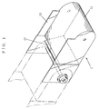
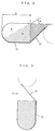
- Figs. 1-6 are used to explain an actual embodiment of the bucket conveyor of this invention.
- the bucket (1) is composed of a body (11) which has a U-shape cross-section, and a front end surface (12) which is connected on a slant to one edge of the body (11).
- the front end surface (12) is not attached to the body (11) except on the edge shared with the body (11).
- the bucket (1) has an opening for loading and unloading, which is bordered with an edge of the front end surface (12) and an edge on the opposite side of the edge shared between the body (11) and the front end surface (12). Both side surfaces of the body (11) extend vertically from the opening and forward from the front end surface (12), and serve as aprons (13).
- the aprons (13) are linked on both sides to the rear end of the preceding bucket by a rotating shaft (15), the front end surface (12) of the following bucket is flexibly contacted with pressure to the round rear end of the preceding bucket on the tangent of the round rear end.
- the preceding bucket and following bucket can be connected into a gapless train.
- the body (11) has a hole on each side of the front and rear ends for inserting the rotating shaft (15).
- the bucket (1) rotates on the rotating shaft (15) when changing the direction of conveyance from horizontal to vertical and vice-versa.
- the body (11) When the bucket (1) is conveyed horizontally, the body (11) becomes the sideways U-shape seen in Fig. 2. It is presumed that rice is loaded into the bucket from above while the bucket has this attitude. Looking at the bucket (1) itself, the opening is not horizontal. However, because the rear end of the preceding bucket exists over most of the extended line from the front end surface (12), the rear end of the preceding bucket serves as a part of the front end of the following bucket. Accordingly, the opening is horizontal for all practical purposes. Even if rice is loaded up to the top level of opening, the space (A) determined by the angle of repose ⁇ of the rice itself and the depth X of the body (11) is dead space and is not filled with rice.
- a rice loading port (14) is provided above the horizontal conveyance forwarding route sufficiently close to the bucket (1). Rice is loaded continuously into the buckets from the loading port (14). It is not necessary to carefully control loading speed. A small quantity of rice lands on top of the body (11), however it does not fall onto the conveyor floor because the bottom edge of the loading port (14) is lower than the aprons (13).
- the bucket (1) rotates on the rotating shaft (15) according to the direction of conveyance. Accordingly, the rice on the top of the body (11) slides along the top surface during the vertical conveyance forwarding route and is guided into the following bucket by the aprons (13).
- the rice in the bucket (1) is unloaded into an unloading port (16) when the bucket comes in the vertical conveyance returning route which causes the rice to slide along the front end (12). Rice falls under its own weight both when loaded into the bucket (1) and when unloaded from the bucket (1), therefore the shock applied to the rice is minimal. For this reason, the rice is not damaged.
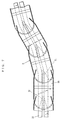
- the typical means of transmission has a sprocket (21) at the direction changing position in the conveyance route of the conveyor, as shown in Fig. 5.
- drive is obtained by engaging the rotating shaft (15) of the bucket (1) to the sprocket (21).
- the load applied to the rotating shaft (15) in the direction changing position of the bucket (1) is high, thus the sprocket (21) and the rotating shaft (15) are easily worn down.
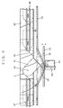
- this invented conveyor idealy uses a drive transmission mechanism shown in Fig. 6.
- a hook (17) is attached to the bottom of the bucket (1) and wheels (18) are attached to both ends of the rotating shaft (15).
- Guide rails (24) are located along the conveyance route on both sides of bucket (1).
- the bucket (1) is supported by the guide rails (24) via the wheels (18) while it is being conveyed.
- the drive transmission mechanism consists of a chain (22) which moves endlessly parallel to a part of the endless path of bucket (1), and sprockets (23 and 26) which engage the chain (22).
- the chain (22) is driven by a motor (25) via one of the sprockets (23) and, while moving, it pulls the bucket (1) when the hook (17) catches the chain (22) between front and rear sprockets (23 and 26).
- Multiple hooks (17), (three shown in figure) are attached to the chain (22), therefore drive power is distributed and excessive force is not applied to any part.
- this drive transmission mechanism is provided for both the horizontal conveyance route and the vertical conveyance route, excessive stress is not applied to the guide rails or the wheels when changing direction.
- the drive transmission mechanism is provided separately from the endless path of buckets, it can be easily added to the other preset mechanism.
- This embodiment differs from the bucket used in actual embodiment 1 in terms of bucket shape.
- the body (11) has a U-shape of vertical section, the bucket (1) can only turn in the vertical direction. With this conveyor, conveyance direction can be changed to the left and right as well.
- the rear end of the bucket (3) is basically spherical and is indented from the farthest protruding point towards the center of the sphere.
- the bottom of the indent (31) is linked to the front end surface (35) of the following bucket (3) by a ball-joint (32).
- the front end surface (35) is curved into a round shape when seen in the plane-sectional view, so as to complement each other with the rear end surface.
- the guide rails (33) are located below the bucket (3).
- the hooks (34) attached to the bottom of the bucket (3) project between the parallel guide rails (33). As with actual embodiment 1, by having the hooks (34) engage the drive transmission mechanism (2), the bucket (3) is driven in an endless motion.
- the unloading position is limited to a point in the returning route where the bucket is turned. Unlike actual embodiment 1, the unloading position of this conveyor can be set randomly.
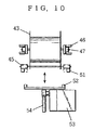
- the body (41) and the front end surface (42) can be separated.
- Aprons (43) are provided separately from side surface of the body (41).
- the front end surface (42) is fixed to the aprons (43).
- the body (41) is linked to the aprons (43) of the following bucket (4) by a rotating shaft (44).
- wheels (47) are attached, and the wheels are set on guide rails (46).
- the guide rails (46) guide the bucket (4) in the direction of conveyance.
- the bucket (4) has rollers (45) attached to the bottom, forward of the rotating shaft (44).
- the stationary rails (51) are straight in non-unloading positions so as keep the body (41) planar to the direction of conveyance. In the unloading position, the stationary rails (51) fall and rise to form a sinusoidal curve. Accordingly, the rollers (45) descend smoothly by using the aforementioned rotating shaft (44) as a fulcrum when leaving the linear path. The body (41) inclines whereby unloading the contents. After that, the rollers (45) rise again. The body (41) resumes a stable attitude and travels on the linear section of railing. In this way, the body (41) travels smoothly on the stationary rails (51) both while unloading its contents and when not. For this reason, it is not necessary to lower conveyance speed even when unloading the contents.
- mobile rails (52) are provided in the unloading position.
- the mobile rails (52) are driven by a motor (53) and can be raised and lowered in the vertical direction via a rack gear (54).
- the mobile rails (52) substitute for the stationary rails (51) in the unloading position, acting as an extension (55) of the linear section of the stationary rails (51). They are positioned next to the extension (55), thus keeping the body (41) planar to the direction of conveyance.
- the mobile rails (52) are lowered away from the position next to the extension (55). Accordingly, it is possible to freely set whether to unload in the unloading position or not.
- the rack gear (54) for raising and lowering the mobile rails (52) can be replaced with a ballscrew or cylinder.
- This embodiment differs from the buckets used in actual embodiments 1 through 3 in terms of bucket shape and coupling means.
- the rear end surface of the bucket is either curved like a U or a hemisphere and, by press-contacting the front end surface of the following bucket with the rear end surface of the preceding bucket, a gapless connection is made. Accordingly, when the direction of conveyance changes, the front end surface of the following bucket slides on the rear end surface of the preceding bucket, thus causing friction.
- the bucket conveyor of this actual embodiment couples preceding and following buckets with hinges, therefore sliding surface area is minimized and it is possible to minimize frictional resistance.
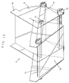
- the bucket (6) is shaped like an unequal-legged trapezoid when viewed as a vertical section planar to the direction of conveyance. And its internal volume is the same as with that of actual embodiment 1, which is based on the relation (A + B) ⁇ (A + C) .
- the front end surface (62) is either welded to the body (61) on the three edges other than the opening edge or is incorporated into a single body with the body (61) from the very beginning. Both sides of the body (61) extend vertically from the opening and serve as aprons (63). This point is the same as on actual embodiment 1.
- the bucket (6) has hinge pin holes (64 and 65 respectively) on the rear top edge of the body (61) and the top edge of the front end surface (62). Hinge pin holes (65) are provided on both ends in the shaft direction.
- the hinge pin hole (64) is concentrically designed so as to be pinched by hinge pin holes (65).
- the hinge pin holes (64 and 65) complement each other so that their total length in the shaft direction becomes equal to the width of the bucket (6).
- the hinge pin hole (64) on the preceding bucket and the hinge pin holes (65) on the following bucket form concentric circles and it is possible to securely link the preceding bucket to the following bucket by passing a hinge pin (66) through the holes.
- the hinge pin (66) serves as the rotating shaft of the bucket (6). Because the bucket (6) is linked by the hinge on the top edge of the front and rear ends, the amount of forward projection of the aprons (63) is slightly less than that in actual embodiment 1.
- a rice loading port (14) is provided above the horizontal conveyance forwarding route sufficiently close to the bucket (6). Rice is loaded continuously into the buckets from the loading port (14). It is not necessary to carefully control loading speed. A small quantity of rice lands on top of the body (61), however it does not fall onto the conveyor floor because the bottom edge of the loading port (14) is lower than the aprons (63).
- the bucket (6) rotates on a hinge pin (66) to negotiate the direction of conveyance. Accordingly, the rice on the top of the body (61) slides along the top surface and into the following bucket during the vertical conveyance forwarding route.
- the rice in the bucket (6) is unloaded into an unloading port (16) when the bucket comes in the vertical conveyance returning route which causes the rice to slide along front end surface (62).
- rice falls under its own weight both when loaded into the bucket (6) and when unloaded from the bucket (6), therefore the shock applied to the rice is minimal. For this reason, the rice is not damaged.
- this is an example of a system where unloading positions can be adjusted at will.
- this model excels over Embodiment 3 in that it does not require a stationary rail.
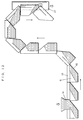
- the bucket (7) is composed of a main body (71) which has a round rear end, and an introduction (79).
- the introduction (79) has a sloped front end surface (72) and an opening.
- the body (71) and the introduction (79) are hinged via rotating shaft (74).
- a wheel shaft (73) is also positioned on the upper edge of front end surface (72) so that it is perpendicular to the direction of conveyance and parallel to the level of bucket opening.
- rollers (75) are also positioned on the upper edge of the body (71) which extends toward the back.
- the flange (78) is supported by the wheel shaft (73) of the following bucket (7) when the body (71) is in its regular position.
- the guide rail not in the diagram, as in Figs. 6 and 9, is situated on both sides of the bucket (7) and supports it, guiding it through to the direction of its conveyance.
- the ends of the wheel shaft (73) jutting out on both sides of the bucket (7) are coupled with the wheel shaft on the following bucket via the bar (70) in order to connect all buckets into a gapless train.
- the rotating shaft (75) penetrates the bar (70). Therefore, the introduction (79) is fixed onto the bar (70).
- a swing rail (76) is positioned pivotally on the horizontal conveyance route so it can be moved vertically.
- the swing rail (76) is supported horizontally by a cylinder (77) to form a sinusoidal curve supporting and guiding the bucket base at the unloading position so that the bucket can rotate and dump its contents.
- the rollers (75) move upward on the rail (76) while the wheel shaft (73) travels horizontally. Because of this, the rollers (75) receive opposing force and are delayed behind the wheel shaft (73), with the result that the body (71) rotates around the rotating shaft (74) and unloads contents. After this, the rollers (75) descend curve over the swing rail (76) so that the body (71) then resumes regular angle.
- the swing rail (76) When not unloading, the swing rail (76) is lowered by depressurizing the cylinder (77) and removed from contact with the body bottom, so that the bucket is conveyed suspended from the guide rails via the wheel shaft (73). Since the introduction (79) is fixed onto the bar (70), it will not rotate. Neither will the body (71) rotate by the weight of its load since it is also supported by the guide rails via the rotating shaft (74) and the wheel shaft (73) of the following bucket (7).
- the flange (78) acts also as a guide to slide loose grain spilt onto the top surface of the body (71) into the following bucket (7). That is, when the bucket (7) is shifting from planar to perpendicular positions, loose grain lodged onto the top surface of the body (71) slides over the flange (78) down to the introduction (79) of the following bucket (7).
- swing rail (76) drive force can be supplied either by cylinder or motor in combination with pinion racks, and other known methods.
- a dead space when grain is loaded from above up to or beyond the level of the bucket opening, a dead space results, constituting part of the interior at the rear.
- the space not filled with loose grains must have a volume being larger than the filled volume immediately below the opening.
- the volume of this dead space is determined by the grain's angle of repose and the bucket angle.
- angle of repose is characteristic to each grain type and cannot be changed.
- the capacity of this dead space may not fulfill the aforesaid requisite of (A + B) ⁇ (B + C) .
- the amount of grain fed into each bucket (B + C) is adjusted here by controlling the angles of feeding port and bucket.
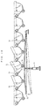
- the bucket 6 is identical to that in Actual embodiment 4. However, this example includes hopper (82) and guide rail (83).
- the hopper (82) is situated to be swung in pendulum fashion on the support shaft (84) stationed above the bucket conveyance track.
- On one side of the hopper (82) one end of the bolt (85) is pivotally attached.
- the other end of the bolt (85) penetrates hole (87) on a stationary structure (86) such as a wall or frame.
- the hopper (82) can be fixed at a stationary angle with nuts (88) and (89).
- the guide rails (83) are on both sides of the bucket (6) and are supporting the wheel shaft(66).
- the guide rails (83) are straight apart from corners, but is elliptical in the proximity of hopper (82). The radius is smallest directly below the support shaft (84).
- the bucket (6) resumes planar position directly below the support shaft (84),
- the hopper (82) is tilted toward lower right side as shown in solid line, and grain fed onto bucket in downward tilted position.
- the hopper (82) is tilted to lower left, so as to feed grain onto bucket in upward tilted position. In this way, the size of dead space may be adjusted by changing the grain feeder angle.
Landscapes
- Engineering & Computer Science (AREA)
- Mechanical Engineering (AREA)
- Chain Conveyers (AREA)
- Filling Or Emptying Of Bunkers, Hoppers, And Tanks (AREA)
Applications Claiming Priority (6)
| Application Number | Priority Date | Filing Date | Title |
|---|---|---|---|
| JP140837/97 | 1997-05-14 | ||
| JP14083797 | 1997-05-14 | ||
| JP221047/97 | 1997-08-01 | ||
| JP22104797 | 1997-08-01 | ||
| JP58986/98 | 1998-02-23 | ||
| JP05898698A JP3400940B2 (ja) | 1997-05-14 | 1998-02-23 | バケットコンベア |
Publications (1)
| Publication Number | Publication Date |
|---|---|
| EP0878422A1 true EP0878422A1 (de) | 1998-11-18 |
Family
ID=27296746
Family Applications (1)
| Application Number | Title | Priority Date | Filing Date |
|---|---|---|---|
| EP98107214A Withdrawn EP0878422A1 (de) | 1997-05-14 | 1998-04-21 | Becherförderer |
Country Status (8)
| Country | Link |
|---|---|
| US (1) | US6237745B1 (de) |
| EP (1) | EP0878422A1 (de) |
| JP (1) | JP3400940B2 (de) |
| KR (1) | KR100563377B1 (de) |
| CN (1) | CN1091062C (de) |
| AU (1) | AU734351B2 (de) |
| CA (1) | CA2236882A1 (de) |
| TW (1) | TW450925B (de) |
Cited By (2)
| Publication number | Priority date | Publication date | Assignee | Title |
|---|---|---|---|---|
| KR100563377B1 (ko) * | 1997-05-14 | 2006-07-25 | 교토지도기키 가부시키가이샤 | 버킷컨베이어 |
| WO2009079800A1 (de) * | 2007-12-20 | 2009-07-02 | Bühler AG | Becherförderer |
Families Citing this family (13)
| Publication number | Priority date | Publication date | Assignee | Title |
|---|---|---|---|---|
| JP4923734B2 (ja) | 2005-05-31 | 2012-04-25 | 株式会社湯山製作所 | 薬剤分包装置 |
| USD601174S1 (en) * | 2008-08-01 | 2009-09-29 | Oxbo International Corporation | Harvester bucket |
| US8205742B2 (en) * | 2008-08-01 | 2012-06-26 | Oxbo International Corporation | Harvester bucket |
| AU2016224240B2 (en) | 2015-02-26 | 2019-09-19 | Coledy Inc. | Passing device, valve, containing apparatus having same, contents moving apparatus and contents apparatus |
| KR20170091524A (ko) | 2016-02-01 | 2017-08-09 | 박서준 | 통과 장치, 밸브, 이를 구비하는 수용 기구, 내용물 이동 기구 및 내용물 기구 |
| CN109500369B (zh) * | 2017-09-15 | 2024-05-31 | 广西科技大学 | 一种升降回转式送坯装置 |
| CN108516287B (zh) * | 2018-04-13 | 2023-09-05 | 杭州和泰机电股份有限公司 | 一种新型翻斗式提升机 |
| CN108541547A (zh) * | 2018-04-18 | 2018-09-18 | 中山市立恒信息咨询有限公司 | 一种智能种植设备 |
| CN112456020A (zh) * | 2019-08-22 | 2021-03-09 | 福建省龙岩市博辉建筑劳务有限公司 | 一种石油开采用废土转运装置 |
| CN113650109B (zh) * | 2021-08-04 | 2022-09-27 | 常州贝高智能装备股份有限公司 | 同步进料定位矫正装置 |
| CN114669484B (zh) * | 2022-03-15 | 2023-04-14 | 江苏恒安供应链管理有限公司 | 一种用于物流运输的自动分拣设备 |
| CN116351739B (zh) * | 2022-12-28 | 2026-07-21 | 沈阳富创精密设备股份有限公司 | 一种自动分拣卸料机构 |
| CN116176934B (zh) * | 2023-04-26 | 2023-07-14 | 浏阳市金生红鹰烟花制造有限公司 | 一种圆型礼花弹的生产打包机构及其打包方法 |
Citations (5)
| Publication number | Priority date | Publication date | Assignee | Title |
|---|---|---|---|---|
| BE658685A (de) * | ||||
| GB720533A (en) * | 1950-11-11 | 1954-12-22 | Oates Kay | Improvements relating to conveyors |
| FR1507991A (fr) * | 1967-01-17 | 1967-12-29 | Hesser Ag Maschf | Convoyeur à chaîne pour matières en vrac |
| DE4223634A1 (de) * | 1992-07-17 | 1994-01-20 | Scholtz Conrad Gmbh | Taschenförderer |
| JPH0672519A (ja) * | 1992-08-25 | 1994-03-15 | Haaman:Kk | バケットコンベア |
Family Cites Families (20)
| Publication number | Priority date | Publication date | Assignee | Title |
|---|---|---|---|---|
| US146315A (en) * | 1874-01-13 | Improvement in buckets for windlass water-elevators | ||
| DE580957C (de) * | 1933-07-19 | A T G Allg Transportanlagen Ge | Mehrteiliger Traeger fuer Bandfoerderer und Kratzerfoerderer | |
| US565334A (en) * | 1896-08-04 | S pgtehs co | ||
| US437506A (en) * | 1890-09-30 | Endless conveyer | ||
| US645171A (en) * | 1899-12-15 | 1900-03-13 | Theodore C Simpson | Bucket-chain pump. |
| US667192A (en) * | 1900-02-10 | 1901-02-05 | William Robert Craig | Ore-conveyer. |
| US799489A (en) * | 1905-01-13 | 1905-09-12 | David J O'donnell | Bucket or tank for water-elevators. |
| US998678A (en) * | 1909-11-26 | 1911-07-25 | Dennis J Dowling | Pump-bucket. |
| US3112822A (en) * | 1960-12-02 | 1963-12-03 | May Fran Mfg Co | Bucket type conveyor mechanism |
| US3480131A (en) * | 1967-11-28 | 1969-11-25 | Chisholm Ryder Co Inc | Bucket conveyer |
| US3842967A (en) * | 1973-04-30 | 1974-10-22 | R Davis | Rotatable distributor-feeders to traveling receptacles |
| JPS58212505A (ja) * | 1982-05-31 | 1983-12-10 | V I V Eng Kk | バケツトエレベ−タ |
| JPS6072519A (ja) * | 1983-09-27 | 1985-04-24 | タイガー魔法瓶株式会社 | 液体加熱容器 |
| JPS6436312A (en) | 1987-07-31 | 1989-02-07 | Nec Corp | Miniaturized portable personal computer with light |
| JPH03122014A (ja) * | 1989-10-03 | 1991-05-24 | Sumitomo Chem Co Ltd | 充填材用粗大水酸化アルミニウムおよびその製造方法 |
| JPH04127713A (ja) * | 1990-09-19 | 1992-04-28 | Fujitsu Ltd | 半導体集積回路 |
| DE4244760C2 (de) * | 1992-07-17 | 1994-11-03 | Scholtz Conrad Gmbh | Taschenförderer |
| JP3400940B2 (ja) * | 1997-05-14 | 2003-04-28 | 京都自動機器株式会社 | バケットコンベア |
| US6334527B1 (en) * | 1997-05-14 | 2002-01-01 | Kyoji Co., Ltd. | Bucket conveyor |
| JP3122014U (ja) | 2006-03-15 | 2006-06-01 | 株式会社東京アールアンドデー | 車載用汎用スピーカーの取り付け構造 |
-
1998
- 1998-02-23 JP JP05898698A patent/JP3400940B2/ja not_active Expired - Fee Related
- 1998-04-16 TW TW087105798A patent/TW450925B/zh not_active IP Right Cessation
- 1998-04-21 EP EP98107214A patent/EP0878422A1/de not_active Withdrawn
- 1998-04-30 KR KR1019980015471A patent/KR100563377B1/ko not_active Expired - Fee Related
- 1998-05-04 CA CA002236882A patent/CA2236882A1/en not_active Abandoned
- 1998-05-12 US US09/075,865 patent/US6237745B1/en not_active Expired - Fee Related
- 1998-05-13 AU AU65974/98A patent/AU734351B2/en not_active Ceased
- 1998-05-13 CN CN98108362A patent/CN1091062C/zh not_active Expired - Fee Related
Patent Citations (5)
| Publication number | Priority date | Publication date | Assignee | Title |
|---|---|---|---|---|
| BE658685A (de) * | ||||
| GB720533A (en) * | 1950-11-11 | 1954-12-22 | Oates Kay | Improvements relating to conveyors |
| FR1507991A (fr) * | 1967-01-17 | 1967-12-29 | Hesser Ag Maschf | Convoyeur à chaîne pour matières en vrac |
| DE4223634A1 (de) * | 1992-07-17 | 1994-01-20 | Scholtz Conrad Gmbh | Taschenförderer |
| JPH0672519A (ja) * | 1992-08-25 | 1994-03-15 | Haaman:Kk | バケットコンベア |
Non-Patent Citations (1)
| Title |
|---|
| PATENT ABSTRACTS OF JAPAN vol. 018, no. 319 (M - 1623) 17 June 1994 (1994-06-17) * |
Cited By (2)
| Publication number | Priority date | Publication date | Assignee | Title |
|---|---|---|---|---|
| KR100563377B1 (ko) * | 1997-05-14 | 2006-07-25 | 교토지도기키 가부시키가이샤 | 버킷컨베이어 |
| WO2009079800A1 (de) * | 2007-12-20 | 2009-07-02 | Bühler AG | Becherförderer |
Also Published As
| Publication number | Publication date |
|---|---|
| KR100563377B1 (ko) | 2006-07-25 |
| KR19980086679A (ko) | 1998-12-05 |
| CN1091062C (zh) | 2002-09-18 |
| CA2236882A1 (en) | 1998-11-14 |
| JP3400940B2 (ja) | 2003-04-28 |
| AU734351B2 (en) | 2001-06-14 |
| JPH11100113A (ja) | 1999-04-13 |
| TW450925B (en) | 2001-08-21 |
| AU6597498A (en) | 1998-11-19 |
| CN1198875A (zh) | 1998-11-18 |
| US6237745B1 (en) | 2001-05-29 |
Similar Documents
| Publication | Publication Date | Title |
|---|---|---|
| US6334527B1 (en) | Bucket conveyor | |
| US6237745B1 (en) | Bucket conveyor | |
| US5526921A (en) | Intersecting bi-directional buckets for a bucket elevator system | |
| US4669674A (en) | Feeder box for a mobile transfer station | |
| US4446670A (en) | System to uniformly fill cases with fruit and vegetables | |
| US3031066A (en) | Swinging tray conveyors | |
| NL8401329A (nl) | Bandtransporteur voor het verticaal of steil transporteren van stortgoed. | |
| US5526922A (en) | High lift bucket | |
| US20040026215A1 (en) | Conveyor apparatus | |
| JP2912192B2 (ja) | ベルト式アンローダ | |
| CZ31592A3 (en) | set for catching and transportation of ballast, waste or another loose material | |
| CN218173527U (zh) | 一种用于托盘输送的链板输送机 | |
| KR20090062687A (ko) | 벌크 화물 하역 장치 | |
| US4694948A (en) | Travelling hopper belt car | |
| US6113335A (en) | Unloader | |
| CN110422582A (zh) | 输送臂和悬臂式隧道掘进机 | |
| WO1992001616A1 (en) | Conveyor | |
| JP2003012131A (ja) | 中間払い出し部を備えたベルトコンベヤ | |
| SU1150184A1 (ru) | Крутонаклонный конвейер | |
| US4848535A (en) | Ash conveyer | |
| US751890A (en) | Conveyer-loading device | |
| US1269588A (en) | Conveyer. | |
| JP2853363B2 (ja) | アンローダの荷役方法 | |
| CN119819587A (zh) | 一种物流输送线及其工作方法 | |
| GB2122158A (en) | Twin-belt elevator |
Legal Events
| Date | Code | Title | Description |
|---|---|---|---|
| PUAI | Public reference made under article 153(3) epc to a published international application that has entered the european phase |
Free format text: ORIGINAL CODE: 0009012 |
|
| AK | Designated contracting states |
Kind code of ref document: A1 Designated state(s): AT BE CH DE DK FR GB IT LI NL SE |
|
| AX | Request for extension of the european patent |
Free format text: AL;LT;LV;MK;RO;SI |
|
| 17P | Request for examination filed |
Effective date: 19981204 |
|
| AKX | Designation fees paid |
Free format text: AT BE CH DE DK FR GB IT LI NL SE |
|
| 17Q | First examination report despatched |
Effective date: 19991019 |
|
| STAA | Information on the status of an ep patent application or granted ep patent |
Free format text: STATUS: THE APPLICATION IS DEEMED TO BE WITHDRAWN |
|
| 18D | Application deemed to be withdrawn |
Effective date: 20041102 |