EP0875877B1 - Système de navigation - Google Patents
Système de navigation Download PDFInfo
- Publication number
- EP0875877B1 EP0875877B1 EP19980107642 EP98107642A EP0875877B1 EP 0875877 B1 EP0875877 B1 EP 0875877B1 EP 19980107642 EP19980107642 EP 19980107642 EP 98107642 A EP98107642 A EP 98107642A EP 0875877 B1 EP0875877 B1 EP 0875877B1
- Authority
- EP
- European Patent Office
- Prior art keywords
- current position
- road
- map matching
- presumed
- existing
- Prior art date
- Legal status (The legal status is an assumption and is not a legal conclusion. Google has not performed a legal analysis and makes no representation as to the accuracy of the status listed.)
- Expired - Lifetime
Links
- 238000000034 method Methods 0.000 claims description 51
- 238000012545 processing Methods 0.000 claims description 24
- 238000012937 correction Methods 0.000 claims description 2
- 238000010586 diagram Methods 0.000 description 8
- 230000015654 memory Effects 0.000 description 4
- 238000001514 detection method Methods 0.000 description 2
- 230000004044 response Effects 0.000 description 2
- 238000013459 approach Methods 0.000 description 1
- 238000006243 chemical reaction Methods 0.000 description 1
- 239000000284 extract Substances 0.000 description 1
- 230000010365 information processing Effects 0.000 description 1
- 238000005259 measurement Methods 0.000 description 1
Images


Classifications
-
- G—PHYSICS
- G01—MEASURING; TESTING
- G01C—MEASURING DISTANCES, LEVELS OR BEARINGS; SURVEYING; NAVIGATION; GYROSCOPIC INSTRUMENTS; PHOTOGRAMMETRY OR VIDEOGRAMMETRY
- G01C21/00—Navigation; Navigational instruments not provided for in groups G01C1/00 - G01C19/00
- G01C21/26—Navigation; Navigational instruments not provided for in groups G01C1/00 - G01C19/00 specially adapted for navigation in a road network
- G01C21/28—Navigation; Navigational instruments not provided for in groups G01C1/00 - G01C19/00 specially adapted for navigation in a road network with correlation of data from several navigational instruments
- G01C21/30—Map- or contour-matching
Definitions
- the present invention relates to a navigation system for detecting a current position of a moving vehicle.
- the navigation system is designed to perform "map matching" in order to correct this deviation.
- a presumed current position of the vehicle is detected by the dead-reckoning navigation at first. Then, all of roads in a predetermined distance range from the presumed current position are retrieved from the map data, and a position on a road having the highest existence probability of the vehicle, for example, a road existing at the position closest to the presumed current position among the retrieved roads is derived as an ultimate current position of the vehicle.
- an object of the invention to provide a navigation system which can accurately detect a current position of a moving vehicle at a high speed and allow the current position to be displayed on a map while executing a position correction by a map matching process.
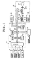
- Fig. 1 is a diagram showing a navigation system according to the invention.
- an azimuth sensor 1 detects a running azimuth of a vehicle as a moving vehicle
- an angular velocity sensor 2 detects an angular velocity of the vehicle
- a distance sensor 3 detects a running distance of the vehicle.
- a GPS (Global Positioning System) 4 detects the absolute position of the vehicle from latitude and longitude information or the like obtained by using radio waves transmitted from a position measuring artificial satellite. Detection outputs of the sensors (apparatuses) are supplied to a system controller 5.
- the azimuth sensor 1 for example, a geomagnetism sensor for detecting the running azimuth of the vehicle by geomagnetism (earth magnetic field) is used.
- the distance sensor 3 is constituted by a pulse generator for generating a pulse every rotation of a predetermined angle of a drive shaft (not shown) of the vehicle.
- the pulse generator is a known generator for magnetically or optically detecting a rotational angle position of the drive shaft and generating pulses.
- the system controller 5 is a so called computer which comprises: an interface 6 for receiving detection outputs of the sensors (apparatuses) 1 to 4 and executing a process such as A/D (analog/digital) conversion or the like; a CPU (central processing unit) 7 for performing various image data processes and executing arithmetic operations of the running distance, running azimuth, coordinates (longitude, latitude) of the current position, and the like, of the vehicle based on the output data of the sensors (apparatuses) 1 to 4 which is sequentially transmitted from the interface 6; an ROM (read only memory) 8 in which various processing programs of the CPU 7 and other necessary information have been preliminarily written; and RAMs (random access memories) 9 and 22 to and from which information necessary to execute the programs are written and read out.
- a process such as A/D (analog/digital) conversion or the like
- a CPU (central processing unit) 7 for performing various image data processes and executing arithmetic operations of the running distance, running azi
- an external storage device 11 in addition to map data in which points on roads in a map are converted into digital values (numerical values), longitude and latitude data showing a range of each road unit as road information, which will be described below, connecting relation data among the road units, and location display pattern data have been preliminarily stored. Further, in the external storage device 11, various programs for executing the operation of the invention, which will be described below, have been preliminarily stored. Actually, the various data and programs have been preliminarily recorded in a CD-ROM, a DVD-ROM, or the like as a recording medium set in the external storage device 11. As a recording medium, a DAT, an IC card, or the like can be also used. The writing and reading operations of the external storage device 11 are controlled by the CPU 7. In this case, the various data and programs read out from the external storage device 11 are fetched into the system controller 5 via a bus line 23.
- a display apparatus 16 comprises: a display 17 such as a CRT or the like; a graphic memory 18 such as a V (Video)-RAM or the like; a graphic controller 19 for drawing map data sent from the system controller 5 as image data into the graphic memory 18 and outputting the image data; and a display controller 20 for controlling so as to display a map on the display 17 on the basis of the image data outputted from the graphic controller 19.
- An input device 21 is constituted by a keyboard or the like and various commands and the like are generated to the system controller 5 by a key operation of the user.
- the CPU 7 executes a program supplied via the bus line 23 as mentioned above.
- the CPU 7 exits from the operation of a main flow (which is not explained) which is being executed currently in response to the start of the movement of a vehicle and advances to the execution of the initial current position detecting routine as shown in Fig. 2.
- the CPU 7 calculates the presumed current position of the vehicle based on the output data from each of the azimuth sensor 1, angular velocity sensor 2, distance sensor 3, and GPS 4 by using the dead-reckoning navigation.
- the CPU 7 stores the calculated presumed current position into the built-in register A in the CPU 7 as shown in Fig. 3 (step S1).
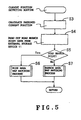
- the CPU 7 proceeds to a wide area map matching processing routine (step S2).
- the CPU 7 reads out map data of an ambient area including the presumed current position from the external storage device 11. Subsequently, the CPU 7 selects all of roads existing in a predetermined area (for example, in a range within the radius of 300 meters) around the presumed current position as a center from road data existing in map data of the ambient area. The CPU 7 then retrieves a road existing at a position that is the closest to the presumed current position from among the selected roads and determines that the retrieved road is the road on which the vehicle is running. In this case, the CPU 7 stores current running road information indicative of the road which has been determined to be the road on which the vehicle is running currently into the built-in register C in the CPU 7 as shown in Fig. 3.
- the CPU 7 uses the position that is the closest to the presumed current position on the road shown by the current running road information as a final current position of the vehicle and stores the current position information indicative of the current position into the built-in register B in the CPU 7 as shown in Fig. 3. Subsequently, the CPU 7 causes the display, on the display 17, of the position where the current position mark has been added to the position shown by the current position information on the map data of the ambient area.
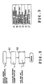
- the presumed current position of the vehicle is shown by (X) and the map data of the ambient area including the presumed current position (X) is shown by (R).
- the CPU 7 selects all of roads existing in map data (R), that is, roads existing in a predetermined area around the presumed current position (X) as a center, that is, roads existing in a broken line circle in Fig. 4. That is, the roads d 2 to d 4 are selected from the roads d 1 to d 4 .
- the CPU 7 retrieves the road d 2 existing at a position that is the closest to the presumed current position (X) from the selected roads.
- the CPU 7 displays the map data (R) as shown in Fig. 4 in which a current position mark (M) indicative of the current position of the vehicle is added to the position that is the closest to the presumed current position (X) on the retrieved road d 2 onto the display 17.
- the CPU 7 exits from the initial current position detecting routine and advances to the current position detecting routine as shown in Fig. 5.
- the CPU 7 calculates the newest presumed current position of the vehicle which is running currently on the basis of the output data from each of the azimuth sensor 1, angular velocity sensor 2, distance sensor 3, and GPS 4.
- the CPU 7 overwrites and stores the calculated presumed current position into the built-in register A in the CPU 7 as shown in Fig. 3 (step S3).
- the CPU 7 reads out road branch point data indicative of all of road branch points existing in the ambient area of the current position shown by the current position information stored in the built-in register B in the CPU 7 as shown in Fig. 3 from the external storage device 11 (step S4).
- the CPU 7 determines whether the current position of the vehicle has approached a position near any one of a plurality of road branch points shown by the road branch point data or not (for example, within a range of 100 meters from the road branch point) (step S5). For example, when a distance from the presumed current position to the next road branch point becomes smaller than a predetermined distance (for instance, 100 meters), it is determined that the vehicle has approached the road branch point.
- a predetermined distance for instance, 100 meters
- step S5 When it is determined in step S5 that the current position of the vehicle has approached the road branch point, the CPU 7 advances to the wide area map matching processing routine (step S6).
- the CPU 7 first reads out the map data of the ambient area including the presumed current position indicated by the presumed current position information stored in the built-in register A as shown in Fig. 3 from the external storage device 11.
- the CPU 7 selects all of roads existing in a predetermined area (for example, within a range of the radius of 300 meters) around the presumed current position as a center among road data existing in the map data of the ambient area.
- the CPU 7 retrieves a road which exists at a position that is the closest to the presumed current position and in which it is considered that the existence probability of the vehicle is the highest from the selected roads and determines that the retrieved road is the road on which the vehicle is running currently.
- the CPU 7 stores current running road information indicative of the road which is determined as a road on which the vehicle is running currently into the built-in register C in the CPU 7 as shown in Fig. 3.
- the CPU 7 sets the position that is the closest to the presumed current position on the road shown by the current running road information to a final current position of the vehicle and stores the information indicative of the current position into the built-in register B in the CPU 7 as shown in Fig. 3.
- the CPU 7 allows the position in which the current position mark is added to the position shown by the current position information on the map data of the ambient area to be displayed on the display 17.
- the wide area map matching processing routine which is executed by step S6 is the same process as the wide area map matching processing routine executed in step S2 in Fig. 2 as described above.
- step S5 if it is determined that the vehicle is away from any one of the road branch points, the CPU 7 advances to the execution of a narrow area map matching processing routine (step S7).
- the wide area map matching process as mentioned above is executed.
- the narrow area map matching process is executed.
- the CPU 7 first reads out map data of a ambient area including the above presumed current position (position shown by the information stored in the built-in register A) from the external storage device 11. The CPU 7 subsequently selects all of the roads existing in a micro area (for example, range within a radius of 10 m) around the presumed current position as a center from the road data existing in the map data of the ambient area. The CPU 7 subsequently searches the road which exists at the nearest position of the presumed current position from the selected roads and determines that the searched road is the road where the vehicle is running currently. In this instance, the CPU 7 stores the current running road information showing the road decided as a road where the vehicle is running currently into the built-in register C of the CPU 7 as shown in Fig. 3.
- a micro area for example, range within a radius of 10 m
- the CPU 7 decides the position that is the closest to the presumed current position on the road shown by the current running road information as a final current position of the vehicle.
- the information indicative of the current position is stored into the built-in register B of the CPU 7 as shown in Fig. 3.
- the CPU 7 allows the position in which the current position mark is added to the position shown by the current position information on the map data of the ambient area to be displayed on the display 17.
- an area to be used as a target of the map matching is reduced as compared with that in the wide area map matching process as mentioned above.
- the map matching process in the wide area map matching process, is executed to the road existing in a predetermined area shown in a circle of a broken line.
- the map matching process is performed to the road existing in a micro area shown in a circle of an alternate long and short dash line.
- the number of roads which should become the targets of the map matching process (wide area: roads d 2 to d 4 , narrow area: road d 2 ) is smaller.
- a higher speed process is, therefore, performed as compared with the wide area map matching process.
- Fig. 6 is a diagram showing an example of a narrow area map matching processing routine performed in consideration of the above point.
- the CPU 7 first obtains an azimuth of the moving direction of the vehicle which is currently running on the basis of the output data from the azimuth sensor 1 and stores information showing the azimuth of movement into a built-in register D of the CPU 7 as shown in Fig. 3 (step S71).
- the CPU 7 subsequently obtains a movement distance of the vehicle from the position shown by the current position information stored in the built-in register B on the basis of the output data from the distance sensor 3.
- Information showing the movement distance is stored into a built-in register E of the CPU 7 as shown in Fig. 3 (step S72).
- the CPU 7 reads out road data of the road shown by the current running road information stored in the built-in register C from the external storage device 11, extracts road azimuth data showing the road azimuth at the current position shown by the current position information stored in the built-in register B from the road data, and stores into a built-in register F of the CPU 7 as shown in Fig. 3 (step S73).
- the CPU 7 obtains an angle difference ⁇ obtained by subtracting the road azimuth shown by the road azimuth data from the azimuth of movement indicated by the moving azimuth information (step S74).
- step S75 when it is determined that the absolute value of the angle difference ⁇ is larger than the predetermined angle difference ⁇ k , the CPU 7 advances the execution of an off road running processing routine (step S76).
- step S75 when the current azimuth of movement of the vehicle is largely deviated from the road azimuth on the map road at the current position of the vehicle, it is determined by step S75 that the vehicle is running on the road or district which is not registered as road data, thereby executing the off road running process.
- the CPU 7 reads out the map data of the ambient area including the presumed current position shown by the presumed current position information stored in the built-in register A as shown in Fig. 3 from the external storage device 11.
- the CPU 7 sets the presumed current position shown by the presumed current position information as a final current position of the vehicle and overwrites and stores the current position information showing the current position into the built-in register B of the CPU 7 as shown in Fig. 3.
- the CPU 7 allows the position on the map data of the ambient area where the current position mark is added to the position shown by the current position information to be displayed on the display 17.
- step S75 when it is determined that the absolute value of the angle difference e is smaller than the predetermined angle difference ⁇ k , the CPU 7 advances to the execution of a relative position calculation processing routine (step S77).
- the CPU 7 calculates a relative position in which the position shown by the current position information stored in the built-in register B is set to a reference position on the basis of each of the movement distance of the vehicle and the angle data on the map road at the current position stored in the built-in registers C and D in Fig. 3.
- the CPU 7 sets the calculated position to the final current position of the vehicle and overwrites and stores the information indicative of the current position into the built-in register B of the CPU 7.
- the CPU 7 allows the position in the map data of the ambient area where the current position mark is added to the position shown by the current position information to be displayed on the display 17.
- the final current position is obtained on the basis of the position on the road obtained previously, the movement distance from this position, and the road azimuth on the map data in the running road interval.
- the position obtained by the relative position calculating process therefore, is certainly pulled onto the map road.
- step S77 When either the relative position calculating process in step S77 shown in Fig. 6 or the off road running process in step S76 is finished, the CPU 7 skips the narrow area map matching processing routine as shown in Fig. 6 and is returned to the current position detecting routine shown in Fig. 5.
- the CPU 7 skips the current position detecting routine and returns to the operation of a main flow (not shown). In this instance, the current position detecting routine shown in Fig. 5 is repeatedly executed every predetermined period during the execution of the main flow.
- the wide area map matching process with respect to all of the roads displayed on the map as targets is executed.
- the narrow area map matching process in which the area to be processed as a target is narrowed is executed, thereby reducing the processing time.
- the high speed map matching process is accurately executed not only during the running on the road but also during the running in a woodland path away from the road or in a parking lot or the like.
Landscapes
- Engineering & Computer Science (AREA)
- Radar, Positioning & Navigation (AREA)
- Remote Sensing (AREA)
- Automation & Control Theory (AREA)
- Physics & Mathematics (AREA)
- General Physics & Mathematics (AREA)
- Navigation (AREA)
- Traffic Control Systems (AREA)
- Instructional Devices (AREA)
Claims (8)
- Système de navigation pour obtenir une position actuelle d'un véhicule en mouvement par l'intermédiaire d'une correction de correspondance à une carte d'une position actuelle présumée du véhicule en mouvement obtenue sur la base d'une navigation à l'estime, ledit système comprenant :des moyens de traitement de mise en correspondance avec une carte de zone étendue pour obtenir une première position en tant que dite position actuelle, ladite première position étant sur une route existant à une position qui est la plus proche de ladite position actuelle présumée parmi les routes existant dans une première zone contenant ladite position actuelle présumée ;des moyens de traitement de mise en correspondance avec une carte de zone réduite pour obtenir une deuxième position en tant que dite position actuelle, ladite deuxième position étant sur une route existant à une position qui est la plus proche de ladite position actuelle présumée parmi les routes existant dans une deuxième zone plus petite que ladite première zone ; etdes moyens de contrôle pour, alternativement, amener les uns ou les autres desdits moyens de traitement de mise en correspondance avec une carte de zone étendue et desdits moyens de traitement de mise en correspondance avec une carte de zone réduite à fonctionner sur la base de données de carte autour de ladite position actuelle présumée.
- Système selon la revendication 1, dans lequel lesdits moyens de contrôle amènent lesdits moyens de traitement de mise en correspondance avec une carte de zone étendue à fonctionner lorsque ledit véhicule en mouvement est présent à proximité d'un point d'embranchement de routes et amènent lesdits moyens de traitement de mise en correspondance avec une carte de zone réduite à fonctionner lorsque ledit véhicule en mouvement est présent à une position éloignée du point d'embranchement de routes.
- Système selon la revendication 1 ou 2, dans lequel lesdits moyens de traitement de mise en correspondance avec une carte de zone étendue déterminent une route existant à une position qui est la plus proche de ladite position actuelle présumée parmi les routes existant dans ladite première zone en tant que route de circulation actuelle et obtiennent ladite première position sur ladite route de circulation actuelle en tant que dite position actuelle.
- Système selon l'une quelconque des revendications 1 à 3, dans lequel lesdits moyens de traitement de mise en correspondance avec une carte de zone réduite déterminent une route existant à une position qui est la plus proche de ladite position actuelle présumée parmi les routes existant dans ladite deuxième zone en tant que route de circulation actuelle et obtiennent ladite deuxième position sur ladite route de circulation actuelle en tant que dite position actuelle.
- Système selon l'une quelconque des revendications 1 à 4, dans lequel lesdites première et deuxième zones sont centrées sur ladite position actuelle présumée.
- Système selon l'une quelconque des revendications 3 à 5, dans lequel lesdits moyens de traitement de mise en correspondance avec une carte de zone réduite obtiennent une nouvelle position actuelle dudit véhicule en mouvement sur la base d'un azimut de route sur ladite route de circulation actuelle à ladite position actuelle et d'une distance de déplacement dudit véhicule en mouvement par rapport à ladite position actuelle.
- Système selon la revendication 6, dans lequel lesdits moyens de traitement de mise en correspondance avec une carte de zone réduite comportent des moyens de traitement de circulation hors route pour déduire ladite position actuelle présumée en tant que position actuelle finale dudit véhicule en mouvement tel qu'il est lorsqu'une différence angulaire entre un azimut de déplacement dudit véhicule en mouvement et un azimut de route est supérieure à une différence angulaire prédéterminée.
- Support d'enregistrement pour un système de navigation comportant un ordinateur, dans lequel un programme est enregistré sur ledit support d'enregistrement, amenant ledit ordinateur à exécuter une opération comprenant :un processus d'obtention d'une position actuelle présumée d'un véhicule en mouvement sur la base d'une navigation à l'estime ;un processus de mise en correspondance avec une carte de zone étendue pour obtenir une première position en tant que dite position actuelle, ladite première position étant sur une route existant à une position qui est la plus proche de ladite position actuelle présumée parmi les routes existant dans une première zone contenant ladite position actuelle présumée ; etun processus de mise en correspondance avec une carte de zone réduite pour obtenir une deuxième position en tant que dite position actuelle, ladite deuxième position étant sur une route existant à une position qui est la plus proche de ladite position actuelle présumée parmi les routes existant dans une deuxième zone plus petite que ladite première zone ; etune étape de contrôle pour effectuer, alternativement, l'un ou l'autre dudit processus de mise en correspondance avec une carte de zone étendue et dudit processus de mise en correspondance avec une carte de zone réduite sur la base de données de carte autour de ladite position actuelle présumée.
Applications Claiming Priority (3)
| Application Number | Priority Date | Filing Date | Title |
|---|---|---|---|
| JP11481897 | 1997-05-02 | ||
| JP9114818A JPH10307037A (ja) | 1997-05-02 | 1997-05-02 | ナビゲーション装置 |
| JP114818/97 | 1997-05-02 |
Publications (3)
| Publication Number | Publication Date |
|---|---|
| EP0875877A2 EP0875877A2 (fr) | 1998-11-04 |
| EP0875877A3 EP0875877A3 (fr) | 2000-09-20 |
| EP0875877B1 true EP0875877B1 (fr) | 2004-06-30 |
Family
ID=14647462
Family Applications (1)
| Application Number | Title | Priority Date | Filing Date |
|---|---|---|---|
| EP19980107642 Expired - Lifetime EP0875877B1 (fr) | 1997-05-02 | 1998-04-27 | Système de navigation |
Country Status (3)
| Country | Link |
|---|---|
| EP (1) | EP0875877B1 (fr) |
| JP (1) | JPH10307037A (fr) |
| DE (1) | DE69824789T2 (fr) |
Cited By (1)
| Publication number | Priority date | Publication date | Assignee | Title |
|---|---|---|---|---|
| US8219314B2 (en) | 1999-07-28 | 2012-07-10 | Panasonic Corporation | Method for transmitting location information on a digital map, apparatus for implementing the method and traffic information provision/reception system |
Families Citing this family (15)
| Publication number | Priority date | Publication date | Assignee | Title |
|---|---|---|---|---|
| JP3481168B2 (ja) | 1999-08-27 | 2003-12-22 | 松下電器産業株式会社 | デジタル地図の位置情報伝達方法 |
| DE10021373A1 (de) * | 2000-05-02 | 2001-11-08 | Siemens Ag | Verfahren zur Positionsbestimmung und Navigationsgerät |
| SE0004096D0 (sv) | 2000-11-08 | 2000-11-08 | Nira Automotive Ab | Positioning system |
| JP5041638B2 (ja) | 2000-12-08 | 2012-10-03 | パナソニック株式会社 | デジタル地図の位置情報伝達方法とそれに使用する装置 |
| JP4663136B2 (ja) | 2001-01-29 | 2011-03-30 | パナソニック株式会社 | デジタル地図の位置情報伝達方法と装置 |
| JP4749594B2 (ja) | 2001-04-27 | 2011-08-17 | パナソニック株式会社 | デジタル地図の位置情報伝達方法 |
| JP4230132B2 (ja) | 2001-05-01 | 2009-02-25 | パナソニック株式会社 | デジタル地図の形状ベクトルの符号化方法と位置情報伝達方法とそれを実施する装置 |
| JP4402318B2 (ja) | 2001-05-08 | 2010-01-20 | パイオニア株式会社 | ナビゲーション装置 |
| JP2002333334A (ja) | 2001-05-08 | 2002-11-22 | Pioneer Electronic Corp | カーナビゲーション装置 |
| JP2006177862A (ja) | 2004-12-24 | 2006-07-06 | Aisin Aw Co Ltd | ナビゲーション装置 |
| JP4710740B2 (ja) * | 2006-07-04 | 2011-06-29 | 株式会社デンソー | 位置情報利用装置 |
| JP4735480B2 (ja) | 2006-09-01 | 2011-07-27 | 株式会社デンソー | 車両位置検出システム |
| JP4573899B2 (ja) * | 2006-12-21 | 2010-11-04 | パイオニア株式会社 | ナビゲーション装置、マップマッチング方法、及び、マップマッチングプログラム |
| DE102009027919B4 (de) | 2009-07-22 | 2019-02-28 | Robert Bosch Gmbh | Verfahren und Vorrichtung zum Navigieren eines Fahrzeuges |
| CN108168567A (zh) * | 2017-11-22 | 2018-06-15 | 东南大学 | 一种基于电子地图实现高精度定位服务的方法 |
Family Cites Families (9)
| Publication number | Priority date | Publication date | Assignee | Title |
|---|---|---|---|---|
| JPS61216098A (ja) * | 1985-03-20 | 1986-09-25 | 日産自動車株式会社 | 車両用経路誘導装置 |
| JP2646453B2 (ja) * | 1988-04-28 | 1997-08-27 | マツダ株式会社 | 車両用ナビゲーション装置 |
| JP3231070B2 (ja) * | 1992-02-28 | 2001-11-19 | クラリオン株式会社 | ナビゲーション装置における走行経路一致方法 |
| JPH0682261A (ja) * | 1992-09-02 | 1994-03-22 | Fujitsu Ten Ltd | 簡易型経路探索/誘導装置 |
| JPH06288780A (ja) * | 1993-04-02 | 1994-10-18 | Fujitsu Ten Ltd | 車両位置検出装置 |
| JPH06300579A (ja) * | 1993-04-13 | 1994-10-28 | Fujitsu Ten Ltd | 車両位置検出装置 |
| JPH0868656A (ja) * | 1994-08-31 | 1996-03-12 | Alpine Electron Inc | 車載用ナビゲーション装置 |
| JP3451162B2 (ja) * | 1996-05-09 | 2003-09-29 | アルパイン株式会社 | ナビゲーション装置及び移動体の現在位置修正方式 |
| JP2828034B2 (ja) * | 1996-05-29 | 1998-11-25 | ソニー株式会社 | ナビゲーション装置 |
-
1997
- 1997-05-02 JP JP9114818A patent/JPH10307037A/ja active Pending
-
1998
- 1998-04-27 EP EP19980107642 patent/EP0875877B1/fr not_active Expired - Lifetime
- 1998-04-27 DE DE69824789T patent/DE69824789T2/de not_active Expired - Fee Related
Cited By (1)
| Publication number | Priority date | Publication date | Assignee | Title |
|---|---|---|---|---|
| US8219314B2 (en) | 1999-07-28 | 2012-07-10 | Panasonic Corporation | Method for transmitting location information on a digital map, apparatus for implementing the method and traffic information provision/reception system |
Also Published As
| Publication number | Publication date |
|---|---|
| DE69824789T2 (de) | 2005-07-14 |
| EP0875877A3 (fr) | 2000-09-20 |
| EP0875877A2 (fr) | 1998-11-04 |
| DE69824789D1 (de) | 2004-08-05 |
| JPH10307037A (ja) | 1998-11-17 |
Similar Documents
| Publication | Publication Date | Title |
|---|---|---|
| EP0875877B1 (fr) | Système de navigation | |
| US4837700A (en) | Method and apparatus for processing data in a GPS receiving device in a road vehicle | |
| US5119301A (en) | Vehicle location detecting system | |
| US4964052A (en) | Navigation device for use in a vehicle | |
| CN1821719B (zh) | 导航系统中引导移动物体的行驶路线的方法以及导航系统 | |
| US5317515A (en) | Vehicle heading correction apparatus | |
| US4982332A (en) | Road data generating method for use in an on-board navigation system | |
| JP5142047B2 (ja) | ナビゲーション装置及びナビゲーション用プログラム | |
| EP2224209B1 (fr) | Dispositif de navigation et procédé de navigation | |
| US4897792A (en) | Method of memorizing travel locus data for use in an automotive navigation system | |
| EP0508787B1 (fr) | Appareil de navigation à bord | |
| US5442559A (en) | Navigation apparatus | |
| JP3442138B2 (ja) | ナビゲーション装置及び方法 | |
| JPH064023A (ja) | ナビゲーションシステム用軌跡表示装置 | |
| JPH05113342A (ja) | ナビゲーシヨン装置 | |
| JP2008032632A (ja) | 角速度センサのキャリブレーション装置および角速度値特定装置 | |
| JPH0781872B2 (ja) | 位置検出精度判定方法およびその方法を用いた車両誘導装置 | |
| JP3140130B2 (ja) | ナビゲーション装置 | |
| JP2577160B2 (ja) | 車両位置検出装置 | |
| EP0601712A1 (fr) | Système de navigation | |
| JP3210483B2 (ja) | 車両位置修正方式 | |
| JP3435257B2 (ja) | マップマッチング方法 | |
| JP3653121B2 (ja) | 車載用経路探索装置および推奨ルート表示方法 | |
| JPH0754351B2 (ja) | Gps受信装置のデ−タ処理方法 | |
| JP2007322312A (ja) | ナビゲーション装置 |
Legal Events
| Date | Code | Title | Description |
|---|---|---|---|
| PUAI | Public reference made under article 153(3) epc to a published international application that has entered the european phase |
Free format text: ORIGINAL CODE: 0009012 |
|
| AK | Designated contracting states |
Kind code of ref document: A2 Designated state(s): DE FR GB |
|
| AX | Request for extension of the european patent |
Free format text: AL;LT;LV;MK;RO;SI |
|
| PUAL | Search report despatched |
Free format text: ORIGINAL CODE: 0009013 |
|
| AK | Designated contracting states |
Kind code of ref document: A3 Designated state(s): AT BE CH CY DE DK ES FI FR GB GR IE IT LI LU MC NL PT SE |
|
| AX | Request for extension of the european patent |
Free format text: AL;LT;LV;MK;RO;SI |
|
| 17P | Request for examination filed |
Effective date: 20000927 |
|
| AKX | Designation fees paid |
Free format text: DE FR GB |
|
| 17Q | First examination report despatched |
Effective date: 20030320 |
|
| GRAP | Despatch of communication of intention to grant a patent |
Free format text: ORIGINAL CODE: EPIDOSNIGR1 |
|
| GRAS | Grant fee paid |
Free format text: ORIGINAL CODE: EPIDOSNIGR3 |
|
| GRAA | (expected) grant |
Free format text: ORIGINAL CODE: 0009210 |
|
| AK | Designated contracting states |
Kind code of ref document: B1 Designated state(s): DE FR GB |
|
| REG | Reference to a national code |
Ref country code: GB Ref legal event code: FG4D |
|
| REF | Corresponds to: |
Ref document number: 69824789 Country of ref document: DE Date of ref document: 20040805 Kind code of ref document: P |
|
| ET | Fr: translation filed | ||
| PLBE | No opposition filed within time limit |
Free format text: ORIGINAL CODE: 0009261 |
|
| STAA | Information on the status of an ep patent application or granted ep patent |
Free format text: STATUS: NO OPPOSITION FILED WITHIN TIME LIMIT |
|
| REG | Reference to a national code |
Ref country code: GB Ref legal event code: 746 Effective date: 20050504 |
|
| 26N | No opposition filed |
Effective date: 20050331 |
|
| REG | Reference to a national code |
Ref country code: FR Ref legal event code: D6 |
|
| PGFP | Annual fee paid to national office [announced via postgrant information from national office to epo] |
Ref country code: FR Payment date: 20060420 Year of fee payment: 9 |
|
| PGFP | Annual fee paid to national office [announced via postgrant information from national office to epo] |
Ref country code: GB Payment date: 20060426 Year of fee payment: 9 |
|
| PGFP | Annual fee paid to national office [announced via postgrant information from national office to epo] |
Ref country code: DE Payment date: 20060630 Year of fee payment: 9 |
|
| GBPC | Gb: european patent ceased through non-payment of renewal fee |
Effective date: 20070427 |
|
| PG25 | Lapsed in a contracting state [announced via postgrant information from national office to epo] |
Ref country code: DE Free format text: LAPSE BECAUSE OF NON-PAYMENT OF DUE FEES Effective date: 20071101 |
|
| PG25 | Lapsed in a contracting state [announced via postgrant information from national office to epo] |
Ref country code: GB Free format text: LAPSE BECAUSE OF NON-PAYMENT OF DUE FEES Effective date: 20070427 |
|
| PG25 | Lapsed in a contracting state [announced via postgrant information from national office to epo] |
Ref country code: FR Free format text: LAPSE BECAUSE OF NON-PAYMENT OF DUE FEES Effective date: 20070430 |