EP0874109B1 - Vorrichtung zur Abhebesicherung eines Laufbelags für ein Baugerüst - Google Patents
Vorrichtung zur Abhebesicherung eines Laufbelags für ein Baugerüst Download PDFInfo
- Publication number
- EP0874109B1 EP0874109B1 EP98104964A EP98104964A EP0874109B1 EP 0874109 B1 EP0874109 B1 EP 0874109B1 EP 98104964 A EP98104964 A EP 98104964A EP 98104964 A EP98104964 A EP 98104964A EP 0874109 B1 EP0874109 B1 EP 0874109B1
- Authority
- EP
- European Patent Office
- Prior art keywords
- crossbar
- securing
- support
- scaffolding
- holding means
- Prior art date
- Legal status (The legal status is an assumption and is not a legal conclusion. Google has not performed a legal analysis and makes no representation as to the accuracy of the status listed.)
- Expired - Lifetime
Links
- 238000006073 displacement reaction Methods 0.000 claims description 5
- 230000000284 resting effect Effects 0.000 claims 1
- 230000005484 gravity Effects 0.000 description 3
- 238000011161 development Methods 0.000 description 2
- 230000018109 developmental process Effects 0.000 description 2
- 238000003780 insertion Methods 0.000 description 2
- 230000037431 insertion Effects 0.000 description 2
- 230000015572 biosynthetic process Effects 0.000 description 1
- 210000000078 claw Anatomy 0.000 description 1
- 230000013011 mating Effects 0.000 description 1
Images

Classifications
-
- E—FIXED CONSTRUCTIONS
- E04—BUILDING
- E04G—SCAFFOLDING; FORMS; SHUTTERING; BUILDING IMPLEMENTS OR AIDS, OR THEIR USE; HANDLING BUILDING MATERIALS ON THE SITE; REPAIRING, BREAKING-UP OR OTHER WORK ON EXISTING BUILDINGS
- E04G7/00—Connections between parts of the scaffold
- E04G7/02—Connections between parts of the scaffold with separate coupling elements
- E04G7/28—Clips or connections for securing boards
-
- E—FIXED CONSTRUCTIONS
- E04—BUILDING
- E04G—SCAFFOLDING; FORMS; SHUTTERING; BUILDING IMPLEMENTS OR AIDS, OR THEIR USE; HANDLING BUILDING MATERIALS ON THE SITE; REPAIRING, BREAKING-UP OR OTHER WORK ON EXISTING BUILDINGS
- E04G1/00—Scaffolds primarily resting on the ground
- E04G1/15—Scaffolds primarily resting on the ground essentially comprising special means for supporting or forming platforms; Platforms
-
- E—FIXED CONSTRUCTIONS
- E04—BUILDING
- E04G—SCAFFOLDING; FORMS; SHUTTERING; BUILDING IMPLEMENTS OR AIDS, OR THEIR USE; HANDLING BUILDING MATERIALS ON THE SITE; REPAIRING, BREAKING-UP OR OTHER WORK ON EXISTING BUILDINGS
- E04G1/00—Scaffolds primarily resting on the ground
- E04G1/15—Scaffolds primarily resting on the ground essentially comprising special means for supporting or forming platforms; Platforms
- E04G1/154—Non-detachably fixed and secured connections between platform and scaffold
Definitions
- the invention relates to a device for securing against lifting a tread for scaffolding according to the generic term of Claim 1.
- Scaffolding is usually used to erect scaffolding Scaffold stand connected with crossbars, on which then the Treads are attached.
- Scaffolding is also known, which consist of so-called scaffolding frames, in which the Crossbars already firmly connected to vertical scaffolding stands are and the one another when erecting the scaffolding arranged to be connected.
- Such an anti-lift device is used, for example, in the DE-A-30 20 389.
- This device are on Cross bar of the scaffolding in the lower cross bar towards the top open U-profile slots.
- the anti-lift device is provided with hook-shaped holding elements and comes with inserted these retaining elements from above through the crossbar.
- a support rail is placed on the top Hook of the tread laid. By moving in Direction of the elongated holes in the cross bar the hook-shaped holding means engage behind the lower web of the U-profile of the crossbars. So the support rail no longer be deducted upwards.
- the invention has the task of Propose anti-lift device that can be used more flexibly and especially not exactly the distance between the Scaffolding stands or the length of the crossbars and thus also in their end areas not to the connecting means between the Crossbars and the scaffolding stands or others Scaffolding components must be adjusted.
- one according to the invention is distinguished Anti-lift protection in that the securing means a Have a locking mechanism directly engaging the crossbar.
- a lock ensures that the holding means engaging behind the crossbar is not inadvertently can be detached from the crossbar, the support rail or the entire anti-lift device in the area the scaffold stand can be designed completely freely and especially not the entire space between the Must take scaffolding stands.
- Holding means provided that the crossbar through a first Movement of the device in relation to the crossbar together with reach behind the support and the holding means, the Locking blocked an opposing second shift.
- the Edition as shown as a flat support rail.
- a such a support rail is for one purpose Anti-lift device can be used and also serves the gap between two adjacent treads in the area of Cross bar to close.
- the holding means of the Edition with at least one hook provided for Push it into a corresponding hole in the cross bar. It is particularly easy to reach behind the holding means practical by inserting the hook into the corresponding one Hole, which is preferably designed as an elongated hole and one accomplish small shift.
- the securing means or the said Locking insertable into a cross bar Fuse body can be in the same Hole into which the holding means are inserted or in another place in a separate one Recess of the crossbar are inserted.
- the edition is advantageously with a corresponding recess for receiving the fuse body Mistake.
- this recess is preferably formed as a hole in the Locked state congruent with a corresponding one Hole of the cross bar is so that the support by inserting of the fuse body in the aligned with each other Insertion holes of the support or the crossbar against one Shift of the support in relation to the crossbar is secured.
- the fuse body is preferably wedge-shaped. In this way, a positive connection can be easily secure locking without difficulty when loosening the Reach connection.
- additional guide means are provided for the fuse body.
- Such guide means for example in the form of a C or U profile arranged below the support can ensure that the fuse body reliably in the desired position slides. Especially if the Fuse body is attached so that it automatically falls into the locked position due to gravity, in which he is shifting the edition with its backward Holding device blocked.
- a lower stop is provided, by means of which the Securing body in the support against pulling out is secured.
- the fuse body is thus on the support movably fixed.
- the edition with backing Holding means and securing body thus represents a Component of a scaffold usable unit Fuse body does not have to be carried separately and is especially secured against loss.
- the securing body is advantageously provided with a head provided, which has an upper stop, by means of which Securing body against falling through the recess in the support or against jamming in this opening is secured.
- This upper stop is preferably by one parallel when the fuse body is inserted to the top of the contact surface running stop surface of the Head of the fuse body realized. The one about this The mating surface is located on the Support rail.
- This counter surface can be in a recess the support rail are attached so that the head of the Fuse body does not protrude or only so far, that there is no tripping edge.
- This deepening in the Support rail can be in the form of a shoulder around the Opening opening of the fuse body or in the form one continuously over the length of the support rail incorporated gradation exist.
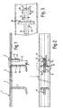
- the device 1 for securing a tread Scaffolding against unintentional lifting includes one edition 2 with safety hook 3, the holding means according to the invention represent.
- the pad 2 has a flat T-profile, in the Cross bar 4 a slot 5 for receiving an inventive Securing wedge 6 is provided.
- the safety wedge 6 is with a pin 7 against unintentional detachment from the support 2 secured, d. H. the locking wedge 6 caught in the slot 5.
- a U-profile 8 in in the immediate vicinity of a safety hook 9 so that the locking wedge 6 between the vertical section 10 of the Securing hook 9 and the crossbar 11 of the U-profile 8 therethrough fits.
- Fig. 2 or the representation acc. Fig. 3 is the U-profile 8 with its crossbar 11 and Side legs 12, 13 clearly recognizable.
- the safety wedge 6 is narrower than the distance between the side legs 12, 13, so that it is loosely guided in the U-profile 8.
- FIG. 4 is shown schematically how a fixing element 15 of a tread not shown a scaffolding in the form of a hook or a claw in the U-profile of a cross bar 16 of a scaffold is suspended.
- the support 2 rests on the fixing element 15 from above.
- the Crossbar 17 of the crossbar 16 are openings in the form of Elongated holes 18 are provided through which the horizontal section 14 a safety hook 3, 9 fits through.
- the Safety hook 3, 9 through the slot 18 is the Securing wedge 6 on the crosspiece 17 and is doing a little lifted up (see distance a) out of support 2.
- the elongated holes 18 are measured so that the locking wedge 6th after a sufficient shift V also by the Slot can pass through.
- the safety wedge 6 falls due to gravity automatically by the respective Slot 18.
- the stop surface 20 on the head 19 of the Securing wedge 6 strikes the crosspiece 4 of the Support rail 2.
- the safety wedge 6 has passed through the slot 18 is an opposite to the displacement V Shift essentially blocked, so that the Horizontal section 14 always the cross bar 17 of the cross bar 16th engages behind. A lifting of the support rail 2 from the crossbar 16 is therefore no longer possible, so the tread with its fixing elements 15 no longer inadvertently from the Crossbar 16 can be lifted off.
- the safety wedge To release the anti-lift device, the safety wedge must be used first 6 raised against gravity.
- the head 19 The safety wedge 6 is dimensioned so that it from can be gripped at the top and raised without the head 19th forms a tripping edge on the tread side of the treads.
- the anti-lift device 1 With the safety wedge 6, the anti-lift device 1 locked directly on the cross bar 16, the falling of the safety wedge 6 in the slot 18 after placing and Moving the anti-lift device clearly visible from above is, so that the secured condition is visually checked at all times can be.
- the formation of the ends of the anti-lift device 1 in Range of vertical not shown in the figures Scaffolding stand is therefore completely arbitrary.
- the Lifting protection does not match the length of the crossbar be adjusted.
- the slot 5 in the support rail or Head 19 of the locking wedge 6 designed so that the head of the Securing wedge 6 in the overlying state, the slot 5 at least partially closed.
- the U-shaped guide profile 8 is formed so long that with the support rail 2 still on, a certain distance d remains to the crossbar 17 of the cross bar 16 of the scaffolding. This ensures that the support rail 2 on the Fixing elements 15 or the associated tread rests, whereby this is secured against unintentional lifting is and not the guide profile 8 on the crosspiece 17 of the Cross bar 16 is present, which is a certain Freedom of movement of the fixing elements 15 between the Crossbar 16 and the support rail 2 could result.
- the safety wedge 6 For good guidance of the safety wedge 6, it is recommended that not make the U-profile much smaller than that Distance of the crosspiece 11 of the guide profile 8 from Vertical section 10 of the safety hook 9.
- the Distance between the legs 12, 13 of the U-profile 8, which in approximately parallel to the longitudinal edges of the slot 5 in the Support rail 2 are arranged, not larger than the two to two triple thickness of the locking wedge 6 selected.
- the Securing wedge 6 is thus in the transverse direction to the cross bar 16th through the legs 12, 13 and in the direction parallel to Crossbar 16 through the crossbar 11 and the vertical section 10 led.
- the length of the elongated holes 18 in the cross bar 16 or the slot 5 in the support rail 2 are advantageously measured so that the safety wedge 6 easily, but without major play through the holes 18 or slots 5 is to be inserted.
- the guide profile 8 is flush with the narrow end of the Slot 5 attached.
- the clear distance between the Vertical section 10 and the transverse web 11 of the guide profile 8 approximately the length of the slot 5 and at the same time approximately Length L of the safety wedge 6 in the area below the Head 19 with which the locking wedge 6 slits 5 in inserted state.
- the elongated hole 18 is preferably formed with a length the length of the locking wedge 6 in the area in which it in the inserted state, the slot 18 by 6 plus the corresponds to the corresponding thickness of the vertical section 10. On in this way the slot 18 is inserted Securing wedge 6 through the vertical section 10 and the Securing wedge 6 almost completely in the longitudinal direction closed, so that a horizontal movement possibility is reliably prevented.
Landscapes
- Engineering & Computer Science (AREA)
- Architecture (AREA)
- Mechanical Engineering (AREA)
- Civil Engineering (AREA)
- Structural Engineering (AREA)
- Ladders (AREA)
- Emergency Lowering Means (AREA)
- Forklifts And Lifting Vehicles (AREA)
- Movable Scaffolding (AREA)
- Suspension Of Electric Lines Or Cables (AREA)
Description
- Fig. 1
- eine schematische Schnittdarstellung durch eine erfindungsgemäße Aushebesicherung,
- Fig. 2
- eine Draufsicht auf eine Vorrichtung gem. Fig. 1,
- Fig. 3
- eine Ausschnittsvergrößerung aus Fig. 2 und
- Fig. 4
- eine Ausschnittsvergrößerung aus der Darstellung gem. Fig. 1.
- 1
- Vorrichtung
- 2
- Auflage
- 3
- Sicherungshaken
- 4
- Quersteg
- 5
- Ausnehmung
- 6
- Sicherungskeil
- 7
- Stift
- 8
- U-Profil
- 9
- Sicherungshaken
- 10
- Vertikalabschnitt
- 11
- Quersteg
- 12
- Schenkel
- 13
- Schenkel
- 14
- Horizontalabschnitt
- 15
- Fixierelement
- 16
- Querriegel
- 17
- Quersteg
- 18
- Langloch
- 19
- Kopf
- 20
- Anschlagfläche
Claims (13)
- Vorrichtung zur Aushebesicherung eines Laufbelags für ein Baugerüst, die eine obere Auflage (2) zum Auflegen auf ein oder mehrere an einem Querriegel (16) des Baugerüsts angebrachte Fixierelemente (15) des Laufbelags und den Querriegel in gesichertem Zustand wenigstens teilweise hintergreifende Haltemittel (3), (9) aufweist und Sicherungsmittel gegen ein unbeabsichtigtes Lösen der Haltemittel umfaßt, dadurch gekennzeichnet, daß die Sicherungsmittel (5), (6), (18) eine unmittelbar am Querriegel (16) angreifende Verriegelung umfassen.
- Vorrichtung nach Anspruch 1, dadurch gekennzeichnet, daß die Haltemittel (3), (9) den Querriegel (16) durch eine erste Verschiebung der Vorrichtung (1) in Bezug zum Querriegel mitsamt der Auflage (2) und den Haltemitteln (3), (9) hintergreifen und die Sicherungsmittel (6) eine gegenläufige zweite Verschiebung blockieren.
- Vorrichtung nach einem der vorgenannten Ansprüche, dadurch gekennzeichnet, daß die Auflage (2) als flache Auflageschiene ausgebildet ist.
- Vorrichtung nach einem der vorgenannten Ansprüche, dadurch gekennzeichnet, daß die Haltemittel wenigstens einen Sicherungshaken (3), (9) zum Durchstecken durch wenigstens ein Loch (18) im Querriegel (16) umfassen.
- Vorrichtung nach einem der vorgenannten Ansprüche, dadurch gekennzeichnet, daß die Sicherungsmittel einen in den Querriegel (16) einführbaren Sicherungskörper (6) umfassen.
- Vorrichtung nach einem der vorgenannten Ansprüche, dadurch gekennzeichnet, daß die Auflage (2) wenigstens eine Ausnehmung (5) zur Aufnahme des Sicherungskörpers (6) umfaßt.
- Vorrichtung nach einem der vorgenannten Ansprüche, dadurch gekennzeichnet, daß der Sicherungskörper (6) keilförmig ist.
- Vorrichtung nach einem der vorgenannten Ansprüche, dadurch gekennzeichnet, daß Führungsmittel (8), (10) für den Sicherungskörper (6) vorhanden sind.
- Vorrichtung nach einem der vorgenannten Ansprüche, dadurch gekennzeichnet, daß die Führungsmittel ein unterhalb der Auflage (2) angeordnetes U- oder C-förmiges Profil (8) umfassen.
- Vorrichtung nach einem der vorgenannten Ansprüche, dadurch gekennzeichnet, daß ein unterer Anschlag (7) vorgesehen ist, mittels dem der Sicherungskörper (6) in der Auflage (2) gegen unerwünschten Verlust gesichert ist.
- Vorrichtung nach einem der vorgenannten'Ansprüche, dadurch gekennzeichnet, daß der Sicherungskörper (6) einen Kopf (19) mit einem oberen Anschlag (20) aufweist, der den Sicherungskörper (6) gegen ein Durchfallen durch die Auflage (2) oder ein Verklemmen in der Auflage (2) sichert.
- Vorrichtung nach einem der vorgenannten Ansprüche, dadurch gekennzeichnet, daß der Kopf (19) in eingestecktem Zustand des Sicherungskörpers (6) eine parallel zur Oberseite der Auflage (2) verlaufende Anschlagfläche (20) aufweist.
- Baugerüst, dadurch gekennzeichnet, daß eine Vorrichtung nach einem der vorgenannten Ansprüche vorhanden ist.
Applications Claiming Priority (2)
| Application Number | Priority Date | Filing Date | Title |
|---|---|---|---|
| DE19717461 | 1997-04-25 | ||
| DE19717461A DE19717461C2 (de) | 1997-04-25 | 1997-04-25 | Vorrichtung zur Abhebesicherung eines Laufbelags für ein Baugerüst |
Publications (2)
| Publication Number | Publication Date |
|---|---|
| EP0874109A1 EP0874109A1 (de) | 1998-10-28 |
| EP0874109B1 true EP0874109B1 (de) | 2003-07-30 |
Family
ID=7827709
Family Applications (1)
| Application Number | Title | Priority Date | Filing Date |
|---|---|---|---|
| EP98104964A Expired - Lifetime EP0874109B1 (de) | 1997-04-25 | 1998-03-19 | Vorrichtung zur Abhebesicherung eines Laufbelags für ein Baugerüst |
Country Status (3)
| Country | Link |
|---|---|
| EP (1) | EP0874109B1 (de) |
| AT (1) | ATE246295T1 (de) |
| DE (2) | DE19717461C2 (de) |
Families Citing this family (3)
| Publication number | Priority date | Publication date | Assignee | Title |
|---|---|---|---|---|
| DE102008030602A1 (de) * | 2008-06-27 | 2009-12-31 | Wilhelm Layher Verwaltungs-Gmbh | Baugerüst mit Aushebesicherungsvorrichtung für Belageinheiten |
| DE102021130655A1 (de) * | 2021-11-23 | 2023-05-25 | Alfix Gmbh | Belagsicherungselement, Baugerüst und Verfahren zur Sicherung von Gerüstbelägen gegen Abheben |
| DE202023105452U1 (de) | 2023-09-19 | 2023-09-28 | Alfix Gmbh | Belagsicherungselement und Baugerüst hiermit |
Family Cites Families (5)
| Publication number | Priority date | Publication date | Assignee | Title |
|---|---|---|---|---|
| CH389225A (de) * | 1959-12-07 | 1965-03-15 | Huennebeck Emil Mauritz Dipl I | Klammer zum lösbaren Verbinden zweier Teile |
| DE1957466A1 (de) * | 1969-11-15 | 1971-06-16 | Heinz Reber | Geruesttraeger fuer ein Baugeruest |
| DE3020389A1 (de) * | 1980-05-29 | 1981-12-03 | geb. Layher Ruth 7129 Güglingen Langer | Abhubsicherung fuer baugerueste |
| FR2527251A1 (fr) * | 1982-05-18 | 1983-11-25 | Self Lock Echafaudages | Element de construction comportant une armature realisee au moyen de longerons et traverses, en particulier pour planchers d'echafaudage |
| US5145032A (en) * | 1990-11-13 | 1992-09-08 | Figgie International, Inc. | Mason's scaffold |
-
1997
- 1997-04-25 DE DE19717461A patent/DE19717461C2/de not_active Expired - Fee Related
-
1998
- 1998-03-19 DE DE59809121T patent/DE59809121D1/de not_active Expired - Fee Related
- 1998-03-19 AT AT98104964T patent/ATE246295T1/de not_active IP Right Cessation
- 1998-03-19 EP EP98104964A patent/EP0874109B1/de not_active Expired - Lifetime
Also Published As
| Publication number | Publication date |
|---|---|
| DE59809121D1 (de) | 2003-09-04 |
| EP0874109A1 (de) | 1998-10-28 |
| DE19717461C2 (de) | 2001-09-27 |
| DE19717461A1 (de) | 1998-10-29 |
| ATE246295T1 (de) | 2003-08-15 |
Similar Documents
| Publication | Publication Date | Title |
|---|---|---|
| EP4560092B1 (de) | Geländerpfosten für ein voreilendes geländer für ein gerüst, gerüst mit einem voreilenden geländer und verfahren zum umsetzen eines voreilenden geländers an einem gerüst | |
| DE4127252A1 (de) | Vorrichtung zur loesbaren befestigung eines geraetegehaeuses an einer profilschiene | |
| EP0003601A1 (de) | Roststab, insbesondere für mechanisch bewegte Schürroste von Grossfeuerungen | |
| EP0968861A2 (de) | Notausstiegsfenster eines Fahrzeuges mit Fensterglasscheibe | |
| DE19717461C2 (de) | Vorrichtung zur Abhebesicherung eines Laufbelags für ein Baugerüst | |
| EP2565328B1 (de) | Leitschwellenschranke sowie Fahrzeugrückhaltesystem mit einer Leitschwellenschranke | |
| DE3803223C1 (en) | Junction lock | |
| DE202006016486U1 (de) | Elektronikgehäuse | |
| DE102004027855B4 (de) | Schutzgitter mit griffförmiger Falle | |
| DE4206735C2 (de) | Vorrichtung zum Ein- oder Ausschleusen einer mit Gleitstücken, Röllchen o. dgl. Tragelementen versehenen Gardine an einer Gardinenleiste | |
| DE2849878C2 (de) | Einbruchsicherung für Gitterroste | |
| EP1762454B1 (de) | Vorrichtung in einem Weichenstellsystem zum mechanischen Verriegeln einer Weichenzunge | |
| DE19928574C2 (de) | Arbeitsbühne | |
| CH648812A5 (en) | Device for suspending at least one formwork panel on a lifting appliance | |
| DE4134028C2 (de) | Vorrichtung zur Verriegelung eines Abdeckrostes an einem Rahmen | |
| DE3207497C2 (de) | ||
| DE3941386A1 (de) | Kragarm-regal | |
| DE2525475C2 (de) | Begehbare Graböffnungssicherung | |
| DE3907424C2 (de) | ||
| EP4183951B1 (de) | Belagsicherungselement, baugerüst und verfahren zur sicherung von gerüstbelägen gegen abheben | |
| DE8029405U1 (de) | Aufhaengevorrichtung | |
| DE4310638C2 (de) | Befestigung des Sockels eines Kabelverteilerschrankes auf einer gitterrostförmigen Bodenplatte, mit mindestens einer in die Bodenplatte eingedrückten Klammer | |
| DE9416670U1 (de) | Winkelförmiger Pfosten für einen Gleis-Sicherungszaun | |
| DE29900115U1 (de) | Ringeleinsatz für die Eckstücke von Containern | |
| DE102023112162A1 (de) | Leiter |
Legal Events
| Date | Code | Title | Description |
|---|---|---|---|
| PUAI | Public reference made under article 153(3) epc to a published international application that has entered the european phase |
Free format text: ORIGINAL CODE: 0009012 |
|
| AK | Designated contracting states |
Kind code of ref document: A1 Designated state(s): AT BE CH DE DK ES FR GB IT LI NL PT |
|
| AX | Request for extension of the european patent |
Free format text: AL;LT;LV;MK;RO;SI |
|
| 17P | Request for examination filed |
Effective date: 19990128 |
|
| AKX | Designation fees paid |
Free format text: AT BE CH DE DK ES FR GB IT LI NL PT |
|
| RAP1 | Party data changed (applicant data changed or rights of an application transferred) |
Owner name: ASSCO GERUESTE GMBH & CO. |
|
| RAP1 | Party data changed (applicant data changed or rights of an application transferred) |
Owner name: PLETTACH ASSCO GMBH & CO. KG. |
|
| RAP3 | Party data changed (applicant data changed or rights of an application transferred) |
Owner name: PLETTAC ASSCO GMBH & CO. KG. |
|
| GRAH | Despatch of communication of intention to grant a patent |
Free format text: ORIGINAL CODE: EPIDOS IGRA |
|
| GRAH | Despatch of communication of intention to grant a patent |
Free format text: ORIGINAL CODE: EPIDOS IGRA |
|
| GRAA | (expected) grant |
Free format text: ORIGINAL CODE: 0009210 |
|
| AK | Designated contracting states |
Designated state(s): AT BE CH DE DK ES FR GB IT LI NL PT |
|
| PG25 | Lapsed in a contracting state [announced via postgrant information from national office to epo] |
Ref country code: NL Free format text: LAPSE BECAUSE OF FAILURE TO SUBMIT A TRANSLATION OF THE DESCRIPTION OR TO PAY THE FEE WITHIN THE PRESCRIBED TIME-LIMIT Effective date: 20030730 Ref country code: IT Free format text: LAPSE BECAUSE OF FAILURE TO SUBMIT A TRANSLATION OF THE DESCRIPTION OR TO PAY THE FEE WITHIN THE PRESCRIBED TIME-LIMIT;WARNING: LAPSES OF ITALIAN PATENTS WITH EFFECTIVE DATE BEFORE 2007 MAY HAVE OCCURRED AT ANY TIME BEFORE 2007. THE CORRECT EFFECTIVE DATE MAY BE DIFFERENT FROM THE ONE RECORDED. Effective date: 20030730 Ref country code: GB Free format text: LAPSE BECAUSE OF FAILURE TO SUBMIT A TRANSLATION OF THE DESCRIPTION OR TO PAY THE FEE WITHIN THE PRESCRIBED TIME-LIMIT Effective date: 20030730 Ref country code: FR Free format text: LAPSE BECAUSE OF NON-PAYMENT OF DUE FEES Effective date: 20030730 |
|
| REG | Reference to a national code |
Ref country code: GB Ref legal event code: FG4D Free format text: NOT ENGLISH |
|
| REG | Reference to a national code |
Ref country code: CH Ref legal event code: EP |
|
| REF | Corresponds to: |
Ref document number: 59809121 Country of ref document: DE Date of ref document: 20030904 Kind code of ref document: P |
|
| PG25 | Lapsed in a contracting state [announced via postgrant information from national office to epo] |
Ref country code: DK Free format text: LAPSE BECAUSE OF FAILURE TO SUBMIT A TRANSLATION OF THE DESCRIPTION OR TO PAY THE FEE WITHIN THE PRESCRIBED TIME-LIMIT Effective date: 20031030 |
|
| PG25 | Lapsed in a contracting state [announced via postgrant information from national office to epo] |
Ref country code: ES Free format text: LAPSE BECAUSE OF FAILURE TO SUBMIT A TRANSLATION OF THE DESCRIPTION OR TO PAY THE FEE WITHIN THE PRESCRIBED TIME-LIMIT Effective date: 20031110 |
|
| NLV1 | Nl: lapsed or annulled due to failure to fulfill the requirements of art. 29p and 29m of the patents act | ||
| PG25 | Lapsed in a contracting state [announced via postgrant information from national office to epo] |
Ref country code: PT Free format text: LAPSE BECAUSE OF FAILURE TO SUBMIT A TRANSLATION OF THE DESCRIPTION OR TO PAY THE FEE WITHIN THE PRESCRIBED TIME-LIMIT Effective date: 20031230 |
|
| GBV | Gb: ep patent (uk) treated as always having been void in accordance with gb section 77(7)/1977 [no translation filed] |
Effective date: 20030730 |
|
| PG25 | Lapsed in a contracting state [announced via postgrant information from national office to epo] |
Ref country code: AT Free format text: LAPSE BECAUSE OF NON-PAYMENT OF DUE FEES Effective date: 20040319 |
|
| PG25 | Lapsed in a contracting state [announced via postgrant information from national office to epo] |
Ref country code: LI Free format text: LAPSE BECAUSE OF NON-PAYMENT OF DUE FEES Effective date: 20040331 Ref country code: CH Free format text: LAPSE BECAUSE OF NON-PAYMENT OF DUE FEES Effective date: 20040331 Ref country code: BE Free format text: LAPSE BECAUSE OF NON-PAYMENT OF DUE FEES Effective date: 20040331 |
|
| PLBE | No opposition filed within time limit |
Free format text: ORIGINAL CODE: 0009261 |
|
| STAA | Information on the status of an ep patent application or granted ep patent |
Free format text: STATUS: NO OPPOSITION FILED WITHIN TIME LIMIT |
|
| 26N | No opposition filed |
Effective date: 20040504 |
|
| EN | Fr: translation not filed | ||
| BERE | Be: lapsed |
Owner name: *PLETTAC ASSCO G.M.B.H. & CO. K.G. Effective date: 20040331 |
|
| PG25 | Lapsed in a contracting state [announced via postgrant information from national office to epo] |
Ref country code: DE Free format text: LAPSE BECAUSE OF NON-PAYMENT OF DUE FEES Effective date: 20041001 |
|
| REG | Reference to a national code |
Ref country code: CH Ref legal event code: PL |