EP0872355A2 - Ladevorrichtung für eine Tintenkassette in einem Drucker und Drucker mit einer solchen Ladevorrichtung - Google Patents
Ladevorrichtung für eine Tintenkassette in einem Drucker und Drucker mit einer solchen Ladevorrichtung Download PDFInfo
- Publication number
- EP0872355A2 EP0872355A2 EP98106055A EP98106055A EP0872355A2 EP 0872355 A2 EP0872355 A2 EP 0872355A2 EP 98106055 A EP98106055 A EP 98106055A EP 98106055 A EP98106055 A EP 98106055A EP 0872355 A2 EP0872355 A2 EP 0872355A2
- Authority
- EP
- European Patent Office
- Prior art keywords
- ink cartridge
- ink
- receptacle
- loading mechanism
- printer
- Prior art date
- Legal status (The legal status is an assumption and is not a legal conclusion. Google has not performed a legal analysis and makes no representation as to the accuracy of the status listed.)
- Granted
Links
Images


Classifications
-
- B—PERFORMING OPERATIONS; TRANSPORTING
- B41—PRINTING; LINING MACHINES; TYPEWRITERS; STAMPS
- B41J—TYPEWRITERS; SELECTIVE PRINTING MECHANISMS, i.e. MECHANISMS PRINTING OTHERWISE THAN FROM A FORME; CORRECTION OF TYPOGRAPHICAL ERRORS
- B41J2/00—Typewriters or selective printing mechanisms characterised by the printing or marking process for which they are designed
- B41J2/005—Typewriters or selective printing mechanisms characterised by the printing or marking process for which they are designed characterised by bringing liquid or particles selectively into contact with a printing material
- B41J2/01—Ink jet
- B41J2/17—Ink jet characterised by ink handling
- B41J2/175—Ink supply systems ; Circuit parts therefor
- B41J2/17503—Ink cartridges
- B41J2/1752—Mounting within the printer
-
- B—PERFORMING OPERATIONS; TRANSPORTING
- B41—PRINTING; LINING MACHINES; TYPEWRITERS; STAMPS
- B41J—TYPEWRITERS; SELECTIVE PRINTING MECHANISMS, i.e. MECHANISMS PRINTING OTHERWISE THAN FROM A FORME; CORRECTION OF TYPOGRAPHICAL ERRORS
- B41J25/00—Actions or mechanisms not otherwise provided for
- B41J25/34—Bodily-changeable print heads or carriages
Definitions
- the present invention relates to an ink cartridge loading mechanism for a printer comprising an ink jet head section and to a printer having such a loading mechanism.
- Printers which comprise an ink jet head section wherein an ink cartridge is used to supply ink to the ink jet head section.
- An ink cartridge loading mechanism comprises an ink supply needle placed at a fixed position and an ink cartridge is placed in such a manner that the ink supply needle is inserted into an ink supply port of the ink cartridge.
- An ink cartridge of the structure disclosed in Japanese Laid-Open Patent No. Hei 5-16378 by the present applicant is known.
- This ink cartridge consists of a flexible ink bag in which ink is sealed, an ink supply port leading from the ink bag, and a hard plastic case containing the ink bag.
- the plastic case is shaped like a flat rectangular parallelopiped and the ink supply port leading from the ink bag is exposed to the front end face of the plastic case. Therefore, the ink cartridge is placed in such a manner that the ink supply needle of the printer is inserted into the ink supply port of the ink cartridge.
- the ink cartridge To insert the ink supply needle into the ink supply port in an appropriate fashion and attach the ink supply needle, the ink cartridge needs to be moved in a sliding fashion in the direction of the needle.
- an ink cartridge loading part is disposed in the front or rear portion of the printer and the ink cartridge is slidable horizontally from the front or rear side, whereby it can be attached or detached.
- the printer cannot be installed near or on a wall. In such a case, even if the footprint of the printer itself is small, a large installation space for the printer is nonetheless required.
- a printer adapted to replace an ink cartridge therein from the front accessories and other equipment related to the printer cannot be placed on the front face of the printer.
- input units such as a tablet, a keyboard, and a scanner and a display unit for displaying data, etc., entered through the input units may be placed in front of the printer.
- the printer adapted to replace an ink cartridge therein from the front requires that the accessories should be moved away when an ink cartridge is replaced; such an arrangement is not preferred from the viewpoint of ease of use.
- the conventional printer's ink cartridge loading mechanism involves solving the problems that the printer installation area is restricted in size but that a large printer installation space is required. It is therefore an object of the invention to provide an ink cartridge loading mechanism for a printer that requires less space than the known devices.
- the invention comprises an ink cartridge loading or placement mechanism for an ink jet head device that is formed so as to allow an ink cartridge to be inserted from a direction different from the axial direction of the ink supply needle which is disposed in an ink cartridge loading or reloading section of a printer, and then to be moved toward the ink supply needle, thereby lessening the space required for placing or replacing the ink cartridge as compared with placing the ink cartridge from the same direction as the ink supply needle as in the prior art.
- an ink cartridge loading mechanism for a printer. It comprises a loading section for detachably arranging an ink cartridge and an ink supply needle disposed in the loading section.
- the ink cartridge in the loading section is arranged in such a manner that the ink supply needle is inserted into an ink supply port of the ink cartridge.
- the loading section further comprises a receptacle section for accepting the ink cartridge from a direction different from the axial direction of the ink supply needle.
- the ink supply needle can be inserted into the ink supply port by using a slide mechanism for causing the receptacle section to reciprocate in the axial direction of the ink supply needle.
- the direction in which the receptacle section accepts the ink cartridge is a direction roughly orthogonal to the axial direction of the ink supply needle.
- it can also be a direction forming an acute angle or an obtuse angle rather than the orthogonal direction.
- the slide mechanism can comprise a guide frame for slidably supporting the receptacle section, an operation lever formed pivotably on the side of the guide frame, and a mechanism for converting rotation of the operation lever into linear motion sliding the receptacle section.
- the slide mechanism can comprise a guide frame for slidably supporting the receptacle section, a rack formed on the side of the receptacle section, a pinion being formed on the side of the guide frame and engaging the rack, and an operation lever extending radially from the rotation center of the pinion for rotating the pinion. If the slide mechanism is used, the receptacle section is easily slidable by a small force by lengthening the operation lever.
- the slide mechanism comprising a guide frame for slidably supporting the receptacle section, a protrusion formed on the side of the receptacle section, and an operation lever being formed on the side of the guide frame and engaging the protrusion for sliding the receptacle section
- the slide mechanism comprising a guide frame for slidably supporting the receptacle section, a groove-like cam formed on the side of the receptacle section, and an operation lever being formed on the side of the guide frame and having a protrusion engaging the cam can be used to slide the receptacle section.
- the above-described ink cartridge disclosed in Japanese Laid-Open Patent No. Hei 5-16378 previously proposed by the present applicant can be used as the placed ink cartridge.
- the ink cartridge comprises a flexible ink bag in which ink is sealed, an ink supply port provided in the ink bag, and a hard case containing the ink bag.
- the ink supply needle is placed horizontally so as to decrease any ink leakage.
- the ink cartridge loading mechanism can also include the lid to block the opening into the receptacle section in a state in which the lid can be opened in the ink cartridge acceptance direction, a spring for energizing or biasing the lid in the direction for blocking the opening, and an engagement section for holding the lid in the blocking state, and if the engagement section can be moved in a direction so that the engagement is released as the ink cartridge is pushed into the receptacle section, the lid is then opened or closed in association with the attachment or detachment of the ink cartridge.
- FIG. 1 and FIG. 2 are perspective views of an ink jet printer incorporating the invention from the front and rear thereof, respectively, in a slanting direction.
- FIG. 3 is a schematic representation to show an outline of a paper transport passage in the ink jet printer.
- an ink jet printer 1 comprises a roll paper loading mechanism 2 and a paper feed port 3 of cut paper, slip paper, and the like, of any size, such as A4 or the like, and a transport passage is formed so that roll paper 4 supplied from the roll paper loading mechanism 2 and slip paper 5 inserted from the paper feed port 3 are transported through a print position 11 (area surrounded by the alternate long and short dashed line in FIG. 1).
- An ink jet head 8 is carried by a carriage mechanism 9 so as to face the surface of the roll paper 4 or slip paper 5 passed through the print position 11.
- the carriage mechanism 9 comprises a guide shaft 6, a carriage 7 carried along the guide shaft 6 for a reciprocating motion in a direction orthogonal to the transport direction of the roll paper 4 and the slip paper 5, and a carriage driving motor (not shown).
- the carriage 7 can reciprocate in the range which includes the print position 11 in the width direction thereof.
- a capping face 11C of a capping mechanism 11B which is a retreat position of the ink jet 8, is placed at a position out of the print position 11 to one side in the width direction.
- the ink jet head 8 has the nozzle face closed by the capping face 11C for preventing the ink meniscus of each ink nozzle from receding, ink from drying, and the like.
- Ink is supplied to the ink jet head 8 via an ink tube (not shown) from an ink cartridge loading mechanism 10 as an ink supply section mounted at a position adjoining the roll paper loading mechanism 2.
- the ink cartridge loading mechanism 10 comprises an ink cartridge loading section 30 in which an ink cartridge 20 is placed detachably.
- an ink supply channel for supplying ink to the ink jet head 8 will be outlined.
- An ink supply needle 31 is placed in the ink cartridge loading section 30 of the ink cartridge loading mechanism 10, and the ink cartridge 20 is placed so that the ink supply needle 31 is completely inserted.
- Ink supplied from the ink cartridge 20 to the ink supply needle 31 is supplied through an ink tube 32 to the ink jet head 8.
- the ink jet head 8 is driven, whereby ink drops are jetted from ink nozzles (not shown) onto recording paper transporting through the print position 11.
- an ink pump 33 is driven, whereby ink can be sucked from the nozzle face and be collected in a waste ink collection section 35 via a waste ink tube 34.
- the ink cartridge 20 comprises a flexible ink bag 21 in which ink is sealed, an ink supply made in the ink bag 21, and a hard case 23 containing the ink bag 21.
- the case 23 consists of a case main body 23a and a case lid 23b.
- Made in the front end face 23c of the case 23 are a needle insertion hole 23d through which the ink supply needle 31 can be inserted into the ink supply from the outside of the case 23 and three ink cartridge positioning holes 23e.
- a detection plate 24 for detecting the remaining ink amount is attached to the side face of the ink bag 21.
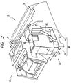
- FIG. 5A and FIG. 5B illustrate a state of the ink cartridge loading mechanism 10 before the ink cartridge 20 is placed therein.
- FIG. 6A and FIG. 6B show a state before and a state after the ink cartridge 20 is placed into contact with the ink supply needle 31 by a slide mechanism 60.
- the ink cartridge loading mechanism 10 comprises the ink cartridge loading section 30 for detachably placing the ink cartridge 20 therein.
- the loading section 30 comprises a hood section 40 having a side face to which the ink supply needle 31 is horizontally attached with the tip side of the ink supply needle 31 in an open state. Three positioning pins 42 project from the side face of the hood section 40 horizontally in the same direction as the ink supply needle 31.
- the loading section 30 comprises a box-shaped ink cartridge receptacle section 50 that can slide to the hood section 40 in the axial direction of the ink supply needle 31, namely, in the horizonal direction. It further comprises a slide mechanism 60 for sliding the receptacle section 50 in the horizontal direction.
- the box-shaped receptacle section 50 has an opening 51 on the top and the ink cartridge 20 can be placed in the receptacle section 50 in the vertical direction from the top of the upper opening 51. That is, the ink cartridge 20 can be accepted from the direction roughly orthogonal to the ink supply needle 31.
- the receptacle section 50 is formed on a front end face 52 with an opening 52d and positioning holes 52e at the positions matching the needle insertion hole 23d and the three ink cartridge positioning holes 23e made in the front end face 23 of the ink cartridge 20.
- a lid 53 is attached to the upper opening 51 of the receptacle section 50. It can pivot downward (in the ink cartridge acceptance direction) about a pivot 53a on one side of the receptacle section 50 and is normally biased in the direction of closing the lid 53 by a spring force.
- the lid 53 When the lid 53 is closed, the tip thereof is fitted into an engagement groove 54 made on the side face of the receptacle section 50 in a locked state.
- a protrusion 25 that can move the engagement groove 54 in a lateral direction is formed on the bottom side face of the ink cartridge 20. Therefore, if the ink cartridge 20 is pushed from the top thereof, the protrusion 25 causes the formation portion of the engagement groove 54 to elastically move, unlocking the lid.
- the lid 53 pivots downward together with the ink cartridge 20 and is pushed against the side face of the receptacle section 50.
- the lid 53 pivots upward by a spring force accordingly and again is restored to the locked state shown in FIG. 5B.
- the slide mechanism 60 for sliding the receptacle section 50 has a guide frame 61 slidably supporting the receptacle section 50 and the guide frame 61 is formed with a rail groove 62 into which a guide rail 56 formed along the bottom face of the receptacle section 50 is fitted slidably.
- a rack 63 is formed on the side face of the receptacle section 50 downward toward the slide direction.
- a pinion 64 is rotatably attached to the side of the guide frame 61 in an engagement state with the rack 63.
- An operation lever 65 extends to the side face of the pinion 64 almost radially from a pivot center 66 of the pinion 64.
- the ink cartridge 20 is pushed into the upper opening 53 of the receptacle section 50 as indicated by the arrow from the top.
- the lid 53 is pushed inwardly and opened, allowing the ink cartridge 20 to be accepted therein.
- the needle hole 23d and the three positioning holes 23e made in the front end face 23 of the ink cartridge 20 match the opening 52d and the three positioning holes 52e made in the front end face of the receptacle section 50, respectively.
- the operation lever 65 When the operation lever 65 is completely raised, the front end face 52 of the receptacle section 50 abuts the side face of the hood section 40. As operation lever 65 is raised, the three positioning pins 42 are inserted into the positioning holes 52e in the front end face of the receptacle section and the positioning holes 23e in the front end face of the ink cartridge, so that the ink cartridge 20 is guided and positioned by the positioning pins 42.
- the ink supply needle 31 projecting horizontally also passes through the opening 52d in the front end face of the receptacle section and the needle hole 23d in the front end face of the ink cartridge 20 and is completely inserted into the ink supply port 22 inside the ink cartridge. As a result, the ink supply channel from the ink cartridge 20 to the ink jet head 8 is completed.
- the operation may be reversed. That is, the operation lever 65 in the position shown in FIG. 6B is rotated counterclockwise, towards the rear of the device. As a result, the receptacle section 50 slides to the rear and the upper opening 53 thereof is completely drawn out from the hood section 40. That is, the position shown in FIG. 6A results. After this, both side faces of the ink cartridge 20 exposed from notches 57a and 57b made in both side faces of the receptacle section 50 may be grasped and be drawn out upward, which is perpendicularly to the sliding direction resulting from the rotation of operation lever 65.
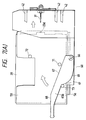
- FIG. 7A and FIG. 7B show a position before and a position after an ink cartridge 20 slides to the side of the device toward an ink supply needle 31 by the action of a slide mechanism. Parts identical with or similar to those previously described with reference to FIG. 5 and FIG. 6 are denoted by the same reference numerals in FIG. 7 and will not be discussed again.
- Protrusions 71, 72, and 73 are formed on the side face of an ink cartridge receptacle section 50 of the ink cartridge loading mechanism of the embodiment. They are placed at proper positions on the side face of the ink cartridge receptacle section 50 so that when an operation lever 65b is pivoted with a pivot center 66 as a supporting point, it abuts the protrusions 71, 72, and 73 and pushes them, whereby the ink cartridge receptacle section 50 moves horizontally.
- a slide mechanism 60 for sliding the receptacle section 50 has a guide frame 61 slidably supporting the receptacle section 50 and the guide frame 61 is formed with a rail groove 62 into which a guide rail 56 formed along the bottom face of the receptacle section 50 is fitted slidably, as in the first embodiment.
- FIG. 7A shows a state in which the ink cartridge receptacle section 50 is drawn out from a hood section 40 and the ink cartridge 20 is placed into ink cartridge receptacle section 50 from the top.
- the operation lever 65b illustrated as falling to the side, is rotated upward, whereby the receptacle section 50 in which the ink cartridge 20 is placed slides horizontally toward the side having the ink supply needle 31.
- three positioning pins 42 are inserted into positioning holes 52e in the front end face of the receptacle section and positioning holes 23e in the front end face of the ink cartridge, as in the first embodiment.
- the operation is reversed. That is, the operation lever 65b in the position shown in FIG. 7B is rotated counterclockwise, towards the rear of the device. As a result a side face 69 opposed to the side face 67 of the operation lever 65b pushes the protrusion 73 for sliding the receptacle section 50 to the rear. If the operation lever 65b is completely brought down, an upper opening 53 of the receptacle section 50 is completely drawn out from the hood section 40. That is, the position shown in FIG. 7A results.
- both side faces of the ink cartridge 20 exposed from notches 57a and 57b made in both side faces of the receptacle section 50 may be grasped and be drawn out upward, which is perpendicularly to the sliding direction resulting from the rotation of operation lever 65.
- the cartridge receptacle section is formed with the protrusions and the operation lever pushes the protrusions for sliding the cartridge receptacle section.
- the operation lever may be formed with a protrusion (cam follower) and the cartridge receptacle section may be formed with a groove-like cam engaging the protrusion, so that a mechanism of sliding the cartridge receptacle section in response to rotation of the operation lever may be used to convert the rotation of the operation lever into linear motion sliding the cartridge receptacle section.
- an ink cartridge is placed from a direction different from the direction of alignment of ink supply needle and then is slidingly moved toward the direction of the ink supply needle, thereby completing loading of the ink cartridge.
- the space in the loading direction can be lessened as compared with the loading mechanism for placing an ink cartridge from one direction as in the prior art.
- a printer comprising the ink cartridge loading mechanism of the invention does not require a large space on the front or rear side of the printer, there are fewer restrictions on the location of the printer and the printer does not require a large amount of space to accommodate replacing the ink cartridge.
Landscapes
- Ink Jet (AREA)
- Impression-Transfer Materials And Handling Thereof (AREA)
Applications Claiming Priority (3)
| Application Number | Priority Date | Filing Date | Title |
|---|---|---|---|
| JP8423597 | 1997-04-02 | ||
| JP8423597 | 1997-04-02 | ||
| JP84235/97 | 1997-04-02 |
Publications (3)
| Publication Number | Publication Date |
|---|---|
| EP0872355A2 true EP0872355A2 (de) | 1998-10-21 |
| EP0872355A3 EP0872355A3 (de) | 2000-04-12 |
| EP0872355B1 EP0872355B1 (de) | 2004-01-02 |
Family
ID=13824819
Family Applications (1)
| Application Number | Title | Priority Date | Filing Date |
|---|---|---|---|
| EP98106055A Expired - Lifetime EP0872355B1 (de) | 1997-04-02 | 1998-04-02 | Ladevorrichtung für eine Tintenkassette in einem Drucker und Drucker mit einer solchen Ladevorrichtung |
Country Status (6)
| Country | Link |
|---|---|
| US (1) | US5971534A (de) |
| EP (1) | EP0872355B1 (de) |
| KR (1) | KR100525852B1 (de) |
| CN (1) | CN1094427C (de) |
| AT (1) | ATE257088T1 (de) |
| DE (1) | DE69820808T2 (de) |
Cited By (8)
| Publication number | Priority date | Publication date | Assignee | Title |
|---|---|---|---|---|
| FR2776229A1 (fr) * | 1998-03-18 | 1999-09-24 | Tally Computerdrucker Gmbh | Imprimante a encre comportant au moins un reservoir interchangeable pour l'encre devant etre amenee dans un ou plusieurs recipients de stockage |
| EP0956965A3 (de) * | 1998-05-13 | 2000-08-09 | Seiko Epson Corporation | Tintenkassette für Tintenstrahlaufzeichnungsvorrichtung |
| EP1013434A3 (de) * | 1998-12-14 | 2000-08-30 | SCITEX DIGITAL PRINTING, Inc. | Vorrichtung zum Einbauen und Befestigen eines Druckkopfes |
| EP1125747A3 (de) * | 2000-02-16 | 2002-11-20 | Seiko Epson Corporation | Tintenpatrone für Tintenstrahlaufzeichnungsvorrichtung, Anschlusseinheit und Tintenstrahlaufzeichnungsvorrichtung |
| GB2409435A (en) * | 2003-12-22 | 2005-06-29 | Seiko Epson Corp | An ink cartridge mounting device having a rotating and sliding mechanism |
| EP1707378A1 (de) * | 2005-03-28 | 2006-10-04 | Seiko Epson Corporation | Vorrichtung zur Befestigung/ Entfernung einer Tintenpatrone, Aufzeichnungsgerät und Flüssigkeitsausstossgerät |
| WO2006104242A1 (en) * | 2005-03-28 | 2006-10-05 | Seiko Epson Corporation | Liquid cartridge, loading/unloading device of liquid cartridge, recording apparatus, and liquid ejection apparatus |
| EP1721745A3 (de) * | 2005-05-11 | 2008-02-27 | Seiko Epson Corporation | Vorrichtung zur Befestigung/ Entfernung einer Farbstoffkassette, Aufzeichnungsgerät und Flüssigkeitausstossgerät |
Families Citing this family (12)
| Publication number | Priority date | Publication date | Assignee | Title |
|---|---|---|---|---|
| AUPS048802A0 (en) * | 2002-02-13 | 2002-03-07 | Silverbrook Research Pty. Ltd. | Methods and systems (ap48) |
| TWI280196B (en) * | 2005-10-21 | 2007-05-01 | Lite On Technology Corp | Ink cartridge loading mechanism |
| CN100436141C (zh) * | 2005-11-04 | 2008-11-26 | 光宝科技股份有限公司 | 墨盒承载机构及具有墨盒和承载机构的组合结构 |
| JP4277850B2 (ja) * | 2005-11-30 | 2009-06-10 | ブラザー工業株式会社 | リフィルユニット |
| JP4466872B2 (ja) * | 2006-01-11 | 2010-05-26 | セイコーエプソン株式会社 | インクカートリッジの着脱装置、記録装置及び液体噴射装置 |
| JP4697453B2 (ja) * | 2006-06-29 | 2011-06-08 | セイコーエプソン株式会社 | カートリッジの着脱装置、記録装置及び液体噴射装置 |
| CN101279537B (zh) * | 2007-04-03 | 2010-06-23 | 明基电通股份有限公司 | 喷墨打印装置 |
| US8231209B2 (en) * | 2008-03-25 | 2012-07-31 | Seiko Epson Corporation | Liquid jetting system, liquid container, holder, and liquid jetting apparatus having holder |
| CN101873936B (zh) | 2008-09-29 | 2012-06-06 | 株式会社理光 | 墨水盒和成像设备 |
| EP2397331B1 (de) * | 2010-06-17 | 2014-07-23 | Brother Kogyo Kabushiki Kaisha | Satz von Tintenpatronen |
| JP5162652B2 (ja) * | 2010-12-20 | 2013-03-13 | 富士ゼロックス株式会社 | 液体供給装置 |
| US8596771B2 (en) * | 2011-03-30 | 2013-12-03 | Brother Kogyo Kabushiki Kaisha | Printing-liquid cartridge and recording apparatus using the same |
Citations (7)
| Publication number | Priority date | Publication date | Assignee | Title |
|---|---|---|---|---|
| JPS60204344A (ja) * | 1984-03-30 | 1985-10-15 | Canon Inc | 液体噴射記録装置 |
| EP0379151A2 (de) * | 1989-01-17 | 1990-07-25 | Canon Kabushiki Kaisha | Tintenstrahldruckvorrichtung und Verfahren zum Einbau eines Tintenstrahldruckkopfes in eine Tintenstrahldruckvorrichtung |
| JPH03197052A (ja) * | 1989-12-26 | 1991-08-28 | Canon Inc | インクカートリッジおよびそのインクカートリッジの装着が可能なインクジェット記録装置 |
| JPH0410947A (ja) * | 1990-04-27 | 1992-01-16 | Sharp Corp | インクジェット記録ヘッドの目詰まり防止装置 |
| JPH0516378A (ja) * | 1991-07-08 | 1993-01-26 | Seiko Epson Corp | インクカートリツジ |
| US5359357A (en) * | 1992-03-19 | 1994-10-25 | Fuji Xerox Co., Ltd. | Ink-jet recording apparatus |
| EP0715959A2 (de) * | 1991-12-11 | 1996-06-12 | Canon Kabushiki Kaisha | Tintenstrahlaufzeichnungsgerät und Verfahren zur Montage eines Tintenstrahlaufzeichnungskopfes |
Family Cites Families (2)
| Publication number | Priority date | Publication date | Assignee | Title |
|---|---|---|---|---|
| JPH0516377A (ja) * | 1991-07-08 | 1993-01-26 | Seiko Epson Corp | インクカートリツジ |
| DE4133108A1 (de) * | 1991-10-05 | 1993-04-08 | Philips Patentverwaltung | Elektrischer rotations- oder linearmotor, dessen laeufer mittels ultraschallschwingungen angetrieben wird |
-
1998
- 1998-04-02 DE DE69820808T patent/DE69820808T2/de not_active Expired - Fee Related
- 1998-04-02 KR KR10-1998-0011602A patent/KR100525852B1/ko not_active IP Right Cessation
- 1998-04-02 AT AT98106055T patent/ATE257088T1/de not_active IP Right Cessation
- 1998-04-02 CN CN98106208A patent/CN1094427C/zh not_active Expired - Fee Related
- 1998-04-02 EP EP98106055A patent/EP0872355B1/de not_active Expired - Lifetime
- 1998-04-02 US US09/054,139 patent/US5971534A/en not_active Expired - Lifetime
Patent Citations (7)
| Publication number | Priority date | Publication date | Assignee | Title |
|---|---|---|---|---|
| JPS60204344A (ja) * | 1984-03-30 | 1985-10-15 | Canon Inc | 液体噴射記録装置 |
| EP0379151A2 (de) * | 1989-01-17 | 1990-07-25 | Canon Kabushiki Kaisha | Tintenstrahldruckvorrichtung und Verfahren zum Einbau eines Tintenstrahldruckkopfes in eine Tintenstrahldruckvorrichtung |
| JPH03197052A (ja) * | 1989-12-26 | 1991-08-28 | Canon Inc | インクカートリッジおよびそのインクカートリッジの装着が可能なインクジェット記録装置 |
| JPH0410947A (ja) * | 1990-04-27 | 1992-01-16 | Sharp Corp | インクジェット記録ヘッドの目詰まり防止装置 |
| JPH0516378A (ja) * | 1991-07-08 | 1993-01-26 | Seiko Epson Corp | インクカートリツジ |
| EP0715959A2 (de) * | 1991-12-11 | 1996-06-12 | Canon Kabushiki Kaisha | Tintenstrahlaufzeichnungsgerät und Verfahren zur Montage eines Tintenstrahlaufzeichnungskopfes |
| US5359357A (en) * | 1992-03-19 | 1994-10-25 | Fuji Xerox Co., Ltd. | Ink-jet recording apparatus |
Non-Patent Citations (4)
| Title |
|---|
| PATENT ABSTRACTS OF JAPAN vol. 10, no. 55 (M-458) [2112], 5 March 1986 (1986-03-05) & JP 60 204344 A (CANON K.K.), 15 October 1985 (1985-10-15) * |
| PATENT ABSTRACTS OF JAPAN vol. 15, no. 458 (M-1182), 21 November 1991 (1991-11-21) & JP 03 197052 A (CANON INC), 28 August 1991 (1991-08-28) * |
| PATENT ABSTRACTS OF JAPAN vol. 16, no. 161 (M-1237), 20 April 1992 (1992-04-20) & JP 04 010947 A (SHARP CORP), 16 January 1992 (1992-01-16) * |
| PATENT ABSTRACTS OF JAPAN vol. 17, no. 286 (M-1422), 2 June 1993 (1993-06-02) & JP 05 016378 A (SEIKO EPSON CORP), 26 January 1993 (1993-01-26) * |
Cited By (35)
| Publication number | Priority date | Publication date | Assignee | Title |
|---|---|---|---|---|
| US6315401B1 (en) | 1998-03-18 | 2001-11-13 | Tally Computerdrucker Gmbh | Ink printer with at least one exchangeable tank for ink to be supplied to one or more reservoirs |
| GB2339171A (en) * | 1998-03-18 | 2000-01-19 | Tally Computerdrucker Gmbh | Cam lever mechanism for moving a replaceable ink tank to displace a sprung cover plate and form a coupling between the tank and an ink supply needle |
| FR2776229A1 (fr) * | 1998-03-18 | 1999-09-24 | Tally Computerdrucker Gmbh | Imprimante a encre comportant au moins un reservoir interchangeable pour l'encre devant etre amenee dans un ou plusieurs recipients de stockage |
| GB2339171B (en) * | 1998-03-18 | 2002-04-03 | Tally Computerdrucker Gmbh | Replaceable ink tanks for printers |
| US6755515B2 (en) | 1998-05-13 | 2004-06-29 | Seiko Epson Corporation | Ink cartridge for ink-jet printing apparatus |
| US7300142B1 (en) | 1998-05-13 | 2007-11-27 | Seiko Epson Corporation | Ink cartridge for ink-jet printing apparatus |
| SG95595A1 (en) * | 1998-05-13 | 2003-04-23 | Seiko Epson Corp | Ink cartridge for ink-jet printing apparatus |
| EP0956965A3 (de) * | 1998-05-13 | 2000-08-09 | Seiko Epson Corporation | Tintenkassette für Tintenstrahlaufzeichnungsvorrichtung |
| EP1527882A3 (de) * | 1998-05-13 | 2006-04-05 | Seiko Epson Corporation | Tintenkassette für Tintenstrahlaufzeichnungsvorrichtung |
| US6793330B2 (en) | 1998-05-13 | 2004-09-21 | Seiko Epson Corp. | Ink cartridge for ink-jet printing apparatus |
| EP1527882A2 (de) | 1998-05-13 | 2005-05-04 | Seiko Epson Corporation | Tintenkassette für Tintenstrahlaufzeichnungsvorrichtung |
| US7871156B2 (en) | 1998-05-13 | 2011-01-18 | Seiko Epson Corporation | Ink cartridge for ink-jet printing apparatus |
| EP1013434A3 (de) * | 1998-12-14 | 2000-08-30 | SCITEX DIGITAL PRINTING, Inc. | Vorrichtung zum Einbauen und Befestigen eines Druckkopfes |
| US6585358B2 (en) | 2000-02-16 | 2003-07-01 | Seiko Epson Corporation | Ink cartridge for ink jet recording apparatus, connection unit and ink jet recording apparatus |
| US8061824B2 (en) | 2000-02-16 | 2011-11-22 | Seiko Epson Corporation | Ink cartridge for ink jet recording apparatus, connection unit and ink jet recording apparatus |
| US8585192B2 (en) | 2000-02-16 | 2013-11-19 | Seiko Epson Corporation | Ink cartridge for ink jet recording apparatus, connection unit and ink jet recording apparatus |
| US7188936B2 (en) | 2000-02-16 | 2007-03-13 | Seiko Epson Corporation | Ink cartridge for ink jet recording apparatus, connection unit and ink jet recording apparatus |
| EP1125747A3 (de) * | 2000-02-16 | 2002-11-20 | Seiko Epson Corporation | Tintenpatrone für Tintenstrahlaufzeichnungsvorrichtung, Anschlusseinheit und Tintenstrahlaufzeichnungsvorrichtung |
| US7182446B2 (en) | 2000-02-16 | 2007-02-27 | Seiko Epson Corporation | Ink cartridge for ink jet recording apparatus, connection unit and ink jet recording apparatus |
| US7455397B2 (en) | 2003-12-22 | 2008-11-25 | Seiko Epson Corporation | Ink cartridge attachment/detachment device, recording apparatus, liquid ejection apparatus, and liquid container |
| EP1547785A3 (de) * | 2003-12-22 | 2006-09-20 | Seiko Epson Corporation | Vorrichtung zur Befestigung/ Entfernung einer Farbstoffkassette, Aufzeichnungsgerät, Flüssigkeitsausstossgerät und Flüssigkeitsbehalter |
| GB2409435A (en) * | 2003-12-22 | 2005-06-29 | Seiko Epson Corp | An ink cartridge mounting device having a rotating and sliding mechanism |
| EP1852261A3 (de) * | 2003-12-22 | 2008-03-12 | Seiko Epson Corporation | Flüssigkeitsausstossvorrichtung |
| EP1733888A3 (de) * | 2003-12-22 | 2008-03-12 | Seiko Epson Corporation | Vorrichtung zur Befestigung/ Entfernung einer Tintenpatrone, Aufzeichnungsgerät und Flüssigkeitsausstossgerät |
| GB2409435B (en) * | 2003-12-22 | 2006-04-12 | Seiko Epson Corp | Ink cartridge attachment/detachment device, recording apparatus, liquid ejection apparatus, and liquid container |
| US8042909B2 (en) | 2003-12-22 | 2011-10-25 | Seiko Epson Corporation | Ink cartridge attachment/detachment device, recording apparatus, liquid ejection apparatus, and liquid container |
| DE102004061829B4 (de) * | 2003-12-22 | 2010-02-11 | Seiko Epson Corp. | Flüssigkeitsbehälter |
| EP2248671A1 (de) * | 2005-03-28 | 2010-11-10 | Seiko Epson Corporation | Flüssigkeitskartusche, Lade-/Entladevorrichtung für die Flüssigkeitskartusche, Aufzeichnungsvorrichtung und Flüssigkeitsausgabevorrichtung |
| WO2006104242A1 (en) * | 2005-03-28 | 2006-10-05 | Seiko Epson Corporation | Liquid cartridge, loading/unloading device of liquid cartridge, recording apparatus, and liquid ejection apparatus |
| US7922398B2 (en) | 2005-03-28 | 2011-04-12 | Seiko Epson Corporation | Liquid cartridge, loading/unloading device of liquid cartridge, recording apparatus, and liquid ejection apparatus |
| US7575310B2 (en) | 2005-03-28 | 2009-08-18 | Seiko Epson Corporation | Ink cartridge attachment/detachment device, recording apparatus, and liquid ejection apparatus |
| EP1707378A1 (de) * | 2005-03-28 | 2006-10-04 | Seiko Epson Corporation | Vorrichtung zur Befestigung/ Entfernung einer Tintenpatrone, Aufzeichnungsgerät und Flüssigkeitsausstossgerät |
| US8534812B2 (en) | 2005-03-28 | 2013-09-17 | Seiko Epson Corporation | Liquid cartridge, loading/unloading device of liquid cartridge, recording apparatus, and liquid ejection apparatus |
| US7575300B2 (en) | 2005-05-11 | 2009-08-18 | Seiko Epson Corporation | Ink cartridge attachment/detachment device, recording apparatus, and liquid ejection apparatus |
| EP1721745A3 (de) * | 2005-05-11 | 2008-02-27 | Seiko Epson Corporation | Vorrichtung zur Befestigung/ Entfernung einer Farbstoffkassette, Aufzeichnungsgerät und Flüssigkeitausstossgerät |
Also Published As
| Publication number | Publication date |
|---|---|
| DE69820808D1 (de) | 2004-02-05 |
| EP0872355B1 (de) | 2004-01-02 |
| US5971534A (en) | 1999-10-26 |
| CN1094427C (zh) | 2002-11-20 |
| DE69820808T2 (de) | 2004-11-04 |
| CN1197007A (zh) | 1998-10-28 |
| KR100525852B1 (ko) | 2005-12-26 |
| EP0872355A3 (de) | 2000-04-12 |
| KR19980081018A (ko) | 1998-11-25 |
| ATE257088T1 (de) | 2004-01-15 |
Similar Documents
| Publication | Publication Date | Title |
|---|---|---|
| EP0872355B1 (de) | Ladevorrichtung für eine Tintenkassette in einem Drucker und Drucker mit einer solchen Ladevorrichtung | |
| KR100512664B1 (ko) | 잉크젯프린터의잉크카트리지삽입기구 | |
| US8011767B2 (en) | Ink cartridge loadable into chamber of casing by guide member | |
| JP4835128B2 (ja) | リフィルユニット | |
| US20070035578A1 (en) | Ink jet recording apparatus | |
| JPH11348303A (ja) | プリンタのインクカートリッジ装着機構 | |
| US7789487B2 (en) | Ink cartridge holding device | |
| CN108146077B (zh) | 液体收容单元以及液体喷射装置 | |
| JP4857740B2 (ja) | リフィルユニット | |
| US7841709B2 (en) | Ink cartridge holder | |
| JP4696613B2 (ja) | インクカートリッジ | |
| US5073055A (en) | Sheet-feed/sheet-receiving unit used in combination with printer | |
| JPH08238809A (ja) | チューブおよびラベルテープ用プリンタ | |
| US6196665B1 (en) | Latch for an ink cartridge | |
| JP3697054B2 (ja) | プリンタのインクカートリッジ装着機構 | |
| US6419357B2 (en) | Printing apparatus | |
| JP2007152575A (ja) | リフィルユニット | |
| JP2018104169A (ja) | 印刷装置 | |
| JP2001063837A (ja) | 給紙装置 | |
| US10946667B2 (en) | Image forming apparatus and ink container | |
| JP2007039234A (ja) | 印刷装置 | |
| JP2021169169A (ja) | 記録装置 | |
| CN110834973A (zh) | 图像形成装置以及记录材搭载装置 | |
| JPH111045A (ja) | 印字装置 | |
| JP2010173101A (ja) | 液体供給装置及びそれを備えた印刷装置 |
Legal Events
| Date | Code | Title | Description |
|---|---|---|---|
| PUAI | Public reference made under article 153(3) epc to a published international application that has entered the european phase |
Free format text: ORIGINAL CODE: 0009012 |
|
| AK | Designated contracting states |
Kind code of ref document: A2 Designated state(s): AT DE ES FI FR GB IT NL SE |
|
| AX | Request for extension of the european patent |
Free format text: AL;LT;LV;MK;RO;SI |
|
| PUAL | Search report despatched |
Free format text: ORIGINAL CODE: 0009013 |
|
| AK | Designated contracting states |
Kind code of ref document: A3 Designated state(s): AT BE CH CY DE DK ES FI FR GB GR IE IT LI LU MC NL PT SE |
|
| AX | Request for extension of the european patent |
Free format text: AL;LT;LV;MK;RO;SI |
|
| 17P | Request for examination filed |
Effective date: 20000525 |
|
| AKX | Designation fees paid |
Free format text: AT DE ES FI FR GB IT NL SE |
|
| GRAH | Despatch of communication of intention to grant a patent |
Free format text: ORIGINAL CODE: EPIDOS IGRA |
|
| GRAS | Grant fee paid |
Free format text: ORIGINAL CODE: EPIDOSNIGR3 |
|
| GRAA | (expected) grant |
Free format text: ORIGINAL CODE: 0009210 |
|
| AK | Designated contracting states |
Kind code of ref document: B1 Designated state(s): AT DE ES FI FR GB IT NL SE |
|
| PG25 | Lapsed in a contracting state [announced via postgrant information from national office to epo] |
Ref country code: FI Free format text: LAPSE BECAUSE OF FAILURE TO SUBMIT A TRANSLATION OF THE DESCRIPTION OR TO PAY THE FEE WITHIN THE PRESCRIBED TIME-LIMIT Effective date: 20040102 Ref country code: ES Free format text: LAPSE BECAUSE OF FAILURE TO SUBMIT A TRANSLATION OF THE DESCRIPTION OR TO PAY THE FEE WITHIN THE PRESCRIBED TIME-LIMIT Effective date: 20040102 |
|
| REG | Reference to a national code |
Ref country code: GB Ref legal event code: FG4D |
|
| REF | Corresponds to: |
Ref document number: 69820808 Country of ref document: DE Date of ref document: 20040205 Kind code of ref document: P |
|
| REG | Reference to a national code |
Ref country code: SE Ref legal event code: TRGR |
|
| ET | Fr: translation filed | ||
| PLBE | No opposition filed within time limit |
Free format text: ORIGINAL CODE: 0009261 |
|
| STAA | Information on the status of an ep patent application or granted ep patent |
Free format text: STATUS: NO OPPOSITION FILED WITHIN TIME LIMIT |
|
| 26N | No opposition filed |
Effective date: 20041005 |
|
| REG | Reference to a national code |
Ref country code: HK Ref legal event code: WD Ref document number: 1010857 Country of ref document: HK |
|
| PGFP | Annual fee paid to national office [announced via postgrant information from national office to epo] |
Ref country code: SE Payment date: 20090407 Year of fee payment: 12 Ref country code: NL Payment date: 20090427 Year of fee payment: 12 Ref country code: IT Payment date: 20090421 Year of fee payment: 12 Ref country code: FR Payment date: 20090417 Year of fee payment: 12 Ref country code: DE Payment date: 20090327 Year of fee payment: 12 Ref country code: AT Payment date: 20090415 Year of fee payment: 12 |
|
| PGFP | Annual fee paid to national office [announced via postgrant information from national office to epo] |
Ref country code: GB Payment date: 20090401 Year of fee payment: 12 |
|
| REG | Reference to a national code |
Ref country code: NL Ref legal event code: V1 Effective date: 20101101 |
|
| EUG | Se: european patent has lapsed | ||
| GBPC | Gb: european patent ceased through non-payment of renewal fee |
Effective date: 20100402 |
|
| REG | Reference to a national code |
Ref country code: FR Ref legal event code: ST Effective date: 20101230 |
|
| PG25 | Lapsed in a contracting state [announced via postgrant information from national office to epo] |
Ref country code: NL Free format text: LAPSE BECAUSE OF NON-PAYMENT OF DUE FEES Effective date: 20101101 Ref country code: AT Free format text: LAPSE BECAUSE OF NON-PAYMENT OF DUE FEES Effective date: 20100402 |
|
| PG25 | Lapsed in a contracting state [announced via postgrant information from national office to epo] |
Ref country code: DE Free format text: LAPSE BECAUSE OF NON-PAYMENT OF DUE FEES Effective date: 20101103 |
|
| PG25 | Lapsed in a contracting state [announced via postgrant information from national office to epo] |
Ref country code: IT Free format text: LAPSE BECAUSE OF NON-PAYMENT OF DUE FEES Effective date: 20100402 Ref country code: GB Free format text: LAPSE BECAUSE OF NON-PAYMENT OF DUE FEES Effective date: 20100402 |
|
| PG25 | Lapsed in a contracting state [announced via postgrant information from national office to epo] |
Ref country code: FR Free format text: LAPSE BECAUSE OF NON-PAYMENT OF DUE FEES Effective date: 20100430 |
|
| PG25 | Lapsed in a contracting state [announced via postgrant information from national office to epo] |
Ref country code: SE Free format text: LAPSE BECAUSE OF NON-PAYMENT OF DUE FEES Effective date: 20100403 |