EP0868893A2 - Tragbare Wärmvorrichtung geeignet für einen Körper - Google Patents
Tragbare Wärmvorrichtung geeignet für einen Körper Download PDFInfo
- Publication number
- EP0868893A2 EP0868893A2 EP98105742A EP98105742A EP0868893A2 EP 0868893 A2 EP0868893 A2 EP 0868893A2 EP 98105742 A EP98105742 A EP 98105742A EP 98105742 A EP98105742 A EP 98105742A EP 0868893 A2 EP0868893 A2 EP 0868893A2
- Authority
- EP
- European Patent Office
- Prior art keywords
- section
- warmer
- catalytic
- accordance
- fuel tank
- Prior art date
- Legal status (The legal status is an assumption and is not a legal conclusion. Google has not performed a legal analysis and makes no representation as to the accuracy of the status listed.)
- Granted
Links
Images


Classifications
-
- A—HUMAN NECESSITIES
- A61—MEDICAL OR VETERINARY SCIENCE; HYGIENE
- A61F—FILTERS IMPLANTABLE INTO BLOOD VESSELS; PROSTHESES; DEVICES PROVIDING PATENCY TO, OR PREVENTING COLLAPSING OF, TUBULAR STRUCTURES OF THE BODY, e.g. STENTS; ORTHOPAEDIC, NURSING OR CONTRACEPTIVE DEVICES; FOMENTATION; TREATMENT OR PROTECTION OF EYES OR EARS; BANDAGES, DRESSINGS OR ABSORBENT PADS; FIRST-AID KITS
- A61F7/00—Heating or cooling appliances for medical or therapeutic treatment of the human body
- A61F7/02—Compresses or poultices for effecting heating or cooling
- A61F7/03—Compresses or poultices for effecting heating or cooling thermophore, i.e. self-heating, e.g. using a chemical reaction
- A61F7/032—Compresses or poultices for effecting heating or cooling thermophore, i.e. self-heating, e.g. using a chemical reaction using oxygen from the air, e.g. pocket-stoves
- A61F7/034—Flameless
-
- A—HUMAN NECESSITIES
- A61—MEDICAL OR VETERINARY SCIENCE; HYGIENE
- A61B—DIAGNOSIS; SURGERY; IDENTIFICATION
- A61B17/00—Surgical instruments, devices or methods, e.g. tourniquets
- A61B2017/00017—Electrical control of surgical instruments
- A61B2017/00132—Setting operation time of a device
-
- A—HUMAN NECESSITIES
- A61—MEDICAL OR VETERINARY SCIENCE; HYGIENE
- A61F—FILTERS IMPLANTABLE INTO BLOOD VESSELS; PROSTHESES; DEVICES PROVIDING PATENCY TO, OR PREVENTING COLLAPSING OF, TUBULAR STRUCTURES OF THE BODY, e.g. STENTS; ORTHOPAEDIC, NURSING OR CONTRACEPTIVE DEVICES; FOMENTATION; TREATMENT OR PROTECTION OF EYES OR EARS; BANDAGES, DRESSINGS OR ABSORBENT PADS; FIRST-AID KITS
- A61F7/00—Heating or cooling appliances for medical or therapeutic treatment of the human body
- A61F2007/0094—Heating or cooling appliances for medical or therapeutic treatment of the human body using a remote control
-
- A—HUMAN NECESSITIES
- A61—MEDICAL OR VETERINARY SCIENCE; HYGIENE
- A61F—FILTERS IMPLANTABLE INTO BLOOD VESSELS; PROSTHESES; DEVICES PROVIDING PATENCY TO, OR PREVENTING COLLAPSING OF, TUBULAR STRUCTURES OF THE BODY, e.g. STENTS; ORTHOPAEDIC, NURSING OR CONTRACEPTIVE DEVICES; FOMENTATION; TREATMENT OR PROTECTION OF EYES OR EARS; BANDAGES, DRESSINGS OR ABSORBENT PADS; FIRST-AID KITS
- A61F7/00—Heating or cooling appliances for medical or therapeutic treatment of the human body
- A61F7/02—Compresses or poultices for effecting heating or cooling
- A61F2007/0225—Compresses or poultices for effecting heating or cooling connected to the body or a part thereof
- A61F2007/0228—Compresses or poultices for effecting heating or cooling connected to the body or a part thereof with belt or strap, e.g. with buckle
- A61F2007/023—Compresses or poultices for effecting heating or cooling connected to the body or a part thereof with belt or strap, e.g. with buckle with pockets for receiving packs or pouches
Definitions
- the present invention relates to a portable warmer suitable for a user's body that utilizes heat generated from an oxidative reaction between liquefied petroleum gas and air.
- Unexamined Japanese Utility Model Application No. 49-108290 published in 1974, discloses an electric heating belt accommodating an electric heater with a battery supplying electric power to the electric heater.
- this conventional warmer there is a shortage of heat energy produced from the electric heater due to a limited capacity of the battery. Increasing a battery power may be possible, however it will result in undesirable increases in battery size and weight. Therefore, it is not practical to use this conventional warmer as a warming device for a human body.
- the heavy burning apparatus will fairly increase the weight of the jacket. This will be uncomfortable for a user.
- the burning apparatus needs to be removed from the jacket every time the jacket is washed. It is not convenient.
- Japanese Utility Model No. 50-8039 published in 1975, discloses a foot warmer that utilizes a catalytic combustion of liquefied petroleum gas.
- conventional pocket heaters are generally known as utilizing a chemical reaction of iron oxide powders and having an adhesive member for fixing a heater body to an arbitrary portion.
- the conventional warmer utilizing a chemical reaction is inherently disadvantageous in that the temperature cannot be controlled, it cannot be used for a long time, and it is basically a disposable type.
- a principal object of the present invention is to provide a warmer capable of warming a user's body safely, satisfactory and accurately.
- the present invention provides a warmer comprising a catalytic heat generating apparatus comprising a fuel tank for storing fuel gas and a catalytic burning section connected to the fuel tank.
- the catalytic burning section generates heat based on an oxidative reaction between the fuel supplied from the fuel tank and air.
- the catalytic heat generating apparatus is accommodated in a housing of a heater section.
- the heater section having both ends connected to a pair of belt portions which are to be wound around the user's body when the warmer is used for fixing the heater section to an intended portion of the user's body.
- the housing has an opening for taking the catalytic heat generating apparatus into and out of the housing.
- the catalytic burning section may be securely held in the housing by a fixing member.
- the catalytic heat generating apparatus may comprise a plurality of separate units, and the fuel tank is connected to the catalytic burning section via a flexible connecting member.
- the heater section comprises a plurality of ventilation holes for communicating an inside space of the housing with an external space.
- at least part of the ventilation holes is provided on a bottom of the housing.
- the catalytic burning section may comprise an intake section for introducing air from the external space and an exhaust section for emitting combustion gas. At least one passage is provided to connect either of the intake and exhaust sections to the external space. In this case, one end of the passage is connected to either of the intake and exhaust sections while the other end is extended to one of the belt portions and communicated with the external space.
- the heater section may comprise a heat transfer board for diffusing the heat generated from the catalytic burning section.
- a cushion member is provided on at least one of the heater section and the belt portions.
- the fuel tank may be detachable from the catalytic heat generating apparatus, and a storage is provided on at least one of the belt sections for storing a spare fuel tank.
- the warmer of the present invention comprises a control section for feedback controlling a temperature of the catalytic burning section to a set value.
- the control section may be associated with a handy controller for allowing a user to set a desirable temperature. When not in use, the handy controller is held in a holder provided on one of the belt portions.
- the warmer of the present invention comprises a time control section for controlling a combustion time in the catalytic burning section.
- the time control section stops the fuel gas supplied to the catalytic burning section in response to an elapse of a predetermined time during a supplying operation of the fuel gas from the fuel tank to the catalytic burning section.
- a fuel tank 1 is a detachable cartridge type for storing fuel gas, such as liquefied petroleum gas (i.e., LPG), that may be butane or propane or mixture of them.
- the liquefied fuel gas of the fuel tank 1 is gasified by an appropriate gasifying device (not shown).
- mixture of the gasified fuel gas and air is supplied to a catalytic burning unit 2 via a flexible hose 3.
- the catalytic burning unit 2 generates heat by causing a catalytic combustion based on an oxidative reaction between the fuel gas and air.
- a control unit 4 is connected to the catalytic burning unit 2 via a flexible hose 5.
- the control unit 4 controls a temperature of the catalytic burning unit 2 by adjusting a fuel gas amount supplied to the catalytic burning unit 2.
- a handy controller 6 is connected to the control unit 4 via an extended cord to remote control the control unit 4.
- the handy controller 6 has a dial or the like to allow a user to set a desirable temperature. According to the set temperature, the fuel gas is supplied and fired to increase the temperature. After the temperature is sufficiently increased, the combustion is stopped to maintain the set temperature.
- a heater section 7 is configured into a planar shape having a heat radiation board 7a to be brought into contact with an arbitrary portion of a user's body to warm the abutting body portion.
- Belt portions 8 are provided at both ends of the heater section 7.
- the fuel tank 1, the catalytic burning unit 2 and the control unit 4 are accommodated as an assembly in a housing 9.
- the housing 9 has a fastener 8a for opening or closing an opening 9b laterally extending along an upper portion of the housing 9. The opening 9b, when opened, is wide enough for installing the assembly of the fuel tank 1, the catalytic burning unit 2 and the control unit 4 into the housing 9, or for removing this assembly out of the housing 9.
- a face fastener 10 is provided on each of the fuel tank 1, the catalytic burning unit 2 and the control unit 4 for preventing these members from moving or fluctuating in the housing 9. More specifically, by the provision of the face fastener 10, each of the fuel tank 1, the catalytic burning unit 2 and the control unit 4 is securely fixed to an inside surface of the housing 9 that is a reserve side of the heat radiation board 7a of the heater section 7 to be faced to the user's body.
- the face fastener 10 can be replaced by any other members having a comparable function.
- hooks can be used for fixing these members 1, 2 and 4 to an inside wall of the housing 9.
- a resilient member such as a rubber, may be also effective to hold them.
- a cushion member 12 is provided on at least an inside face, or on both the inside and outside faces, of each of the heater section 7 and the belt portions 8.
- a plurality of ventilation holes 13 and 14 are provided at lower and upper ends of the housing 9 of heater section 7, respectively. It is preferable to locate these ventilation holes 13 and 14 adjacent to the catalytic burning unit 2 at lower and upper ends thereof so as to serve as intake holes for introducing external fresh air and exhaust holes for scavenging the emission gas produced by the combustion.
- a controller holder 15 is provided on an outer face of the belt portion 8.
- the handy controller 6, extended from the control unit 4, is detachably accommodated in this controller holder 15.
- the controller holder 15 may be a pocket or a face fastener capable of holding the handy controller 6.
- a fuel tank storage 16 storing a spare fuel tank, is provided at an appropriate portion on the belt portion 8. Thus, when the fuel tank 1 becomes empty, it can be easily replaced with the spare fuel tank.
- the fuel tank 1 is detachably installed in a fuel tank unit 17.
- the fuel tank unit 17 comprises a flexible fuel pipe 18 supplying fuel gas from the fuel tank 1 to the catalytic burning unit 2.
- a valve 19 is provided at an appropriate portion in a fuel supply passage extending from the fuel tank 1 to the catalytic burning unit 2 to open and close the fuel pipe 18.
- a start switch 20 is also provided in this fuel tank unit 17.
- the catalytic burning unit 2 comprises a combustion section 21 to which the fuel gas is supplied from the fuel tank 1 via the fuel pipe 18.
- a nozzle 22 is provided to inject the fuel gas into the combustion section 21.
- An air intake section 23 is provided for introducing fresh air that is mixed with the fuel gas.
- the mixture of the fuel gas and air is fired by ignition electrodes 24.
- An ignitor 25 produces a spark by causing a discharge between the ignition electrodes 24.
- a catalyst 26 promotes an oxidative reaction in the mixture of the fuel gas and air.
- an exhaust section 27 emits the exhaust gas from the combustion section 21.
- the control unit 4 comprises a control substrate 29 connected to a temperature sensor 28, such as a thermistor, that is provided in the catalytic burning unit 2 for detecting a temperature of the combustion section 21.
- the handy controller 6, allowing the user to set a desirable temperature of the combustion section 21, is connected via a signal cord to the control substrate 29.
- the handy controller 6, extendable from the control unit 4 within a predetermined distance, has a switch 31, i.e., the dial or the like, allowing the user to set a desirable temperature.
- the fuel tank unit 17, the catalytic burning unit 2, the control unit 4 are separate units forming a catalytic heat generating apparatus 32 when they are assembled.
- the catalytic heat generating apparatus 32 of this embodiment is formed by a total of three separate units, it is possible to integrate the fuel tank unit 17 and the control unit 4 into a single unit to reduce the number of the separate units from three to two.
- the electric power source 30 is turned on in the control unit 4.
- the ignitor 25 is activated in response to a signal generated from the control unit 4.
- the ignition electrodes 24 cooperatively cause a spark that ignites the mixture in the combustion section 21.
- the catalyst 26 promotes the oxidative reaction.
- heat is generated by a catalytic combustion based on the oxidative reaction between the fuel gas and air.
- the exhaust gas, caused by the combustion, is emitted from the combustion section 21 via the exhaust section 27 and other ventilation holes 14 to the outside space.
- a user can set the temperature arbitrarily by manipulating the handy controller 6 extended from the control unit 4.
- the temperature sensor 28 detects a temperature of the combustion section 21.
- the control unit 4 feedback controls a fuel gas amount supplied to the combustion section 21 so as to maintain the temperature to a set value.
- the heater section 7, at its heat radiation board 7a, is brought into contact with an arbitrary portion, such as a waist or a shoulder, of the user's body by winding the belt portions 8 around the user's body and engaging the connecting members 11.
- the heat generated from the catalytic burning unit 2 is transferred via the heat radiation board 7a of heater section 7 to the user's body.
- the control unit 4 accurately controls the temperature of the catalytic burning section 2 according to user's preference entered through the handy controller 6. This makes it possible to provide a comfortable and safe warmer responsive to an ambient temperature and user's preference.
- the liquefied fuel gas stored in the fuel tank 1 is a heat source requiring no electric power, this warmer needs not be connected to a commercial electric power source terminal and therefore can be carried to any place the user wants. All of the catalytic burning unit 2, the fuel tank 1 and the controller 4 can be easily taken out of the housing 9.
- the fuel tank 1 is rechargeable, compact in size, and appropriate for long use.
- each of the catalytic burning unit 2, the fuel tank 1 and the controller 4 is securely held in the housing 9. This arrangement is effective to prevent undesirable dislocation or bump-like motion of the catalytic burning unit 2 or other members in the housing 9 even when the user moves for walking or running.
- the first embodiment provides a comfortable warmer capable of warming an intended portion of the user's body accurately at a desired temperature.
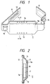
- An intake pipe 38 is provided for introducing fresh air to the air intake section 23 from an external space.
- An exhaust pipe 39 is connected to the exhaust section 27 for emitting the combustion gas to the external space.
- one end of the intake pipe 38 is connected to the intake section 23, and the other end of the intake pipe 38 is connected to an air filter 40 located in the belt portion 8.
- the exhaust pipe 39 can be arranged in the same manner as the intake pipe 38. According to this pipe arrangement, the ends of intake and exhaust passages (i.e., intake and exhaust ports) can be positioned far from each other.
- the fresh air is introduced from the external space via a gas permeable outer wall of the belt section 8, the air filter 40, the intake pipe 38 to the intake section 23.
- the control unit 4 comprises a time control section 41 for controlling a combustion time in the catalytic burning unit 2.
- the time control section 41 is equipped with a timer (not shown) for measuring an elapse of time during a supplying operation of the fuel gas from the fuel tank 1 to the catalytic burning unit 2. After the predetermined time has passed, the timer control section 41 of the control unit 4 closes the valve 19 to stop the fuel gas supplied to the catalytic burning unit 2.
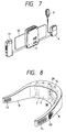
- a second embodiment provides a plurality of separate housing compartments 33a, 33b and 33c accommodating the fuel tank 1, the catalytic burning unit 2 and the control unit 4, respectively.
- the catalytic burning unit 2 is accurately positioned at a center when the belt portions 8 are wound around the operator's body and fixed by the connecting members 11. The rest of the arrangement is substantially the same as the components shown in the first embodiment.
- the fuel tank 1, the catalytic burning unit 2 and the control unit 4 need not be fixed to the inside wall of the housing 9 since they are accurately positioned in the separate compartments 33a, 33b and 33c without changing their mutual positional relationship.
- the second embodiment provides a comfortable warmer capable of warm an intended portion of the user's body accurately at a desired temperature.
- a third embodiment provides a plurality of lower ventilation holes 34 on a bottom of the housing 9 (although only one hole 34 is shown in Fig. 6).
- a plurality of upper ventilation holes 35 are provided on a top of the housing 9 (although only one hole 35 is shown in Fig. 6). More specifically, the upper ventilation holes 35 are opened on a lid 36 closing the housing 9. The rest of the arrangement is substantially the same as the components shown in the first embodiment.
- air can be smoothly introduced into the housing 9 via the lower ventilation holes 34 provided at the bottom of the housing 9 without causing any interference with user's clothes.
- the catalytic burning unit 2 accommodated in the housing 9 can receive a sufficient amount of fresh air for adequately maintaining the catalytic combustion.
- the exhaust gas can be smoothly emitted from the upper ventilation holes 35 provided at the top of the housing 9.
- a fourth embodiment provides a heat transfer board 37 formed by a thin metallic plate which is positioned in the housing 9 of the heater section 7.
- the heat transfer board 37 extends from the catalytic burning unit 2 toward each belt portion 8.
- the heat transfer board 37 is made of a heat conductive member, such as aluminum.
- the heat transfer board 37 may be a flexible member, such as a metallic fabric or a metallic net, that is easily bent along a curve of the user's body. The rest of the arrangement is substantially the same as the components shown in the first embodiment.
- the embodiment of the fourth embodiment it becomes possible to smoothly diffuse the heat generated from the catalytic burning unit 2 via the heat transfer board 37 to the heat radiation board 7a of heater section 7 and the belt portion 8.
- a wide area of the user's body can be warmed up via a curved heat transfer surface along the user's body.
- the heat of catalytic burning unit 2 can be effectively transmitted to the user's body.
- a catalytic burning type warmer comprises a catalytic heat generating apparatus, a heater section, and a pair of belt portions.
- the catalytic heat generating apparatus comprises a fuel tank for storing fuel gas, and a catalytic burning section connected to the fuel tank for generating heat based on an oxidative reaction between the fuel supplied from the fuel tank and air.
- the heater section comprises a housing for accommodating the catalytic heat generating apparatus.
- the belt portions are provided at both ends of the heater section for fixing the heater section to a user's body.
- the housing has an opening for taking the catalytic heat generating apparatus into and out of the housing.
- This arrangement makes it possible to take the catalytic burning section, the fuel tank and the control section out of the housing. Repair and adjustment of each component can be easily done.
- the beater section which may be subjected to sweat, can be washed and kept clean.
- the catalytic burning section is securely held in the housing by an appropriate fixing member. This arrangement makes it possible to prevent the catalytic burning section or the like from dislocating or fluctuating in the housing even when the user moves for walking or running, providing a stabilized heating performance.
- the catalytic heat generating apparatus comprises a plurality of separate units, and the fuel tank is connected to the catalytic burning section via a flexible connecting member. This provides a good weight balance in installing the heat generating components into the heater section. This gives a better feeling to the user when the warmer is used, without causing an undesirable leaning of the apparatus components.
- the heater section comprises a plurality of ventilation holes for communicating an inside space of the housing with an external space.
- external air can be smoothly introduced into the catalytic burning section.
- the exhaust gas produced by the combustion in the catalytic burning section can be smoothly emitted.
- Ventilation holes is provided on a bottom of the housing. This arrangement prevents the holes from being closed by a jacket or a coat when the user wears it on the warmer.
- the catalytic burning section comprises an intake section for introducing air from an external space and an exhaust section for emitting combustion gas.
- At least one passage is provided to connect either of the intake and exhaust sections to the external space.
- the passage has one end connected to either of the intake and exhaust sections and the other end extended to one of the belt portions and communicated with the external space.
- the heater section comprises a heat transfer board for diffusing the heat generated effectively from the catalytic burning section.
- a cushion member is provided on at least one of the heater section and the belt portions. It becomes possible to fit the warmer along the user's body with an adequate resilient force. A movement of the user can be absorbed, and a preferable feeling can be obtained when the warmer is used.
- the fuel tank is detachable from the catalytic heat generating apparatus, and a storage is provided on at least one of the belt sections for storing a spare fuel tank.
- a storage is provided on at least one of the belt sections for storing a spare fuel tank.
- a control section is provided for feedback controlling a temperature of the catalytic burning section to a set value.
- control section is associated with a handy controller for allowing a user to set a desirable temperature.
- the handy controller may be detachably held in a holder provided on one of the belt portions.
- a time control section is provided in the control section for controlling a combustion time in the catalytic burning section.
- the time control section stops the fuel gas supplied to the catalytic burning section in response to an elapse of a predetermined time after starting a supplying operation of the fuel gas from the fuel tank to the catalytic burning section.
- a fuel tank (1) stores fuel gas.
- a catalytic burning section (2) is connected to the fuel tank for generating heat based on an oxidative reaction between the fuel supplied from the fuel tank and air.
- the fuel tank (1) and the catalytic burning section (2) are assembled as a catalytic heat generating apparatus (32).
- the catalytic heat generating apparatus (32) is detachably installed in a housing (9) of a heater section (7).
- the heater section (7) has both ends provided with a pair of belt portions (8) wound around a user's body.
Landscapes
- Health & Medical Sciences (AREA)
- Emergency Medicine (AREA)
- Physics & Mathematics (AREA)
- Thermal Sciences (AREA)
- Engineering & Computer Science (AREA)
- Biomedical Technology (AREA)
- Heart & Thoracic Surgery (AREA)
- Vascular Medicine (AREA)
- Life Sciences & Earth Sciences (AREA)
- Animal Behavior & Ethology (AREA)
- General Health & Medical Sciences (AREA)
- Public Health (AREA)
- Veterinary Medicine (AREA)
- Thermotherapy And Cooling Therapy Devices (AREA)
- Gas Burners (AREA)
Applications Claiming Priority (9)
| Application Number | Priority Date | Filing Date | Title |
|---|---|---|---|
| JP7946897 | 1997-03-31 | ||
| JP9079468A JPH10274402A (ja) | 1997-03-31 | 1997-03-31 | 触媒燃焼加熱式採暖器 |
| JP79468/97 | 1997-03-31 | ||
| JP34112897A JP3329247B2 (ja) | 1997-12-11 | 1997-12-11 | 触媒燃焼式温熱用具 |
| JP34112897 | 1997-12-11 | ||
| JP341128/97 | 1997-12-11 | ||
| JP05172998A JP3911824B2 (ja) | 1998-03-04 | 1998-03-04 | 保温器 |
| JP51729/98 | 1998-03-04 | ||
| JP5172998 | 1998-03-04 |
Publications (3)
| Publication Number | Publication Date |
|---|---|
| EP0868893A2 true EP0868893A2 (de) | 1998-10-07 |
| EP0868893A3 EP0868893A3 (de) | 2000-01-19 |
| EP0868893B1 EP0868893B1 (de) | 2005-06-01 |
Family
ID=27294416
Family Applications (1)
| Application Number | Title | Priority Date | Filing Date |
|---|---|---|---|
| EP98105742A Expired - Lifetime EP0868893B1 (de) | 1997-03-31 | 1998-03-30 | Tragbare Wärmvorrichtung geeignet für einen Körper |
Country Status (3)
| Country | Link |
|---|---|
| US (1) | US6206909B1 (de) |
| EP (1) | EP0868893B1 (de) |
| DE (1) | DE69830354T2 (de) |
Cited By (1)
| Publication number | Priority date | Publication date | Assignee | Title |
|---|---|---|---|---|
| CN109223510A (zh) * | 2018-10-22 | 2019-01-18 | 赵磊 | 一种多功能中医疼痛科腿部熏蒸理疗装置 |
Families Citing this family (18)
| Publication number | Priority date | Publication date | Assignee | Title |
|---|---|---|---|---|
| US6425913B1 (en) * | 2000-06-01 | 2002-07-30 | Richard C. C. Chao | Electrical heating correcting waist pad |
| EP1442254B1 (de) * | 2001-10-09 | 2013-11-06 | Global Heating Technologies GmbH | Katalytische membran-heizvorrichtung |
| JP5046869B2 (ja) * | 2007-11-07 | 2012-10-10 | 三洋電機株式会社 | コードレスアンカ |
| US9962284B2 (en) * | 2007-12-19 | 2018-05-08 | Johnson & Johnson Consumer Inc. | Thermal treatment device |
| JP2011512902A (ja) * | 2008-02-25 | 2011-04-28 | マクニール−ピーピーシー・インコーポレーテツド | 熱治療装置 |
| US20100161014A1 (en) * | 2008-12-23 | 2010-06-24 | Lynch Joseph M | Thermal treatment device |
| US20100210984A1 (en) * | 2009-02-19 | 2010-08-19 | Chien-Chou Chen | Electro-thermal protecting device for heat treatment |
| EP4119095A1 (de) | 2011-03-21 | 2023-01-18 | Cephea Valve Technologies, Inc. | Scheibenförmige ventilvorrichtung |
| TWI494097B (zh) * | 2013-07-02 | 2015-08-01 | 可伸縮調整之加熱護具 | |
| US8870948B1 (en) | 2013-07-17 | 2014-10-28 | Cephea Valve Technologies, Inc. | System and method for cardiac valve repair and replacement |
| EP4306080A3 (de) | 2014-12-09 | 2024-04-10 | Cephea Valve Technologies, Inc. | Ersatzherzklappen und herstellungsverfahren |
| US10849746B2 (en) | 2015-05-14 | 2020-12-01 | Cephea Valve Technologies, Inc. | Cardiac valve delivery devices and systems |
| EP4335415A3 (de) | 2015-05-14 | 2024-05-29 | Cephea Valve Technologies, Inc. | Ersatzmitralklappen |
| CN105726195B (zh) * | 2016-03-18 | 2018-10-12 | 泰州梅兰日用品有限公司 | 肩用暖宝宝 |
| EP3471665B1 (de) | 2016-06-17 | 2023-10-11 | Cephea Valve Technologies, Inc. | Vorrichtungen zur herzklappenfreisetzung |
| EP4209196A1 (de) | 2017-01-23 | 2023-07-12 | Cephea Valve Technologies, Inc. | Ersatzmitralklappen |
| EP3570779B1 (de) | 2017-01-23 | 2023-02-15 | Cephea Valve Technologies, Inc. | Ersatzmitralklappen |
| CN111568641B (zh) * | 2020-05-28 | 2021-04-23 | 刘子琛 | 一种眼罩发热材料及制备工艺 |
Citations (3)
| Publication number | Priority date | Publication date | Assignee | Title |
|---|---|---|---|---|
| JPS4860708U (de) | 1971-11-12 | 1973-08-02 | ||
| JPS49108290U (de) | 1972-12-30 | 1974-09-17 | ||
| JPS508039U (de) | 1973-05-25 | 1975-01-28 |
Family Cites Families (13)
| Publication number | Priority date | Publication date | Assignee | Title |
|---|---|---|---|---|
| US912527A (en) * | 1906-04-26 | 1909-02-16 | Frank Batter | Portable foot and body warmer. |
| JPS5039091B2 (de) | 1971-12-03 | 1975-12-15 | ||
| JPS5439898B2 (de) | 1973-05-25 | 1979-11-30 | ||
| JPS49108290A (de) | 1973-12-18 | 1974-10-15 | ||
| US4180922A (en) * | 1978-02-07 | 1980-01-01 | Cieslak Leonard K | Boot warmer |
| US4281418A (en) * | 1978-02-07 | 1981-08-04 | Stanley Cieslak | Portable furnace for wearing apparel |
| DE2851602A1 (de) * | 1978-11-29 | 1980-06-12 | Messerschmitt Boelkow Blohm | Geraet zur behandlung entzuendlicher erkrankungen |
| EP0014300A1 (de) * | 1979-02-05 | 1980-08-20 | Wath AG | Unabhängiges Wärmegerät, insbesondere für die Therapie der neuroartikularen Pathologie |
| US4676247A (en) * | 1985-08-21 | 1987-06-30 | Cleve Ardry J Van | Multi-pocket therapeutic anatomical wrap |
| US4685442A (en) * | 1987-01-20 | 1987-08-11 | Leonard Cieslak | Portable heater for wearing apparel |
| FR2708196A1 (fr) * | 1993-07-28 | 1995-02-03 | Applic Gaz Sa | Ceinture autonome de chauffage. |
| US5928275A (en) * | 1995-11-06 | 1999-07-27 | Yates; James W. | Body warmer belt |
| US5665057A (en) * | 1996-03-20 | 1997-09-09 | Murphy; Michael G. | Heated back supporting device |
-
1998
- 1998-03-30 EP EP98105742A patent/EP0868893B1/de not_active Expired - Lifetime
- 1998-03-30 DE DE69830354T patent/DE69830354T2/de not_active Expired - Fee Related
- 1998-03-31 US US09/052,007 patent/US6206909B1/en not_active Expired - Fee Related
Patent Citations (3)
| Publication number | Priority date | Publication date | Assignee | Title |
|---|---|---|---|---|
| JPS4860708U (de) | 1971-11-12 | 1973-08-02 | ||
| JPS49108290U (de) | 1972-12-30 | 1974-09-17 | ||
| JPS508039U (de) | 1973-05-25 | 1975-01-28 |
Cited By (1)
| Publication number | Priority date | Publication date | Assignee | Title |
|---|---|---|---|---|
| CN109223510A (zh) * | 2018-10-22 | 2019-01-18 | 赵磊 | 一种多功能中医疼痛科腿部熏蒸理疗装置 |
Also Published As
| Publication number | Publication date |
|---|---|
| EP0868893A3 (de) | 2000-01-19 |
| US6206909B1 (en) | 2001-03-27 |
| DE69830354T2 (de) | 2006-01-26 |
| EP0868893B1 (de) | 2005-06-01 |
| DE69830354D1 (de) | 2005-07-07 |
Similar Documents
| Publication | Publication Date | Title |
|---|---|---|
| US6206909B1 (en) | Portable warmer suitable for a body | |
| US6098612A (en) | Heating garment | |
| EP0948908B1 (de) | Heizjacke | |
| US5799640A (en) | Fuel feed device for gas engines and gas-engine-powered working machine | |
| GB2107980A (en) | Hair drying apparatus | |
| US4095938A (en) | Arctic vehicle battery heater | |
| CA2208973C (en) | Heating garment | |
| JP3329247B2 (ja) | 触媒燃焼式温熱用具 | |
| US3785362A (en) | Radiating system for body warming devices | |
| US5947109A (en) | Delivery warmer | |
| KR200208669Y1 (ko) | 의류 또는 매트류의 휴대용 난방 공급장치 | |
| JPH09126426A (ja) | 燃焼装置 | |
| JP2001104125A (ja) | 暖房寝具 | |
| JPH10183412A (ja) | 暖房衣類 | |
| JP2000005212A (ja) | 保温器 | |
| KR20020005347A (ko) | 의류 또는 매트류의 휴대용 난방 공급장치 | |
| JP4075188B2 (ja) | 暖房装置 | |
| JP3911824B2 (ja) | 保温器 | |
| JP2000014692A (ja) | 保温器 | |
| JPH11253478A (ja) | 保温器 | |
| JP2000300469A (ja) | 暖房装置 | |
| JPH11318667A (ja) | 暖房寝具 | |
| JP3982058B2 (ja) | 熱搬送装置 | |
| US4852546A (en) | Hair roller heating device | |
| JPS609607Y2 (ja) | 簡易コンロ |
Legal Events
| Date | Code | Title | Description |
|---|---|---|---|
| PUAI | Public reference made under article 153(3) epc to a published international application that has entered the european phase |
Free format text: ORIGINAL CODE: 0009012 |
|
| 17P | Request for examination filed |
Effective date: 19980330 |
|
| AK | Designated contracting states |
Kind code of ref document: A2 Designated state(s): DE FR IT NL |
|
| PUAL | Search report despatched |
Free format text: ORIGINAL CODE: 0009013 |
|
| AK | Designated contracting states |
Kind code of ref document: A3 Designated state(s): AT BE CH DE DK ES FI FR GB GR IE IT LI LU MC NL PT SE |
|
| AX | Request for extension of the european patent |
Free format text: AL;LT;LV;MK;RO;SI |
|
| AKX | Designation fees paid |
Free format text: DE FR IT NL |
|
| 17Q | First examination report despatched |
Effective date: 20020814 |
|
| GRAP | Despatch of communication of intention to grant a patent |
Free format text: ORIGINAL CODE: EPIDOSNIGR1 |
|
| GRAS | Grant fee paid |
Free format text: ORIGINAL CODE: EPIDOSNIGR3 |
|
| GRAA | (expected) grant |
Free format text: ORIGINAL CODE: 0009210 |
|
| AK | Designated contracting states |
Kind code of ref document: B1 Designated state(s): DE FR IT NL |
|
| PG25 | Lapsed in a contracting state [announced via postgrant information from national office to epo] |
Ref country code: NL Free format text: LAPSE BECAUSE OF FAILURE TO SUBMIT A TRANSLATION OF THE DESCRIPTION OR TO PAY THE FEE WITHIN THE PRESCRIBED TIME-LIMIT Effective date: 20050601 Ref country code: IT Free format text: LAPSE BECAUSE OF FAILURE TO SUBMIT A TRANSLATION OF THE DESCRIPTION OR TO PAY THE FEE WITHIN THE PRESCRIBED TIME-LIMIT;WARNING: LAPSES OF ITALIAN PATENTS WITH EFFECTIVE DATE BEFORE 2007 MAY HAVE OCCURRED AT ANY TIME BEFORE 2007. THE CORRECT EFFECTIVE DATE MAY BE DIFFERENT FROM THE ONE RECORDED. Effective date: 20050601 |
|
| REF | Corresponds to: |
Ref document number: 69830354 Country of ref document: DE Date of ref document: 20050707 Kind code of ref document: P |
|
| NLV1 | Nl: lapsed or annulled due to failure to fulfill the requirements of art. 29p and 29m of the patents act | ||
| PLBE | No opposition filed within time limit |
Free format text: ORIGINAL CODE: 0009261 |
|
| STAA | Information on the status of an ep patent application or granted ep patent |
Free format text: STATUS: NO OPPOSITION FILED WITHIN TIME LIMIT |
|
| 26N | No opposition filed |
Effective date: 20060302 |
|
| EN | Fr: translation not filed | ||
| PG25 | Lapsed in a contracting state [announced via postgrant information from national office to epo] |
Ref country code: FR Free format text: LAPSE BECAUSE OF FAILURE TO SUBMIT A TRANSLATION OF THE DESCRIPTION OR TO PAY THE FEE WITHIN THE PRESCRIBED TIME-LIMIT Effective date: 20050601 |
|
| PGFP | Annual fee paid to national office [announced via postgrant information from national office to epo] |
Ref country code: DE Payment date: 20090327 Year of fee payment: 12 |
|
| PG25 | Lapsed in a contracting state [announced via postgrant information from national office to epo] |
Ref country code: DE Free format text: LAPSE BECAUSE OF NON-PAYMENT OF DUE FEES Effective date: 20101001 |